
Chapter 7
Networking and Remote Access
Abstract
This chapter describes networking in some detail, with special attention to remote simulation and access. Remote simulation has high and frequent use in high-performance computing (HPC) and it is the beauty of HPC that you can access your work from anywhere in the world. The concept of networking with transmission control protocol/Internet protocol is also discussed and presented in a simplified manner that should help a computational flow dynamics engineer to work well when dealing with cluster issues.
Keywords
HPC; Networking; Remote simulation; TCP/IP1. Transmission Control Protocol/Internet Protocol
When you send a letter to your friend living abroad, you write more than his name in the “send to” part: You also write his complete address. In the address you say more than just the city name, like London or Manchester, you write the town name, the street address, and the house number. In the same way, when you access the network, your domain name server Internet protocol (IP) is a particular address that you specify in the Internet explorer. This particular address, which you usually do not see, is the IP. It is a unique number consisting of a set of four three-digit numbers separated by a dot. What you usually see is the Web address, such as http://www.google.com or http://www.yahoo.co.uk. Before we proceed further, it seems worth mentioning that this portion could be boring to a computational flow dynamics (CFD) user, because many things are related to information technology or computer sciences, but they are equally linked to CFD jobs because networking is the backbone of high-performance computing (HPC).
With this understanding of the importance of an IP address, we will go into further into its details. There must be some standard way to address the IP; otherwise, data can be lost as in the case of mail delivery when you give no address or an ambiguous one. Standardization is done by the Internet Assigned Numbers Authority, which assign IPs to the international domain and to organizations. Small organizations or individual users can obtain an IP from Internet service providers.
Internet protocol addressing is done by assigning a 32-bit address code, which is a set of four three-digit numbers. The address in binary number format may look like:
11000011 00100010 00001100 00000111
which in decimal format can be written as:
195.34.12.7
This is much easier to remember than the binary format. The type of number formatting is further divided into two parts: the network and the host node on the station of the network.
1.1. Internet Protocol Classes
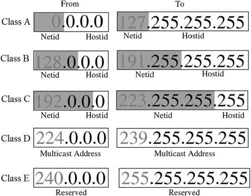
Based on this division into two parts, IP addresses involve different types of classes. There are five standard classes of IP addresses. They are constructed using different combinations of node and host, as shown in Figure 7.1. The classes are categorized as A, B, C, D, and E. Figure 7.2 explains this in detail for each class:
• Class A Class A addresses use an 8-bit network number and a 24-bit node number. Therefore, Class A addresses can have up to 224 − 2 = 16,777,214 hosts on a single network. Class A addresses are in the range: 10.0.0.0 to 127.255.255.255.
• Class B Class B addresses use a 16-bit network number and a 16-bit node number. Thus Class B addresses can have up to 216 − 2 = 65,534 hosts on a network. Class B addresses are in the range (beginning with 128 because 127 belongs to Class A addresses): 128.1.0.0 to 191.255.255.255.
• Class C Class C addresses use a 24-bit network number and an 8-bit node number. Class C addresses can have up to 28 − 2 = 254 hosts on a network. Class C addresses are in the range (beginning with 192): 192.0.0.0 to 223.255.255.255.
• Class D Class D addresses are used for multi-casts (messages sent to many hosts). Class D addresses are in the range: 224.0.0.0 to 239.255.255.255.
• Class E These addresses are for experimental use.
The address with all zeros in the host address (for example, in class C, 192.168.0.0 (11000000.10101000.00000000.00000000)) is the network address and cannot be assigned to any machine. The address with all ones in the host address (11000000.10101000.00000000.11111111 = 192.168.0.255) is the network broadcast address. This addressing structure allows IP addresses to uniquely identify each physical network and each node on each physical network. For a particular value of the address, the base address of the host with all zeros is known as the network address and not allotted to the host. Similarly, the top address of the range host address of all ones is not assigned because it is used for broadcasting data to all hosts with the same network address.

1.2. Special IP Addresses
Some special types of IP addresses are unique and are used for a particular type of work:
• Network address: All of the host identifications (IDs) in this type of address contain all zeros (in binary notation).
• Direct broadcast address: In this address, all of the host IDs contain all ones. The direct broadcast address is used by the router to send a message to every host on a local network. Every host/router then receives and processes the data with direct broadband address.
• Limited broadcast address: The net ID and host ID contain all ones (in binary notation). A limited broadcast address is used by a host to send a packet to every host on the same network. The data packets are blocked by the router to confine the packets to the local network.
• Loop back address: This kind of address begins with 127, so it is always of the type 127.x.y.z. In FLUENT, when accessing multiple personal computers (PCs), it identifies the nodes on the basis of their IPs. This creates problems if the file/etc./hosts contain a loop back address at the end that is not commented by default. To run FLUENT that this line must be commented.
1.3. Subnetting
Consider a network with millions of hosts. For example, class A contains over 16 million host IDs, which is not practical. This also causes broadcast problem and IP addresses are not used efficiently in this way. A remedy for this is to make groups in the host IDs so that they are used effectively. It also reduces network traffic and makes it simple to manage, and contains smaller broadcast domains. Subnetting an IP network is done for a variety of reasons, including using different physical media (such as Ethernet, FDDI, and WAN), preserving address space, and reasons of security. The most common reason is to control network traffic. In an Ethernet network, all nodes on a segment see of all the packets transmitted by all other nodes on that segment. Performance can be adversely affected under heavy traffic loads, owing to collisions and resulting retransmissions. A router is used to connect IP networks to minimize the amount of traffic each segment must receive. In subnetting, large networks need to be divided into smaller networks. These smaller divisions are called subnetworks and provide addressing flexibility. Most of the time subnetworks are simply referred to as subnets. A primary reason for using subnets is to reduce the size of a broadcast domain. When broadcast traffic begins to consume too much of the available bandwidth, network administrators may choose to reduce the size of the broadcast domain.
Similar to the host number portion of class A, B, and C addresses, subnet addresses are assigned locally, usually by the network administrator. Like other IP addresses, each subnet address is unique (Figure 7.3).
Thus, the subnet number simply gets some bits from host and helps the network to use them. It determines which part of an IP address is the network field and which is the host field. It can be 32 bits long and has 4 octets, just like an IP address.

1.4. Subnet Masking and Example
Applying a subnet mask to an IP address allows you to identify the network and node parts of the address. The network bits are represented by the ones in the mask and the host bits are represented by the zeros. Performing a bit-wise logical AND operation between the IP address and the subnet mask results in the network address or number. A class B address can be effectively translated. For example, the IP address of 172.16.0.0 is assigned, but host addresses are limited to 255 maximum, allowing eight extra bits to use as a subnet address. The IP address of 172.16.97.235 would be interpreted as IP network address 172.16, subnet number 97, and node number 235. In addition to extending the number of addresses available, subnet addressing provides other benefits. It allows a network administrator to construct an address scheme for the network by using different subnets for other remote locations in the network or for other departments in an organization. The previous example uses the entire third octet for a subnet address, but this is not a restriction. To create more network numbers, just shift some bits from the host address to the network address. For instance, to partition a class C network number 192.68.135.0 (apologies if someone has same IP address) into two, you shift 1 bit from the host address to the network address. The steps are as follows:
1. Write down the network number in binary form, such as 192.68.135.0
(11000000.01000100.10000111.00000000).
2. Write down the net mask as 255.255.255.128
(11111111.11111111.11111111.10000000) (128 is just an example).
3. Now add these binary with logical and i.e., 1 + 1 = 1 and 1 + 0 = 0,
(11000000·01000100·10000111·10000000) = 192.68.135.128.
4. The subnet has network number 192.68.135.0 with hosts
192.68.135.1 to 129.68.135.126
5. The address 192.68.135.127 is not assigned because it is the broadcast address of the subnet.
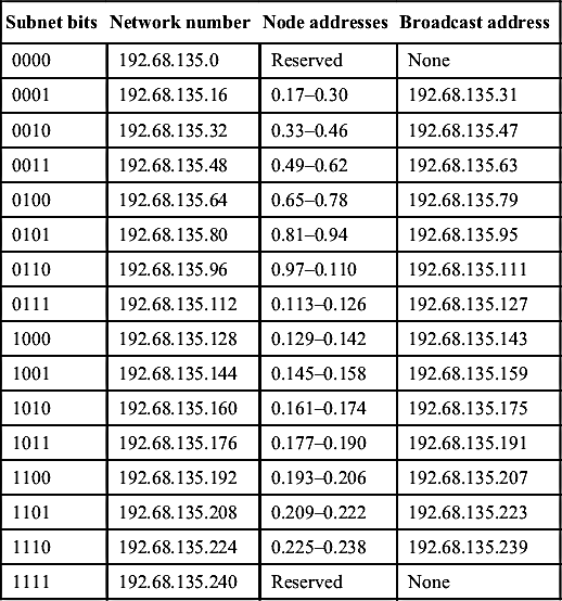
Similarly, if the subnet mask contains the last digit as 240, it would mean that the binary notation would be 11110000. In this way, the network can be split into 14 subnets of 14 nodes each. This will limit the network to 196 nodes instead of the 254 it would have had without subnetting, but it has the advantages of traffic isolation and security. To accomplish this, a subnet mask 4 bits long would be used. Table 7.1 explains this.
Table 7.1
Subnetting with 14 possible combinations
| Subnet bits | Network number | Node addresses | Broadcast address |
| 0000 | 192.68.135.0 | Reserved | None |
| 0001 | 192.68.135.16 | 0.17–0.30 | 192.68.135.31 |
| 0010 | 192.68.135.32 | 0.33–0.46 | 192.68.135.47 |
| 0011 | 192.68.135.48 | 0.49–0.62 | 192.68.135.63 |
| 0100 | 192.68.135.64 | 0.65–0.78 | 192.68.135.79 |
| 0101 | 192.68.135.80 | 0.81–0.94 | 192.68.135.95 |
| 0110 | 192.68.135.96 | 0.97–0.110 | 192.68.135.111 |
| 0111 | 192.68.135.112 | 0.113–0.126 | 192.68.135.127 |
| 1000 | 192.68.135.128 | 0.129–0.142 | 192.68.135.143 |
| 1001 | 192.68.135.144 | 0.145–0.158 | 192.68.135.159 |
| 1010 | 192.68.135.160 | 0.161–0.174 | 192.68.135.175 |
| 1011 | 192.68.135.176 | 0.177–0.190 | 192.68.135.191 |
| 1100 | 192.68.135.192 | 0.193–0.206 | 192.68.135.207 |
| 1101 | 192.68.135.208 | 0.209–0.222 | 192.68.135.223 |
| 1110 | 192.68.135.224 | 0.225–0.238 | 192.68.135.239 |
| 1111 | 192.68.135.240 | Reserved | None |
2. Secure SHell
With many Internet protocols such as Telnet, File Transfer Protocol (FTP), and Remote SHell (RSH), a problem was that while accessing the remote servers, the passwords were also transmitted in plain text, which was highly insecure. Common use of .rhost is an example. Thus, while connecting to the outside world domain through the Internet, a secure system of logging on was devised. Secure SHell (SSH) was produced for this purpose. It was developed by SSH Communications Security, Ltd and has both Linux- and Windows-based versions available. In Red Hat Linux, however, you do not need it.
Install SSH explicitly because the package offers installation. Some repositories for additional functionality may be obtained from the Internet. Secure SHell encodes all communications between two end points, eliminating the chance that passwords or other sensitive bits of information are discovered by intermediate sniffers (hackers). Secure SHell uses a public-key authentication-based system that is required for login into the remote server after you provide the password. For this purpose, RSH is now obsolete because as an authentication model it was insecure in a cluster environment. Secure Copy (SCP) is also part of safe and sound file copying between the two nodes of a cluster. OpenSSH is becoming popular for Linux-based systems because it is well-supported, easy to install, and portable.
2.1. Setting Name Resolution
Sometimes when you try to access remote nodes using their names, it displays a message about temporary failure in name resolution. This is because that the SSH does not know to which IP the remote node belongs. This can be easily solved by mentioning host names in the /etc/hosts file. If you do not yet have access to nodes through SSH, it would contain only one IP address, 127.0.0.1 which is a loop back and should be commented. In ANSYS FLUENT it does not access remote nodes because it searches for the loop back address. Thus, first mention the IP of the host PC (which you are currently on) and then its name, and then the domain name.
Similarly, in the second line mention the PC which you want to access, and then mention its IP, its name, and then the domain name. Now you are ready to log in through SSH. It is better to log out the terminal or open up a new terminal for SSH remote nodes.
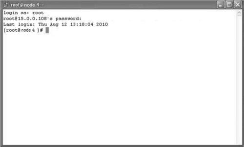
If you are on node01, type “ssh node02” where node02 is the name of the remote node you want to access. The first time, it will generate fingerprints and then ask to connect (yes or no?). Type “yes” and then it will ask for password. Type the password and it will log into the remote machine. To exit the node, type “exit.”
2.2. Setting a Password-Less Environment
While accessing the remote node, SSH asks for fingerprints only for the first time, as shown below, and stores the information into the /root/.ssh/ folder.
[root@node1] ssh-keygen -t rsa.
Generating public/private rsa key pair.
Enter file in which to save the key (/root/.ssh/id rsa):
Enter passphrase (empty for no passphrase):
Enter same passphrase again:
Your identification has been saved in/root/.ssh/id rsa.
Your public key has been saved in/root/.ssh/id rsa.pub.
The key fingerprint is:
f6:82:g8:27:35:cf:4c:6d:13:22:30:cf:5c:c8:a0:23
After this, whenever you log into the other node it will ask only for a password. Now, if we talk about ANSYS FLUENT parallel in an SSH environment, there must be no such thing as a password because Fluent cannot provide one. It would only pick up the local processors of the host PC. Thus, a password-less environment is mandatory.
For SSH, one must remember the two important file names “authorized keys” and “id rsa.pub”. They both are in the /root/.ssh/ folder. “id rsa.pub” contains the public key of the current PC you are logged into. The file “authorized keys” contains the list of the public keys of all of the remote PCs to which you want to connect and the host PC itself. Initially in the .SSH directory you will have No file in it. Probably one file would exist if you logged in multiple times to your PC or remote PC. You do not need to worry about that. However, from anywhere (apart from root) you can start generating the files in the .SSH folder. To generate the files, type the following (assuming this computer name is node1):
[root@node1] ssh-keygen -t rsa.
This will create the id_rsa and id_rsa.pub in the folder /root/.ssh. id_rsa will contain the private key while id_rsa.pub will contain the public key. You need to copy this to your own authorized keys file as well as to the authorized keys file of other PCs. To avoid error from manual copying, type the following command:
[root@node1] cat/root/.ssh/id rsa.pub | ssh root@node2 'cat >>/root/.ssh/authorized keys'
Note: the above statement must be typed in one line on the terminal; because of brevity, the page in this chapter was typed on two lines.
This will copy the keys into the authorized keys of node1 into the authorized keys file of node2.
2.3. Remote Access on a Linux Platform
Networking acts as a backbone in clustering. Not having networking is the same as constructing a building without pillars. The network allows the nodes to communicate and exchange data. An excellent network is one that has low latency and high bandwidth.
Common networks in use today are Gigabit and Infiniband. They differ mainly with respect to the speed they provide. When you are ready to submit your job there is one more intermediate task.
Clusters work in a batch environment. The basic idea is that you create a task and make a script to submit the task or job. This job is submitted via a job scheduler. As you submit a job, if everything goes fine your job will start running. It may also wait in a queue, but that is not an issue because it may not have enough resources to run at the time you submit the job. Be patient. Within the script you tell the cluster many things, normally including your job name, the number of cores, the number of nodes, your e-mail address, the time to wait in a queue, the time to running the job, etc. A typical script for ANSYS FLUENT is mentioned below with PBS job scheduler.
#PBS -N name
#PBS -l walltime=10:00:00
#PBS -l nodes=2:ppn=2
#PBS -j oe
# Run FLUENT
fluent 2ddp -t4 -cnf=$PBS NODEFILE -g –i input.txt > logfile.$$
2.3.1. PuTTY
Most of the cluster environments are Linux-based, so one way to access the cluster via your remote desktop Windows-based PC is through PuTTY. PuTTY is an SSH client for remote access. This requires the IP of the cluster control node and its username and password (Figure 7.4). After you log into the PC for the first time, it asks to store the information you provided into the cache, similar to the login procedure when you do it for the first time for SSH (Figure 7.5). Then you enter the username and password and log in. You will see a Linux terminal opened (usually black).
Now you are ready to submit your job if your script is ready. To submit the job, a job scheduler is necessary. Even if you do not have a job scheduler, you can successfully run your tasks of ANSYS FLUENT; when you do not have a time limitation and not many users to work on a cluster, so you can easily work without a job scheduler. There are three options for running your task: (1) without a job scheduler or graphics; (2) without a job scheduler and with graphics; and (3) with a job scheduler.
2.3.1.1. Without a Job Scheduler or Graphics
If you want to run your job of Fluent without a job scheduler, it is useful to set up your case and data files on your own PC before running it onto the cluster. Then, transfer the files onto the cluster account via WinSCP and after that open up the PuTTy terminal and log in through your username and password. Then launch the ANSYS FLUENT via the command as follows:
fluent 3ddp -t16 -ssh -g -i <input> output 2&>1.
This will run a 3D double-precision (dp) version of Fluent using 16 cores (t16) without graphics (-g) and through ssh (-ssh) using the input file (input.txt)and two& runs the process in background. After Fluent launches, you will see something strange: If you have all of the FLUENT licenses available, it will pick the 16 cores of only your current node. No other machines in the list of the machines will be shown by FLUENT. Why is it so? It is because you have not told ANSYS FLUENT to pick up the machine file containing machine names.

For this purpose, type the following:
fluent 3ddp -t16 -ssh -g -i -cnf=host <input> output 2&>1.
where the host file contains the name of machines to be used. The correct path must be given if the file is somewhere other than the FLUENT directory. The following must be taken into account while writing the host file. Type the host name first. If the machine is multi-core and you have all the licenses available, write the machine name as many times as the number of cores. Thus, for a quad-core machine you will type the machine name four times. After entering all of the machine names, leave one extra line by pressing Enter and then save and quit your file. Do all of this in the PuTTy or Linux terminal through the vi editor. Caution: Do not edit any text document like that in Windows because the format will change and Linux will not recognize it. The input file will contain the commands to be executed by Fluent after running the above command. This is not Linux-specific; rather, it is FLUENT specific. A sample is shown below:
rc mytask.cas.
rd mytask.dat.
it 1000 wc mytask-1000.cas.
wd mytask-1000.dat.
exit
This will read case and data files, iterate for 1000 iterations, and, if everything goes fine, write case and data files. A number of commands for different tasks in Fluent can be found in the Fluent Text Command List. You may also write your output to an output file that will show the output of all of your iterations as you Fluent-finish the calculations.
2.3.1.2. Without Job Scheduler and with Graphics
The method is not different from the one described above. An exception is that a third piece of software, Xming, is used for graphics options. You need to install Xming on your local Windows PC. While in the PuTTy console you will put check the SSH tab to enable the X11 forwarding option. When you will launch PuTTy and you type a command such as gedit on the terminal, it will open the gedit window. This will not work if Xming is not installed and you have not enabled X11 forwarding.
Similarly, when you type “Fluent,” Fluent will run in graphics mode with its GUI. If you have a low-bandwidth connection between your PC and the remote cluster, it could be a bottleneck because the graphics will take a lot of time to load and it will take many seconds to respond after you click. When launching Fluent, you type the same command as mentioned above and drop the -g switch. If you are far behind the cluster in another city or country, you will run your work through the Internet. You will log in using ssh –X <username>@<domain name> and the -X will enable the graphics option in Linux mode.
2.3.1.3. With Job Scheduler
In the job scheduler you do not see the graphics. You can do so by saving the outputs momentarily so that you can view them using another PuTTy console. The job scheduler helps you manage your work and sets your job in a queuing system. If some nodes are free as you requested, your job will start immediately. The job submission command is qsub <scriptname>. To check the status of the job, type “qstat.” A typical script for the job submission of a Fluent task is given below:
#PBS -N name.
#PBS -l walltime=10:00:00
#PBS -l nodes=2:ppn=2
#PBS -j oe
# Run FLUENT
fluent 2ddp -t4 -cnf=$PBS NODEFILE -g –i input.txt > output.$$
The first line should contain the job name. The second line specifies the running time of the job. The third line specifies the number of nodes followed by the term “ppn,” which means processor (cores) per node. This can be used intelligently: for example, you have five nodes and you want to run your job on 24 cores, so you should not run you job on five nodes, but rather use three nodes and run with eight cores per node (assuming eight cores per node). The last line specifies the job output name. All of the lines with a hash symbol followed by “PBS” are job scheduler commands; the rest are comments. The last line of the job scheduler contains the command for FLUENT execution.
The explanation given above is for accessing the local area network via a single domain. However, in practice it is different. When you are sitting miles from your cluster, you normally gain access through the Internet. From PuTTy you first log into a login node and then from the login node you access the nodes as described above. If you gain access through the Internet, first type the username and password of the login node. Then type:
ssh -X username@<; IP address>
where the username would be your username and the IP address would be the IP of the login node network or the domain name server. Then you can SSH your other nodes in the usual manner. The –X switch enables the graphics option in accessing SSH. Consequently, writing –x instead of –X would disable it.
3. WinSCP
WinSCP stands for Windows Secure Copy, a free and open-source SFTP and FTP client for Microsoft Windows. Its main function is secure file transfer between a local and a remote computer. Beyond this, WinSCP offers basic file manager and file synchronization functionality. For secure transfers, it uses Secure Shell (SSH) and supports the SCP protocol. When you want to transfer data from your user node on Windows to the control node, you transfer files through this software. This has a much more user-friendly layout than PuTTY. WinSCP contains two panels: the left is the user computer (which is Windows-based) and the right is a Linux-based control node, as shown in Figure 7.6.
4. Running ANSYS FLUENT in an WinHPC Environment
Microsoft introduced Windows HPC Server 2008 to run HPC applications in a user-friendly environment. Because Linux is dry and requires memorizing a lot of commands, WinHPC lets the user do all of it in a GUI environment. However, in my opinion (most readers might disagree with me) Windows cannot compete with Linux. Ninety percent of the clusters in the world run on Linux. However, Tianhe-1A has the provision of performing calculations using WinHPC 2008. This is because Windows has certain issues that do not exist with Linux. This is a separate discussion; the main focus here is to explain how to run ANSYS FLUENT in an WinHPC environment. Images of ANSYS FLUENT menus are given for a clear understanding of the process.

4.1. ANSYS FLUENT Installation with a WinHPC Platform
1. Install and configure ANSYS FLUENT network parallel HPC
Before installing FLUENT, we assume that Microsoft HPC is installed and configured properly and that the compute nodes can access the head node. The Windows HPC Server 2008 Guide can be accessed to solve WinHPC issues, at http://technet.microsoft.com/en-us/library/cc793950.aspx. This guide is also available with the installation files for Microsoft HPC Pack 2008 (HPC GettingStarted.rtf, in the root folder).
2. Install ANSYS FLUENT (it is only necessary to install FLUENT on the head node).
The new directory structure will install FLUENT in:
C:Program FilesANSYS Incv1xxfluent.
3. Share the Fluent directory that sits under C:Program FilesANSYS Incv1xx, where xx is your ANSYS version number, so that all computers on the cluster can access this shared directory through the network (Figure 7.7).

4. Setup your ANSYS FLUENT working directory as a shared network drive. (A working directory is the directory where your case and data files reside.)
5. Go to Start Menu, Computer, and select Map Network Drive from the menu near the top of the screen (Figure 7.8).
6. Select a Drive letter and then press Browse … to your working directory: for example, C:Working (Figure 7.9).
7. Configure HPC clients
A client machine is any machine on the network that can access the cluster through the network. The following requirements are prerequisite.
a. Client machines must run Microsoft Windows XP 64-bit, Windows Vista 64-bit, Windows 7 64-bit, or Microsoft 2008 Server 64-bit.
b. If you only have 32-bit clients, you can run FLUENT on the HPC cluster but you must run in batch mode using a journal file.
c. Client machines must have a high-end video card with the latest graphics driver preinstalled by the vendor.


8. Remote Desktop Connection support
Many times, launching ANSYS FLUENT using Remote Desktop Connection will not result in display issues if the HPC cluster head node has a PCI Express ×16 Graphics card installed with the latest graphics driver and if the client machines are using the latest Remote Desktop Client (version 6). If these conditions are not met, you must launch FLUENT from a 64-bit client machine after installing Microsoft HPC Pack.
9. ANSYS FLUENT startup command
If you are running via Remote Desktop Connection, the default driver FLUENT will use is Microsoft Windows. If you run into graphics issues, check which driver ANSYS FLUENT is using.
• Open up FLUENT
• Choose Help menu, Version

• Try using the OpenGL driver by starting FLUENT with the following flag: fluent -fluent options ‘‘-driver opengl” as shown in Figure 7.10.
• Check Graphics Version once FLUENT is launched, to verify that it is using the OpenGL driver.
10. Configuring HPC client machines to access the cluster
a. Install HPC Pack 2008 on client machines from the head node network share called C:Program FilesMicrosoft HPC PackData
eminst or from the CD.
b. Open up the reminst directory and double-click on the setup.exe file. Some additional programs may be required: for example, .NET Framework. The installer will prompt you to install these programs.
11. Options with FLUENT
a. It is easiest to make a shortcut to the fluent.exe file from the head node onto the client machines. The fluent.exe is usually located in C:Program FilesANSYS Incv1xxfluent
tbinwin64.
b. Launch FLUENT from the shortcut on your desktop.
c. Choose your Dimension, Display Options. Under Options, choose Double Precision if necessary. Choose Use Microsoft Job Scheduler. You can also request resources but delay the launching of ANSYS FLUENT until the actual resources are allocated. In the ANSYS FLUENT GUI, choose the Scheduler tab then check “Start When Resources are Available.”
d. Under Processing Options, choose Parallel per MS Job Scheduler and then enter the number of processes you will be using.
e. Select Show More. The menu will expand as shown in Figure 7.11; the expanded menu is shown in Figure 7.12.
f. Select the Parallel Settings tab, as shown in Figure 7.13.
g. Select the appropriate options under Interconnects and MPI Types (Ethernet msmpi are the defaults when running on 2008 HPC Server).
h. Choose the Scheduler tab and type in the name of the head node (Figure 7.14).
i. If you will be compiling and loading User Defined Functions (UDFs), choose the UDF Compiler tab and check the box Setup Compilation Environment for UDF, as shown in Figure 7.15.

Figure 7.11 ANSYS FLUENT launcher window (https://hpc.nrel.gov/users/systems/winhpc/tips/ansys-fluent).
12. Launching FLUENT from the command line
Although the method described previously is recommended as a starting point for running FLUENT with the Microsoft Job Scheduler, further options are provided to meet your specific needs. FLUENT allows you to do any of the following with the Microsoft Job Scheduler. You can submit FLUENT jobs using the Microsoft Job Scheduler by using the –ccp flag in the FLUENT startup command. Open up a command prompt and CD to the directory where your case and data file is located and type: fluent 3d –ccp headnode –tnprocs.
13. Journal files
A journal file contains a sequence of FLUENT commands, arranged as they would be typed interactively into the program or entered through the GUI. The GUI commands are recorded as Scheme code lines in journal files. FLUENT creates a journal file by recording everything you type on the command line or enter through the GUI. You can also create journal files manually with a text editor. The purpose of a journal file is to automate a series of commands instead of entering them repeatedly on the command line. Another way is to produce a record of the input to a program session for later reference, although transcript files are often more useful for this purpose. Command input is taken from the specified journal file until its end is reached, at which time control is returned to the standard input (usually the keyboard). Each line from the journal file is echoed to the standard output (usually the screen) as it is read and processed. Refer to FLUENT documentation for more information about how to create journal files.

Figure 7.12 ANSYS FLUENT launcher window: expanded menu (default) (https://hpc.nrel.gov/users/systems/winhpc/tips/ansys-fluent).

Figure 7.13 ANSYS FLUENT launcher window: parallel settings menu (https://hpc.nrel.gov/users/systems/winhpc/tips/ansys-fluent).

Figure 7.14 ANSYS FLUENT launcher window with Scheduler tab settings (https://hpc.nrel.gov/users/systems/winhpc/tips/ansys-fluent).
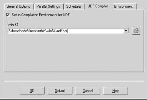
Figure 7.15 ANSYS FLUENT launcher window: UDF tab settings menu (https://hpc.nrel.gov/users/systems/winhpc/tips/ansys-fluent).
14. What are cores and sockets of nodes?
a. Core: Refers to a single processing unit capable of performing computations. A core is the smallest unit of allocation available in HPC Server 2008.
b. Socket: Refers to a collection of cores with a direct pipe to memory. It is the physical CPU chip. Each socket contains one or more cores. Note that this does not necessarily refer to a physical socket, but rather to the memory architecture of the machine, which will depend on your chip vendor.
c. Node: Refers to an entire compute node. Each node contains one or more sockets (Figure 7.16).
d. Specifying which nodes/sockets/cores for FLUENT runs? You can specify which nodes, sockets, or cores to run on by selecting the option on the Scheduler tab for Cores, Sockets, or Nodes (Figure 7.16).
– Cores If you choose two cores, it will spawn one core on one node and one core on another.
– Sockets If you choose two sockets, it will spawn two cores on one node.
– Nodes If you choose two nodes, it will spawn on all cores on two available nodes. Note: No other jobs or tasks can be started on that node.

e. Specifying specific cores on nodes: In the Environment tab in the FLUENT GUI, add the following environment variable:
CCP NODES = %CCP NODES% -cores # (where # is the number of cores you want to use on each node) (Figure 7.17). For example, if you were to choose CCP NODES = %CCP NODES% -cores four, it would spawn four cores on each of the nodes.
f. It is sometimes confusing to know when to use cores, sockets, or nodes. In general, the rule is:
Use core allocation if the application is CPU-intensive; the more processors you can throw at it, the better. Use socket allocation if memory access is what bottlenecks your application’s performance. Because the amount of data that can come from memory is what limits the speed of the job, running more tasks on the same memory bus will not result in speedup, because all of those tasks are fighting over the path to memory.
Use node allocation if some node-wide resource is what bottlenecks your application. This is the case with applications that rely heavily on access to disk or network resources. Running multiple tasks per node will not result in speedup because all of those tasks are waiting for access to the same disk or network pipe.

15. Some key facts
a. The unit type set on your job also applies to all tasks in that job.
b. You cannot have a job requesting four nodes with a bunch of tasks requesting two cores each.
c. You can still use batch scripts or your applications mechanisms to launch multiple threads or processes on the resources your job is allocated.
d. By using these correctly, you can improve your cluster use because jobs are more likely to get only the resources they need.
4.2. Troubleshooting FLUENT/HPC Issues
4.2.1. Windows 7: Specific Issues
1. Turning User Account Control on or off
User Account Control can help prevent unauthorized changes to your computer. It works by prompting you for permission when a task requires administrative rights, such as installing software or changing settings that affect other users.
b. Click Turn User Account Control on or off. If you are prompted for an administrator password or confirmation, type the password or provide confirmation.
2. Disable IPv6: IPv6 is the latest address protocol that will eventually replace IPv4. From Windows Vista onward, it has been kept enabled by default, but IPv6 is not yet common and many types of software, routers, modems, and other network equipment do not yet support it, including ANSYS. It is recommended to disable this protocol. Details can be viewed at [1] for disabling the IPv6 protocol.
3. Error: “job” is not recognized as an internal or external command, operable program, or batch file.
Problem Description: When trying to launch FLUENT from a Windows 7 client to a Windows 2008 HPC Server R2, you receive the following error in the FLUENT window:
“job” is not recognized as an internal or external command, operable program, or batch file.
Explanation: Windows has a 260 character limit in the PATH variable. When installing Microsoft HPC 2008 R2 Client software, it appends the bin path to the beginning of the PATH system variable. When the 260 character limit is reached, it throws the following entry (the bin path of the HPC client software) in the FLUENT window. To verify whether this is the root cause of the error thrown, type: path in a command window. It should confirm that the output of path is missing the path to the HPC client bin directory.
Resolution: Trim the System PATH variable so that it does not exceed the 260-character Windows limit.
4. FLUENT hangs when launching
You launch FLUENT and the FLUENT window reports “Waiting for CCP Scheduler @headnode ...” and hangs.
Resolution 1: The most likely reason FLUENT is hanging at this point is there is a username and/or password issue on any one of the compute nodes. The resolution is to clear the cached password and reset the password (Figure 7.18). If this is not the case, look at Resolution 2.
Clearing the Cached Password:
Resolution 1:
1. Open up the HPC job manager.
2. Open the Options menu.
3. Choose “Clear Cached Job Credentials.”

Resetting the Password
1. Open up the HPC Job Manager
2. Open up the Actions menu, Job Submission, New Job
3. Choose Task List in the left panel
4. In the command line box, type: cmd.exe
5. Choose Save, then Submit
6. You will be prompted to enter and save your password
7. Restart ANSYS FLUENT
Resolution 2: This behavior could also be caused by the order of the network bindings. Make sure that the private NIC is listed first in Adapters and Bindings.
5. An ANSYS FLUENT job seems to run indefinitely within the HPC Job Scheduler when running in batch mode
Make sure that you have specified a working directory before launching ANSYS FLUENT and that the directory is shared. This directory must also be mapped and you must use the mapped drive letter in the working directory text box.
6. Error when trying to write out a FLUENT case or data file
Check the order of the network bindings on the head node. The private network binding should be the first in the list (on top). The preferred network binding order is: private, Infiniband, MPI.
7. Launching FLUENT from a compute node is starting up slowly
Sometime when ANSYS FLUENT is launched on a compute node or a client machine, it takes a long time to open. The remedy is to check the order of the NIC cards on all nodes on the cluster. The private NIC should be listed first.
8. Slow read or write times with large case and data files
Table 7.2
| Interconnect | Latency (microseconds) | Bandwidth (millions of Bits per second) |
| GigE | 50 | 100 |
| Winsock direct | 15 | 800 |
| Transmission Control Protocol/Internet protocol | 45 | 200 |
| IBAL | 5 | 1000 |
9. Parallel Performance Issues
For optimal FLUENT performance, low-latency is essential. Bandwidth is the term used to describe the amount of data that can be transferred over a network cable or network device in a fixed amount of time. Bandwidth is measured in bits per second or in higher units such as millions of bits per second. Latency refers to any of several kinds of delays typically incurred in processing network data. A so-called low latency network connection is one that generally experiences small delay times, whereas a high latency connection generally has long delays. Once ANSYS FLUENT is launched in the ANSYS FLUENT window, type: (bandwidth # # “ ”), where the first # would be the first node on cluster 0 and the second # would be the last node on the cluster you are using to run ANSYS FLUENT. For example (bandwidth 0 7 “ ”) can be used to measure the bandwidth and latency between nodes 0 and 7 (eight cores). It is expected that you will see similar results based on Table 7.2. If not, running the bandwidth command again using one node at a time is recommended—for example (bandwidth 0 1 “ ”), (bandwidth 0 2 “ ”), (bandwidth 0 3 “ ”), etc.—until the node that is experiencing a network problem is identified.
..................Content has been hidden....................
You can't read the all page of ebook, please click here login for view all page.