2 |
What Is Digital TV? |
| CHAPTER |

FIGURE
2.1
Digital TV opens up a world of new possibilities.
TV transmissions contain a lot more information than radio broadcasts. The analog 625 line video signal contains about 250 times more information as a pure audio signal. The fact that a video signal requires this large amount of information has always been a problem for TV distribution.
Unlike an audio signal, the video signal does contain a lot of repeated information, since two consecutive frames of a transmission contain very similar information. This repeated information may be used to decrease the amount of information that has to be transferred from the transmitter to the receiver. However, in order to be able to extract the essential parts of the information, we need computers to process the TV signal and carry out all the necessary calculations. Since computers work with digital signals, we have to first convert the analog signal into a stream of digital bits before computers can reduce the amount of information. This process is complex, but it makes it possible to transmit eight to ten TV channels using a satellite transponder that before only had the capacity for one single analog signal. Using the same kind of techniques, it is also possible to fit a two-hour movie on a comparatively small DVD disc.
SHANNON'S INFORMATION THEOREM
There are certain natural laws that put limitations on how information may be transferred. Shannon's information theorem is such a natural law, saying that all transfer of information is limited by two factors: the received amount of signal power and the bandwidth of the channel used for the transmission. This is a phenomenon that should be regarded as a law of nature and therefore is impossible to circumvent. The amount of received power is decided by the strength of the transmitter and the efficiency of the antenna used for reception. The bandwidth is the amount of frequency space that is occupied by the transmitted signal.
Actual radio signals are always limited in bandwidth as well as signal power. This applies to radio signals distributed by satellites, terrestrial transmitters and cable TV networks. If we want to increase the amount of information in the signal, we either have to increase the power of transmission, the amount of bandwidth or both. The alternative is to decrease the quality of the signal—something we probably wish to avoid.
When using satellite for distribution, there are several transmitters (called transponders) in each satellite. A transponder is limited in bandwidth and output power. A traditional satellite transponder has a bandwidth of about 30 MHz and may be used to transmit one TV channel. To transmit more than one TV channel through such a transponder, we must find a way to decrease the amount of information that is required for each TV channel.
The principles for reduction of unnecessary information have been known for long. The unnecessary parts containing repeated information has to be removed and a reduced compressed version of the signal has to be created. In the receiver the original signal has to be re-created from the compressed signal.
DIGITIZING A VIDEO SIGNAL
In order to be able to let a computer handle a TV signal we first have to get it digitized. When we have a digital signal it is quite simple to manipulate it as we wish. Getting the signal digitized means that the audio and video signals are represented by a series of digits, rather than any physical media. The digits are then sent to a receiver which has the ability to recreate the physical analog audio and video signals from this information. A digital signal contains a representation of the signal rather than the actual signal itself.
In the beginning of the twentieth century, tests using telegraphy to transmit pictures were made that are quite similar to our modern way of digital thinking. A transparent grid representing a coordinate system was put on top of a photographic image. Then the black and white squares representing the picture were read manually and converted into a series of dots and dashes that were telegraphed to the receiver. At the receiving end, the tedious process of filling the correct squares on a paper with a similar grid took place.
Today, we do not have to do this by ourselves. Modern analog-to-digital and digital-to-analog converters do this job in a quick and convenient way. Now, we are going to take a look at how this conversion between analog and digital and vice versa is done.
The name digital comes out of the word digit—digital transmission is the transfer of digits describing the signal. The receiver has the ability to retranslate these figures into the physical analog signal.
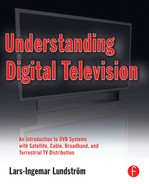
Analog-to-Digital Conversion
An electrical signal is electrical voltage that varies in time. By measuring the voltage at certain intervals, it is possible to get a series of measured values that approximately describe the signal. The device that performs the measurements is called an analog-to-digital (A/D) converter. The measured values can be transferred as digital numbers, bits, or a series of the digits 0 and 1. At the receiving end, these values are used to re-create the analog version of the voltage by means of a digital-to-analog (D/A) converter.
How Does the D/A Converter Work?
Re-constructing the digital signal to analog is done by translating each of the values included in the digital signal into an output voltage corresponding to each value. This creates a signal with a step-like shape rather than the soft waveform of the original signal. By passing the output signal through a low pass filter (a capacitor and a resistor), the quick transitions are filtered and the original signal is recreated as is shown in Figure 2.2.
FIGURE
2.2
Digitizing converts the signal into a series of 0 and 1 that describes the appearance of the signal. In this example, the signal is described by four bit samples that allow for the signal to be represented in 16 levels since four bits may be combined in 16 different ways.
MEASURING AND COMPRESSING DIGITAL VIDEO SIGNALS
When performing the A/D conversion, there are two things to keep in mind: The first parameter is the number of levels used to represent the signal to enable the correct reconstruction of the signal. Second, it has to be decided how often the signal must be measured and the values sent to the receiver. Every measured value can be regarded as a sample of the signal and is therefore called just “sample.” Really, we are just taking samples of the analog signal to create the digital signal.
Four digits describe every measured value. Four digits may be combined in 16 different ways: 0000, 0001, 0010, 0011, 0100, 0101, 0110, 0111, 1000, 1001, 1010, 1011, 1100, 1101, 1110 and 1111. In this case, it is said that the A/D converter has a resolution of four bits. However, 16 levels are not enough to describe a full quality video signal. Most A/D converters use seven- or eightbit resolution. For reference, eight bits corresponds to 256 levels, and ordinary bitmap image software provides an excellent grayscale picture if the pixels are described by 8 bits. Audio requires much better dynamic than could be achieved by 8 bits and 256 levels. The audio of a CD record is stored in 16-bit samples. This corresponds to 65,536 levels.
When it comes to the question about how often to measure, or sample the signal, there is a special theorem, the Sampling Theorem. According to the Sampling Theorem, it is necessary to sample the signal twice as many times as the highest frequency of the signal being digitized. For example, an audio signal must be sampled (or measured) at least 40,000 times per second if the bandwidth is 20 kHz.
In a video signal with a bandwidth of 5 MHz, at least 10 million samples have to be taken every second in order to get a stream of bits containing enough information for the receiver to reconstruct the signal. Of course, the result is an immense amount of bits every second. The following calculations show what this means when digitizing a video signal.
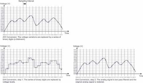
A standard European 625-line signal consists of 576 active lines that form the picture. Every line is considered to consist of 720 pixels (pixel, short for “picture element”). The total number of pixels in a picture is 414,720 (576 x 720).
As we discussed earlier, 8 bits are required to describe each pixel by 256 different levels between black and white. This means 8 x 414,720 bits = 3,317,760 bits required to describe each picture. The picture rate is 25 pictures per second; that results in 25 x 3,317,760 = 82,944,000 bits per second or 82,944 Mbit/s.
As we discussed in the previous chapter and as shown in Figure 2.3, a color picture really consists of three parallel pictures (red, green and blue). The final conclusion is that 3 x 82,944 Mbit/s = 248,832 Mbit/s.
FIGURE
2.3
A color pictue really consists of three pictures (red, green and blue). Alternatively, the picture may be represented by the black-and-white Y signal along with the U and V color difference signals. (See color plate.)
A similar calculation can be made on a North American TV signal comprising 486 x 720 pixels at 30 pictures per second. The resulting number of bits will be 486 x 720 x 8 x 30 = 83,980,800 bits per second (83,981 Mbit/s) for each of the three basic color components. As a total we get 251,942 Mbit/s.
In professional digital television, the analog signal is digitized using Y, U and V signals instead (see Chapter 1, “The History of Television”). The Y signal (black-and-white content) is sampled using 10 bits at a rate of 13.5 million samples per second. The color difference signals (U and V) are both sampled also using 10 bits but at half the sampling rate—6.75 million samples per second. In that way we can take advantage of the fact that the eye is less sensitive to resolution when it comes to the color content in the picture compared to the sensitivity to resolution in the luminance signal. The formula to find resulting bitrate will be the same as in the example above; 10 x (13.5 + 6.75 + 6.75) million bits per second equaling 270 Mbit/s.
However, 270 Mbit/s is much too much data to be transmitted in a practical way. A signal of this kind can be distributed inside a TV production company or stored on professional digital video recorders. But a satellite transponder (that previously could be used to distribute one TV channel) can only house between 38 and 44 Mbit/s, if QPSK modulation is to be used. The same problem exists in a cable TV channel, and the lack of bandwidth is even worse when it comes to terrestrial television where 22 Mbit/s in a conventional transmission channel is quite common.
The conclusion will be that uncompressed digital TV channels requires much more bandwidth than is the case for analog TV channels. Therefore we must find a way to compress the digital TV signal in a way that it requires less bandwidth. The uncompressed signal becomes more or less unusable when we leave the building of the TV station.
Note
There are, however, ways to distribute uncompressed video in optical fibers. These possibilities, however, are only used for professional purposes.
Compressing Digital Signals
In order to be able to handle the digital video signal, we have to go further in trying to minimize the amount of information in the signal. To solve this, a number of experts got the task to find new and smart methods to eliminate unnecessary information in digital images and digital video sequences. For this purpose, the expert groups JPEG and MPEG were formed.
Compressing Still Images
The Joint Photographic Experts Group (JPEG) got the task to develop a standard to compress digital still images. This was very important in order to be able to store images in computers as well as transferring pictures in between computers in an efficient way. Today the JPEG standard is used everywhere. The most common applications are in digital cameras and when distributing pictures over the Internet.
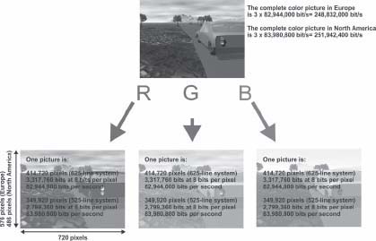
A picture consists of a number of pixels. The two pictures in Figure 2.4 each have a resolution of 540 x 405 pixels, giving a total of 218,700 pixels for each. You may choose different numbers of bits to describe each pixel. A common choice is to use 8 bits to describe the luminance level of a pixel. The choice of 8 bits makes it possible to describe one of 256 possible grayscale levels in between black and white.
A picture with 540 x 405 pixels in resolution will require 218,700 x 8 bits resulting in 1,749,600 bits or 218,700 bytes. (One byte is 8 bits.) Since a color picture consists of three pictures (RGB), three times as many bits are required to represent the color picture, i.e., 5,248,800 bits or 656,100 bytes. When I checked the sizes of the pictures in Figure 2.4, I found that both were about 640 kbytes when saved in the uncompressed bmp file format.
This matches up to our calculations quite well. An uncompressed picture with a certain number of pixels will always require the same number of bits and bytes, in this case 640 kbytes independent of the content of the picture. This is why the two images—though they show the subject in different perspectives—have the same uncompressed size.
Compressing a picture means that the picture file is recalculated using a certain algorithm (calculation rule) that takes several things into account. As an example, it may be possible to use the fact that a number of pixels that are located close to each other look a like and have the same value. In that case, it may be overkill to use 24 bits to describe each pixel and instead it may be enough to use 24 bits for the value of several pixels along with a less consuming description of where these pixels are located. In some cases this may result in a smaller image than one that describes each pixel separately.
It is possible to choose the compression level you want for the compressed JPEG file. As a general rule, it is possible to go down to about one-sixth of the original file size without affecting the quality of the picture in a noticeable way. On top of this, the compressed picture files will vary in size depending on the content in the picture (as is illustrated by Figure 2.4). For example, a large area of the same color, like the ball in Figure 2.4, would be considered one chunk of data that can be stored as a much smaller piece of data. Thus it is possible to use the fact that some pictures really contain less information than others and to reduce the need for bits and bytes in this way.
If the picture is completely black, there is only one level for all pixels in the picture. Then it would have been enough to tell that all pixels in the picture only have one value. I tried a completely black picture with the same resolution as the pictures in Figure 2.4 and ended up with a compressed file of just 4.06 kbytes.
On the other end of the spectrum, the worst picture to compress would be one where all pixels have different color and luminance levels. Such file would probably be just as big as an uncompressed file, at least if we had chosen a high-quality level for the compression process.
Fortunately, the world doesn't usually work this way and most pictures contain large areas where the pixels are more or less alike. For this reason, JPEG files are usually only one-tenth to one-fifth of the original file size. Otherwise the digital cameras would require five to ten times as large flash memories and it would take five to ten times as long to download pictures over the Internet.
FIGURE
2.4
The most common file format on the Internet and in digital cameras for image compression is JPEG.
Compressing Moving Pictures
The JPEG format is developed for compression of digital stills. When this task was done, another group of experts, the Moving Pictures Experts Group (MPEG), got a similar task to do the corresponding work for standardizing compression formats for moving pictures. The aim was to make it easier to handle movie clips in computers and to transfer these files between computers in a less bitrate-consuming way.
The first part of the standard got ready in the beginning of the 1990s and is called MPEG-1. The compression algorithm is optimized for video files with a small bandwidth below approximately 2 Mbit/s.
The compression is based on the principle of analyzing each picture in the video signal and to find the differences in between the pictures. On the Internet, you often watch TV in small windows which use fewer lines than conventional TV, which reduces the bitrate demand even more. This made it possible to transmit low bitrate TV through telephone lines using ordinary modems. And of course, broadband connections provided even better results.
MPEG-1 has been very popular for distributing video clips on the Internet but the standard can not achieve the performance that is required to replace analog television.
The next step was to establish a standard that could be used for standard television, thus completing the dream about distribution of digital TV via satellite, cable and terrestrial transmitters and even to store video on DVD records. The second standard, MPEG-2 is optimized for higher bitrates from 2 Mbit/s and up. You could say that MPEG-2 picks up where MPEG-1 ends. In MPEG-1 there are quite some problems in describing movements in the video content. Therefore apart from providing higher bitrates, MPEG-2 is also supporting motion compensation resulting in soft and natural movements in the picture.
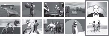
MPEG algorithms are based on using groups of pictures (GOP) as is shown in Figure 2.5. In this example a GOP makes up half a second of video. Each GOP contains 12 pictures. However it is possible to select different numbers of pictures and this example is only to explain the basic concepts of video encoding. In reality the process is more complicated.

FIGURE
2.5
MPEG algorithms are based on using only the difference in information between the original pictures in the video file. In this example only one of every 12 pictures is saved or transmitted (marked in red). (See color plate.)
In this example there are two GOPs per second. In each GOP, only the first picture is a complete picture. Then the remaining 11 pictures are calculated from the first picture and only the difference between the original pictures is stored with the file. All other pictures are recalculated at the receiving end. If there is a change of scenes in between two GOPs, a new GOP is started immediately and an “extra” full picture is transmitted.
To make it all even more economical, the first picture in each GOP is JPEG-compressed. The original 270 Mbit/s signal is reduced to a compressed bitrate of 3 to 4 Mbit/s and still it remains at an acceptable quality level.
Figure 2.6 shows the difference between two consecutive pictures in two different scenes. Black parts of the pictures do not contain any different information, while brighter areas show information that is different in the two consecutive frames. Thus the need for capacity (bitrate) varies all the time when using MPEG compression.
Quite obviously, the digital receiver will be much more complex than earlier analog receivers working with real time signals only. Signal processing at this level must, for practical reasons, be done using a computer. It is a software issue to be able to restore the original signal at the receiving end and most of the decoder is software that is housed in an integrated circuit. At the transmission end the compression equipment—the encoder—is a very complex device.

FIGURE
2.6
The difference between two consecutive pictures depends on the amount of movement in the picture. These two pictures show the differences between some of the pictures in Figure 2.5.
Encapsulating Into Transport Stream Packets
We have now achieved a compressed video signal at a bitrate of about 4 Mbit/s. However we also need to transmit audio and possibly teletext signals. The audio is compressed in an audio compression format called Musicam. The audio encoding can be chosen at different bitrates just as the video compression. A common bitrate for a stereo pair is 256 kbit/s, however also 192 kbit/s or 128 kbit/s may be chosen. A digital TV signal consists of at least two or three signals—one video, one audio and perhaps also a teletext signal at 200 kbit/s.
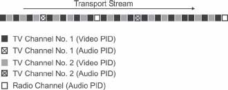
Fortunately it is quite easy to combine several digital signals into one single signal. This process of combining the signals is called multiplexing. However, in order to multiplex the signals, each signal first has to be divided into packages. By transmitting the packages at different intensities, it is possible to mix fast signals (video) with a high bitrate with those having a low bitrate (audio and teletext), as in Figure 2.7.
FIGURE
2.7
Audio and video are in separate bit streams. By using different intensity for the packets belonging to different signals it is possible to mix more capacity demanding signals as the video with less demanding content as audio or teletext channels.
The packages into which the signals are divided are called transport stream packets (see Figure 2.8). The length of each packet is 188 byte. The first four bytes in each packet is called the header. The first byte in the header contains a synchronization word that is unique and that indicate the start of a new packet.
This byte is followed by the Package Identification Data (PID), two bytes with the identity of the signal to which the packet belongs. This is the label that makes it possible to separate the signals again (called demultiplexing) at the receiving end. The fourth byte contains a counter that indicates the order between the packets that belong to a specific signal. This counter is also a way to determine if any packet has been lost on the way to the receiver. The remaining 184 bytes contain useful information, the payload. Together, these packets form the transport stream.

FIGURE
2.8
The bit streams are divided into smaller packets each consisting of 188 bytes. The first 4 bytes are the header which is a tag identifying to which bit stream the packet belongs.
Splitting the information into packets achieves several advantages, in addition providing the ability to combine signals with different bitrates. The signal also becomes less sensitive to noise and other disturbances. Radio disturbances are actually short spikes of power and often have a very short duration. If one packet is disturbed, the receiver can reject that specific packet and then continue to unpack the rest of the packets.
IP traffic across the Internet is two-way communication. If a packet is lost, the sender is notified and can retransmit that specific package. Broadcasting signals are fed through a one-way distribution chain and no retransmission of lost packages can be done. To compensate for this, we have to use error protection. Error protection means adding extra bits according to clever algorithms. These extra bits make it possible for the receiver to repair the content of broken packages. Therefore to secure the signal even further, an additional 16 bytes are added to each individual packet. The information in these bytes is calculated based on the information in the 184 bytes of payload. The calculation is conducted using the Reed-Solomon encoding algorithm that, in this case, is configured to be able to correct up to eight errors in the 184 bytes of payload. If there are more than eight errors the complete packet will be rejected.
System Information
It is not enough to deliver packets containing audio and video. The receiver also must be able to know which packets contain what data. This is solved by including system information in the transmitted signal. The system information is a number of tables that are distributed in separate bit streams. The most important table is the Program Association Table (PAT), and this signal always has the packet address PID=0. The first thing the receiver has to do is to find the PAT and read the content of the table. In the PAT, there are references to which PID addresses contain the second-most important kind of table, the Program Map Table (PMT). Each radio or TV channel that is distributed in the transport stream is called a “service” and each service has its own PMT. In the PMT of each service, the receiver can find the PID for each component of that service. For a TV channel, that would be the PIDs that are associated with the video, the audio and the teletext information bit streams.
DIGITAL VIDEO BROADCASTING
Digital Video Broadcasting (DVB) is the standard for digital broadcasting that was first adopted in Europe. The original standard was based on MPEG-2 encoding of the video and Musicam encoding of the audio. In addition to referring to these standards, the DVB standard also tells how to combine several services as radio and TV channels in a multiplex. This is important if you wish to distribute the signal using satellite, cable or terrestrial transmitters. The DVB standard also contains rules for how the signals are to be distributed through three kinds of distribution media; DVB-S (Satellite), DVB-C (Cable) and DVB-T (Terrestrial)
In the United States there are some other digital TV systems, but DVB has proved to work very well and is now adopted in the U.S. and other parts of the world. The DVB standard also includes other kinds of tables containing information to the viewer about what programs are on right now and what comes up next.
Statistical Multiplexing
DVB is very much about how to putting several radio and TV services together to form a program bouquet contained in a transport stream.
We have already seen that the need for a large capacity in a video signal that varies all the time depending on the video content. In a multiplex of six to eight channels not all of the channels will need maximum capacity all the time. Sharing the capacity of a multiplex among the channels—giving the most bandwidth at any given moment to the most demanding channel at that moment—optimizes the use of the available capacity.
This is called statistical multiplexing and increases the usable capability by approximately 20 percent. In this way, a satellite transponder (having a capacity of 44 Mbit/s) that normally houses eight channels will instead be capable of handling 10 channels. A terrestrial DVB multiplex with a capacity of 22 Mbit/s will be able to handle five instead of four TV channels.
An optimum way of using statistical multiplexing is to combine channels containing lots of motion (such as sports channels and music video channels) with less demanding channels (such as news channels and channels which contain a lot of studio content) as in Figure 2.9.
FIGURE
2.9
Statistical multiplexing takes advantages of the variations in motion and capacity demands across the channels in a multiplex. (See color plate.)
Receiving the DVB Signal
Figure 2.10 illustrates the basic principles for treating the digital signal inside a digital set-top box. This is a visualization of how the signals are routed through the receiver, but of course, in reality, you can't follow the signals in this way. Large portions of the device are based on a computer, some memory and rather complex software.
All receivers have some kind of a front end. This front end, or tuner, is used to choose the transmission channel that is to be received from the radio spectrum. The transmission channel may be a signal from a satellite transponder, a cable TV channel or a terrestrial channel that contains a multiplex of digital radio or TV channels. The tuner is designed according to whether it is to receive signals from satellite, cable or terrestrial transmitters.
This design also applies to the demodulator that follows the tuner. The demodulator is different depending on what transmission media is to be used but its general purpose is to restore the transport stream.

FIGURE
2.10
The digital receiver contains a number of basic functions. The tuner selects the desired transmission channel. The demodulator restores the transport stream. Then the demultiplexor sorts out the signal into its original components.
At the output of the demodulator, we obtain the transport stream. After this point, the signal is treated exactly the same regardless of what media has been used for transmission (satellite, cable or terrestrial).
The heart of the digital receiver is the demultiplexor. In the demultiplexor, the different tables in the transport stream are read and the receiver learns how the received signal is arranged. At the output of the demultiplexor, the different bit streams of the service that has been selected by the viewer are sent to the appropriate decoder. The information contained in the video packets is sent to the MPEG-2 decoder. The content of the audio packets are sent to the Musicam decoder and the teletext information is sent to the teletext system. In digital receivers, the teletext pages (which only exist in Europe) are stored in memory so the viewer can instantly select the desired page. Another alternative is to reinsert the teletext pages into the analog composite video signal and to use the teletext system that is integrated in the TV set. Sometimes both these methods are used simultaneously.
If the transmissions are encrypted, the decryption process also takes place in the demultiplexor system. Then the demultiplexor is connected to a CA (conditional access system) and the card reader that is associated with that part of the device.
There are at least three different methods for connecting the digital receiver to one or more TV sets. The simplest and giving the best results is to use the RGB-signals that may be obtained from the scart output. The scart connector, covered in more detail in Chapter 9, is a 21-pin connector with separate connections for the three color components of the color video signal. A scart cable has to be used to connect the digital receiver to the TV set to keep the three color signal components, R, G and B, separated all the way from the TV station to the set. This ensures optimum performance. Even the stereo audio channels are included in the 21-pin scart connector in a convenient way. The scart connector is a typical European device.
However, a video recorder can not handle RGB signals. The digital receiver must also have a composite video output containing a PAL signal. For this reason there is a composite video encoder in the device. The composite video signal is also available on one of the pins in the scart connector. Composite video can be used in most video devices as well as in all DVD recorders. European digital receivers always have the composite video integrated in the scart connection. However there are Asian and American receivers that also have a composite video output on an RCA connector.
Other interface options for connecting HDTV digital receivers
The introduction of plasma and LCD TV sets has introduced some new interfaces for the video signals. In the flat-panel TV sets as well as video projectors, there are also connections for component video. This interface consists of three RCA outputs carrying the luminance, Y signal and the two color difference signals. The component interface has been in use for video projectors for a long time and is also quite common in more expensive DVD players and recorders. Component outputs allow for progressive scanning, which is discussed further in Chapter 11, “The Home Cinema.”
There are also other important digital interfaces, such as DVI and HDMI, that allow for digital connection between the receiver and the TV set. These interfaces are available in expensive DVD players but only HDTV receivers carry these interfaces so far. The same applies to the component video interface. We will take a closer look at this in Chapter 12.
High definition signals require either component, DVI or HDMI connections between the digital receiver and the display system.
Scart cables are quite thick and tough to handle if they are not quite short, so the signals may only be distributed to devices that are located quite close to the receiver. For this reason, the receiver usually has an integrated modulator (a small TV transmitter). Using the RF output of digital receiver makes it possible to connect the receiver through the aerial input of the TV set. Then ordinary coaxial cables may be used to distribute the signal to one or more TV sets in other rooms. A disadvantage of doing this is that the picture quality is lower and the audio will be restricted to mono.
PICTURE AND SOUND QUALITY
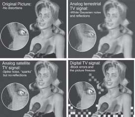
Bad analog signals result in noisy pictures and noisy sound. There is a big difference between analog and digital signals when it comes to distortions. Analog terrestrial TV is subject to reflections and white Gaussian noise. Analog frequency modulated signals are subject to spike noise but there are no reflections.
In digital TV, the audio and video is always the same, as long as the signal is strong enough to allow for reception. If reception is bad audio and video disappears completely, leaving a black screen and no audio at all.
However there is a thin window between useful reception and loss of signal. In this range you will get errors, called pixilation, in the picture. Pixilation is not really the right word. What you actually see on screen are the so-called “macro blocks” of the picture. When the picture is compressed for transmission, the encoder divides the picture into small squares, macro blocks. If the signal contains too many errors, the MPEG-2 decoder has problems in restoring some of the macro blocks in the right way, such as in Figure 2.11. You may also see freezing effects in the picture.
FIGURE
2.11
Digital TV is different from analog TV when it comes to distortions. Either you have a perfect picture or no picture at all. However there is a very narrow range between acceptable reception and loss of signal where you will see blocking effects in the picture. (See color plate.)
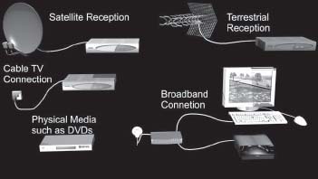
The DVB standard is used for satellite, cable and terrestrial distribution (see Figure 2.12). When watching TV over the Internet, MPEG-1 is still very much in use. In the last two years, IP-based TV (IPTV) through broadband connections has started to become the fourth way of distributing TV. In this case, the old copper wiring that once was used for telephony is used for media. Since higher bitrates may be used, MPEG-2 signals are encapsulated in IP packets instead of DVB packets. We will return to this in Chapter 7, “Digital TV by Broadband.”
FIGURE
2.12
The digital TV signals may be transported and stored using any kind of distribution media. The MPEG standards are in use everywhere, even on physical media, such as DVDs.
MPEG-4: HDTV COMPRESSION
MPEG-2 is the compression standard that is used for DVB standard definition TV distribution. MPEG-2 is also used for high definition terrestrial broadcasting in North America and for some satellite based channels. However there is a new compression standard that will change everything.
MPEG-4 is the successor of MPEG-1 and MPEG-2 and may be used at all bitrates from 10 kbit/s to several Mbit/s. The new standard could be said to combine the best of performance in MPEG-1 and MPEG-2 and the same format can be used for signals having very low as very high bitrates. Therefore MPEG-4 is suitable for low bitrate Internet TV as well as standard definition and high definition TV. On top of this, MPEG-4 is much more efficient that MPEG-2. With MPEG-2, a bitrate between 3 to 5 Mbit/s is required for standard TV while MPEG-4 can produce an acceptable quality at bitrates down to 1.5 Mbit/s, if cutting-edge technology is used. MPEG-4 is also easier than previous formats to combine with computer graphics.
MPEG-4 is definitely a better way to compress video signals than the earlier standards. However, it seems that we are already stuck with MPEG-2. For standard definition TV, an immense number of MPEG-2 DVB compliant devices have already been sold.
Using MPEG-4 over the Internet is much easier since you only have to download a new codec for your software media player. Changing the standard in set top boxes is much more difficult.
But when it comes to HDTV, the bandwidth savings of MPEG-4 is very large. Today's European HDTV transmissions are carried out using the MPEG-2 format via satellite. It takes about 16 Mbit/s per TV channel to be able to handle HDTV in this way. Changing to MPEG-4 will require only 6 to 8 Mbit/s per channel. No doubt HDTV will be the most important use of MPEG-4 during the years to come. MPEG-4 can be carried inside DVB packets just as MPEG-2 is.
Another example of MPEG-4 is the DivX-format, which is based on this technology.
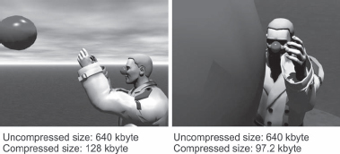
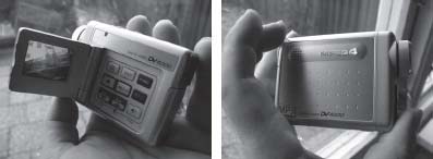
There are also some flash memory video cameras that use MPEG-4 to provide increased recording time, like the one in Figure 2.13. These video cameras provide video recording with devices that do not have any moving parts, so the power consumption is less and they are very small. And all this is really only due to the fact that they are using efficient compression algorithms. In the long run these smaller MPEG-4 cameras will replace cameras with cartridges and records.
FIGURE
2.13
This tiny, flash-memory-based video camera from Mustek is an example of an MPEG-4 device.
WHY CHANGE TO DIGITAL TV?
Of course people who have been satisfied with analog television might wonder why they should invest in digital receivers to view ordinary TV programs. Really, they might argue, there are analog systems providing acceptable picture and sound.
However this is not the complete truth. Those who try digital TV quite soon experience the increased performance. This could be compared with the introduction of the DVD. Having tried a DVD recorder, there is no way back to the VHS machine. People getting used to the superior performance from DVD recordings also want to be able to watch TV without noisy pictures and with a clear noiseless sound. This is also the reason why people are prepared to pay extra for the DVD version of a movie rather than the VHS edition. The same thing happened when the CD was introduced. People soon bought CDs for twice the price as an old LP.
Digital video always provide a guaranteed level of performance in the picture as well as in the sound.