| Subtractive Synthesis | 1 |
Subtractive synthesis has been used on thousands of records, and, in spite of its continued evolution, its essence remains the same at the very core. The reason it has continued to inspire musicians is because it can take electronic sounds and give them life through filters and envelopes that breath motion into the lifeless in order to create new, organic, exciting sounds or mimic the natural organic progression of acoustic instruments. Sounds are nothing less than magical when programmed by the experienced user.
The Synthesizer Database
When conducting research for this book, we thought it would be interesting to examine as many of the commercially available synthesizers that was physically possible in order to come up with averages of their capabilities. We compiled a comprehensive database that featured as many synths as possible (around 800 individual instruments) and outlined, in depth, their functionality. We examined things like the number of oscillators and low frequency oscillators, the number of filters and filter shapes, the number of envelope generators and their capabilities, the various wave shapes the synth could produce, the modulation routings, and the inclusion of various forms of performance control. We then averaged this database in relation to synthesis format so that we could provide you with the average number of synthesizers that feature a specific parameter throughout this chapter. As you will see in the coming pages, each parameter of subtractive synthesis will be complimented with the average percent of synthesizers that feature that particular function. So without further ado, let’s begin with subtractive synthesis.
Subtractive synthesis starts with a sound. This sound is then filtered, modulated, mangled, and mashed, resulting in something beautiful. The starting sound comes from what is known as an oscillator, which is the heart of any synthesizer. Often underrated, the design of a synthesizer’s oscillator ultimately determines the status that a synthesizer holds in history. Every parameter on a subtractive synthesizer—be it a filter, an envelope generator, a low frequency oscillator (LFO), or an amplifier—relies on the oscillator or oscillators in order to stand out amongst the vast and ever growing market of synthesizers. Take a MiniMoog for example; just listening to a single oscillator playing a triangle wave with no envelopes, resonance, or modulation is enough to send shivers down someone’s spine. An average triangle wave is rather boring, but, for some reason, a MiniMoog’s triangle wave connects with its users and instantly inspires them to reach out and turn every knob, opening up a world of creativity. The fact that every single waveform on a MiniMoog elicits this same response is the very reason that the MiniMoog became one of the most famous subtractive synthesizers in history.
Based on the information collected, subtractive synthesizers feature three oscillators on average.
So what makes an oscillator so iconic? The functionality and features of an individual oscillator definitely play a role, but the sound of the individual waveforms an oscillator creates is where its iconic status ultimately rests. Let’s examine what makes up a waveform as well as what makes a sawtooth wave sound different from a triangle or a square wave.
Harmonics
A waveform consists of a fundamental frequency and a series of additional frequencies called harmonics. The fundamental frequency is the frequency of the note being played. For example, the middle “A” note has a fundamental frequency of 440Hz, but most instruments do not produce just a single frequency. When a pianist strikes the middle “A” note on a piano for example, 440Hz is not the only frequency that is heard. Many higher frequencies, called overtones, emit from the piano as well. In a piano, these overtones are caused by the way the string vibrates, the resonance of the body of the piano, and other strings resonating in conjunction with the string being struck. The frequencies above 440Hz that emit from a piano when the middle “A” is struck are multiples of the fundamental frequency; these are called harmonics. The harmonics are produced in what is called the harmonic series, which is a pattern of harmonics that occurs naturally with musical instruments. In the harmonic series, the first harmonic is the fundamental frequency. Using our “A” 440 example, 440Hz is the first harmonic of the harmonic series. The second harmonic is twice the fundamental, or 880Hz. The third harmonic is three times the fundamental, or 1320Hz, etc.
Although the harmonic series is present in every instrument or sound, the amplitude at which these harmonics are heard vary from one instrument to another due to the material the instrument is made of, as well as the way in which sound is generated (strings, resonant tubes, membranes, etc.). These differences explain why instruments have unique sounds; a piano sounds different from a tuba which sounds different from an accordion and so on and so forth. This difference in tonal quality is called timbre. Synthesizers are such an attractive instrument because they can change timbres in an instant. The user is free to emulate a natural instrument or make a sound that is so earth shattering that it questions the very meaning of what is musical, all with the turning of a few knobs.

Figure 1.1 The harmonic series as demonstrated with vibrating strings.
Waveforms
When dealing with synthesizers, each waveform has a unique sound due to the varying harmonic content that is produced. This is why a square wave sounds worlds apart from a sine wave. Let’s take a look at the harmonic content of the most common waveforms found in subtractive synthesis in order to better understand the tonal quality of each of these waveforms.
Sine waves are the most simple of the waveforms. They contain only the fundamental frequency and no harmonics. A sine wave is something that is unique to synthesis because there are no nonelectronic instruments capable of such a tone. Just because a sine wave is simple does not mean that it is boring or less than useful. A sine wave, when placed in the audio spectrum correctly, will rumble the floors of a venue or pierce through the densest of mixes.

Figure 1.2 The standard synthesis wave shapes.
Take a Roland TR 808 drum machine for example. The 808 uses analog subtractive synthesis to create its drum sounds. The iconic kick drum sound of an 808 has destroyed subwoofers and left an everlasting impression on anyone who has heard it thanks to its huge sine wave “ring” on the falling end of its sound. Sine waves have also long been coveted as a foundation for the largest of synth bass sounds. The extremely memorable bass sound on Nine Inch Nail’s “Closer” would not have been possible without a sine wave in the mix.
Based on the information collected, 34% of subtractive synthesizers feature audio oscillator sine wave generation.
Triangle waves sound fairly similar to sine waves but with a bit more harshness. A triangle wave contains the fundamental frequency as well as all odd harmonics. This means that a triangle wave is made up of the first harmonic, or fundamental frequency, the third harmonic, the fifth harmonic and so on. The rate at which the higher harmonics drop in amplitude is proportionate to the inverse square of the harmonic number. For example, the third harmonic is 1/9th the amplitude of the fundamental and the fifth harmonic is 1/25th the amplitude of the fundamental. This rapid decline in the amplitude of the harmonics causes very few harmonics to be audible, which is why the triangle wave sounds similar to the sine wave. The few harmonics that are audible separate the triangle wave from the sine wave. As stated earlier, the MiniMoog’s triangle wave is one of the many reasons the MiniMoog is still being talked about today. When overdriven into a filter, the triangle wave adds everything a sine wave is capable of adding to a sound, but also adds a new dimension of grit and glam that is only attainable through this means of synthesis.
Based on the information collected, 48% of subtractive synthesizers feature audio oscillator triangle wave generation.
Sawtooth waves have a very distinct, raspy sound quality. A sawtooth wave can scream and it pierces through any sound it’s up against. At the same time, however, a sawtooth can be filtered back to create soft, delicate, and smooth sounds that can be placed in the most “moody” of R&B songs. Sawtooth waves get their name from their resemblance of a physical sawtooth when viewed on an oscilloscope. Unlike a triangle wave, a sawtooth wave contains the fundamental frequency as well as both even and odd harmonics. The rate at which the harmonics drop in amplitude is inversely proportionate to the fundamental rather than the inverse square of the fundamental like in a triangle wave. This means that the second harmonic is 1/2 the amplitude of the fundamental, the third harmonic is 1/3 the fundamental, the fourth harmonic is 1/4 the fundamental and so on. Due to the slower decline in amplitude of the harmonics as well as having the even and odd harmonics audible, the sawtooth wave is extremely rich sounding and is very useful in subtractive synthesis. Due to the rich and harsh tonal quality of the sawtooth wave, it is extremely well suited for re-creating bowed string sounds such as cellos and violins and, as stated earlier, piercing lead and punchy bass synth sounds. The sawtooth wave is a staple amongst synthesizers and no instrument besides a synthesizer can come close to re-creating it.
Based on the information collected, 68% of subtractive synthesizers feature audio oscillator sawtooth generation.
Ramp waves, or reverse sawtooth waves, are simply backwards sawtooth waves. Rather than the wave peaking and then sharply sloping down, the ramp wave sharply slopes up and then peaks and drops back down to zero. The ramp wave contains the exact same harmonic content as the sawtooth and sounds identical. However, it is when using the oscillator as a control source for an LFO or as an envelope that ramp waves differentiate themselves from sawtooth waves and become one of the most overlooked and coveted of the waveforms. Mark Mothersbaugh of DEVO sent his MiniMoog back to the engineers at Moog in order to have it customized in order to produce a ramp wave. Mark’s customized MiniMoog can be heard in the extremely memorable synth parts of DEVO’s “Smart Patrol/Mr. DNA.”
Based on the information collected, 41% of subtractive synthesizers feature audio oscillator ramp wave generation.
Next to sawtooth waves, square waves are the most recognizable of the waveforms. Square waves have a rich but hollow sound quality. Their name is derived from their square-like appearance on an oscilloscope. Like the triangle wave, square waves are made up of the fundamental frequency as well as all odd harmonics meaning they contain the first harmonic (fundamental), third harmonic, fifth harmonic, and so on. Unlike a triangle wave however, the rate at which the harmonics drop in amplitude are inversely proportionate to the fundamental. This means that the third harmonic is 1/3 the amplitude of the fundamental, the fifth harmonic is 1/5th the fundamental, the seventh is 1/7th the fundamental and so on. Because of the square wave’s richer sonorities of harmonics, it imparts a full tonal quality to any synth sound that can only be described as legendary. Keith Emerson’s synth solo towards the end of Emerson, Lake & Palmer’s “Lucky Man” are perfect examples of what a square wave can add to a screaming lead line. The alternative band Passion Pit makes extensive use of the square wave on most of their synth parts throughout their entire catalog of music. The square wave is truly a synth staple and, for that reason, it can be found on almost 99% of synthesizers from the most basic and budget models up to the most expensive.
A pulse wave is, in essence, a variable square wave. Like a square wave, the pulse wave contains the fundamental and all odd harmonics with the same inversely proportionate harmonic amplitude drop. The difference is that the width of the wave in the positive and negative direction is variable. One of the most sonically pleasing and sought after sounds in synth history is created by modulating the width with an LFO. Typically, this variable width is continuously adjustable (from so narrow that it’s not audible to all the way up to a full square wave), but some synthesizers have set width amounts. The song “Warp” by The Bloody Beetroots and Steve Aoki makes great use of pulse width modulation.
Based on the information collected, 85% of subtractive synthesizers feature square or pulse wave generation.
A Note on “Hyper” Waves
Many current manufacturers are including variations of the basic waveforms into their synthesizer designs and are labeling these new variations with the descriptor “hyper”; such as “hyper-saw” or “hyper-square” waves. These new waveform variations typically use wave folding or wave multiplying technology in order to alter the tonal characteristics of these waves to give the user more possibilities for sound creation.
Wave folding technology works by “folding” the wave back on itself causing more harmonics to be present at different levels. Wave folding can be thought of as the opposite of a filter; whereas a filter takes harmonics away from a sound, wave folding devices add harmonics into a sound. Wave multiplying technology multiplies the wave and usually shifts the pitch of the multiplied waves. These features not only give the user more sonic capabilities, but can make a single or dual oscillator synth sound like it has more oscillators, which is a great benefit to some of the low-cost models. The extremely popular analog subtractive synth from Arturia, called the MiniBrute, utilizes these hyper waves for all of the waveforms of the single oscillator, which makes it an extremely powerful single oscillator budget synthesizer.
Another hyperwave generation technique that warrants a discussion is wave shaping. Wave shaping produces similar results to wave folding, but rather than folding the wave back onto itself, wave shapers actually change the shape of simple waves, which creates sharper corners and increases harmonic content. The most common use of wave-shaping technology can be found in guitar distortion pedals and fuzz boxes. The clean guitar signal present at the device’s input is amplified and forced to clip, which adds in newer harmonics, creating the distorted sound at the output. Wave-shaping technology is rarely seen outside the modular synthesizer world, but it is beginning to surface in some of the new analog synths due to the high demand for distorted synth sounds.
Different Types of Oscillators
Now that we have explored how oscillators and their waveforms make or break a synthesizer, let’s examine the different types of oscillators that are available. When dealing with subtractive synthesis, there are three main types of oscillators one can expect to encounter—voltage controlled oscillators (VCO), digitally controlled oscillators (DCO), and software-based oscillators. These three types of oscillators are by no means the only type found on subtractive synthesizers, but they are by far the most common. Similar to the waveforms themselves, each of these types of oscillators imparts unique features and tonal qualities onto the synthesizer.
Voltage Controlled Oscillator (VCO)
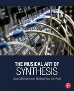
The VCO is an oscillator that gets its pitch information from voltage input. Although many people experimented with different types of ways to control oscillators in the early years of synthesis, Bob Moog is most often credited with introducing the voltage controlled oscillator. Moog’s early oscillators introduced the 1volt/octave standard found in most analog synthesizers both past and present. This standard divided a single volt into 12 parts to accommodate the 12-tone Western scale. This means that each half step is related to a 1/12-volt change. This 1volt/octave standard not only made it possible for synthesizers to produce tonal music, but also made it possible for synthesizers to communicate with each other. In the days before MIDI (and still today), analog synthesizers featured control voltage (C.V.) inputs and outputs. This means that a user could connect two or more synthesizers together and control each of them with a single keyboard. Bernie Worrell used three separate MiniMoog synthesizers connected through C.V. to achieve the gigantic synth bass sound on the Parliament song “Flashlight.” This type of connectivity would not have been possible without the 1volt/octave standard.
It is important to note that not all synthesizers use the 1volt/octave standard. Synths like the Korg MS-10 and MS-20, as well as Buchla synths, use their own Hz/octave standards. Connecting synthesizers together in order for them to communicate with one another has been, and still is, a must-have skill for the electronic musician. By having a multitude of synthesizers connected together, an artist can create an orchestra of synthesizers, all playing together in perfect rhythm and harmony, allowing one user to be the composer, conductor, and performer of his or her synthesized symphony.
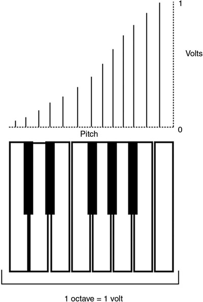
Figure 1.3 Visual representation of the 1volt/octave standard.
Although VCOs are coveted for their “warm” tonal quality, they oftentimes drift in and out of tune and are susceptible to temperature and environmental changes, making them quite finicky to use. For this reason, the digitally controlled oscillator was introduced.
Digitally Controlled Oscillator (DCO)
DCOs get their name because they are controlled digitally, typically through integrated circuit chips (ICs). Although forms of DCOs were present in some of the early monophonic analog synthesizers, it wasn’t until the introduction of polyphonic synthesizers like the Sequential Circuits Prophet 5 that DCOs really came into the spotlight. A polyphonic synthesizer is a synth that can play multiple notes at the same time. In hardware analog synthesizers, polyphony is achieved by having a separate synth voice for each note. Take the Prophet 5 for example, which has five voices of polyphony with each voice containing two oscillators, two envelope generators, a filter, and an amplifier.
At the time of the Prophet 5’s creation, having ten separate VCOs all staying in stable tuning while tracking the keyboard perfectly would have been an engineering nightmare and so it made more sense to use DCOs, which are far more stable. DCOs were used extensively through the eighties and early nineties and are still found on new synthesizers today. In fact, Van Halen’s iconic polyphonic synth sound on the song “Jump” would not have been possible had the Oberheim OBXa synthesizer not utilized digitally controlled oscillators.
Software-Based Oscillators
Software-based oscillators are typically found in software or VST (Virtual Studio Technology) synthesizers. There are a few hardware synthesizers such as the Arturia Origin and Access Virus line that also utilize software oscillators. As can be assumed, software-based oscillators use digital signal processing to produce tones. Most software oscillators are designed to emulate physical oscillators, but a few soft synths such as Logic’s Sculpture utilize the capabilities of software in order to create new and interesting sounds through instrument modeling.
Using Oscillators
Now that we have covered the technical details of oscillators and the waveforms they produce, we can explore how oscillators are used in the sound creation process. When creating a sound, the user combines the onboard oscillators in the mixer section in order to create huge, rich walls of sound or delicate, beautiful sounds, which will then be filtered and modulated. Although the way in which the user utilizes the oscillators is solely up to the user, many parameters are provided on oscillators in order to aid in the sound creation process.
Tune/Detune
Sound creation starts with the pitch of the individual oscillators. Each oscillator can be set perfectly in tune with the others in order to create what effectively sounds like one mega oscillator, or the user can slightly detune the oscillators from each other resulting in a thick phasing, animated sound. Changing the octave of one of the oscillators (usually referred to as “range”—measured in footage in reference to organ pipe lengths) will result in a sound so large, it will be the dominate sound in any mix. The user can also tune one of the oscillators up or down an increment like a third or a fifth in order to create harmonies.
Based on the information collected, 74% of subtractive synthesizers feature oscillator detune capabilities.
Oscillator Sync
By listening to the synth solo on Herbie Hancock’s “Chameleon,” one understands the sheer depth of what oscillator sync can add to a synth patch. When oscillator sync is engaged, the first oscillator retriggers the second oscillator’s wave when the first oscillator’s waveform falls back to zero. This feature allows the user to adjust the second oscillator’s pitch without getting the oscillators out of tune. The timbre of the sound will change depending on how the second oscillator is tuned, which creates extremely interesting sonic capabilities. Understanding and using oscillator sync is one of the things that separates the novice from the experienced. Oscillator sync is an essential tool in the synthesist’s sonic toolbox.
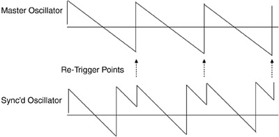
Figure 1.4 With oscillator sync engaged, the master oscillator retriggers the slave oscillator each time its wave cycle restarts.
Based on the information collected, 56% of subtractive synthesizers feature oscillator sync capabilities.
Sub-oscillator
Many synthesizers feature what is known as a sub-oscillator. A sub-oscillator clones the output of an oscillator and transposes it down one or two octaves. This allows the user to add an extra low end to a sound without using an entire oscillator to do so. A well-placed sub-oscillator thickens a synth patch to such a degree that once disengaged, it leaves users thinking their synths have become small and thin.
Based on the information collected, 28% of subtractive synthesizers feature sub-oscillators.
Noise
Noise is a crucial aspect of synthesis. Many synthesizers have an onboard noise circuit that produces white or pink noise. The user can mix the noise with the oscillators when creating drum sounds, or in order to add a pseudo-distortion to the sound that is unique from any type of distortion pedal.
Based on the information collected, 76% of subtractive synthesizers feature noise generation.
Spectral Shaping (Filtering)
When thinking about a subtractive synthesizer, be it an analog monster such as an ARP 2600 or a modern DSP based beauty such as the Roland Aria System 1, it is impossible to imagine not reaching for the cutoff frequency knob of the filter and rolling it back to produce that ever-amazing filter sweep. This has become one of the most instantly recognizable sounds in music, and, for some reason, it seems to sound good in almost any musical setting. If the oscillator is a synthesizer’s heart, then the filter is its diaphragm, lungs, and vocal chords—always breathing life into any patch, while giving the synthesizer a unique and distinguishable voice.
Bob Moog introduced the resonant low pass filter into his modular systems in the 1960s. Once he unveiled the 904a Transistor Ladder Filter, a paradigm shift took place, resulting in the landscape of synthesis that we know today. Every synthesizer company since Moog’s unveiling has included a resonant low pass filter into their designs. The very fact that the Moog 904a filter was the only module for which Moog filed a patent shows the importance of the resonant low pass filter. Although the low pass filter is by far the most common filter type found in synthesizers, there are others and it is worth examining the differences of each one.

Figure 1.5 The standard synthesis filter shapes.
Low Pass Filter
As stated earlier, the low pass filter is the most common type of filter when dealing with subtractive synthesis. A low pass filter works by “rolling off” or cutting all frequencies above a user-specified point known as the cutoff frequency. The rate at which the filter reduces the amplitude of these frequencies is called its slope and is measured in dB/octave. The classic Moog filter is a 24dB/octave filter, which means all frequencies above the cutoff frequency are attenuated by 24dB at every octave. Another classic filter slope is a 12dB/octave filter. With a 12dB/octave filter, all frequencies above the cutoff frequency are attenuated by 12dB at every octave. Often-times, the filter’s slope is labeled in “poles.” One pole loosely relates to a 6dB/octave attenuation. Therefore, a 12dB/octave filter is known as a two-pole filter and a 24dB/octave filter is known as a four-pole filter. Some synthesizers have the option to switch the filter’s slope in order to have more control over the end sound. Low pass filters are used to create the instantly recognizable filter sweep. Many synthesizers even allow external audio to be patched into the synthesizer’s filter in order to perform this filter sweep on drums, vocals, or the song as a whole. Daft Punk uses low pass filters in order to filter all the instruments of a song back right before a huge climax in a large number of their songs. An example of this type of filtering can be found on the intro of Daft Punk’s song “Around the World.” The low pass filter is truly an icon in subtractive synthesis and will remain an icon for the foreseeable future and beyond.
Based on the information collected, 97% of subtractive synthesizers feature a low pass filter shape.
High Pass Filter
The next most commonly found filter on a subtractive synthesizer is a high pass filter. A high pass filter (HPF) is the exact opposite of a low pass filter. In an HPF, all frequencies below the cutoff frequency are attenuated. HPFs are found alongside low pass filters on synthesizers and although not typically user selectable, high pass filters can have different slopes as well and follow the same dB/octave formula found on low pass filters. The Korg MS-20 synthesizer is famous for its filter section because it offers a resonant low pass alongside a resonant high pass filter. Extremely screeching leads can be produced when properly using a high pass filter. Although typically overlooked for bass patches, using a resonant high pass filter with just the slightest amount of filtering can produce one the largest synth bass sounds imaginable due to the resonant frequency being on the low end of the audio spectrum, but while still allowing all the bright, high-end sound to pass through. The Chemical Brothers are known to use the high pass filter of their MS-20s on most of their songs. An example of the screeching sounds only a high pass filter can provide can be found in the introduction of The Chemical Brother’s “We are the Night” track. The high passed MS-20 is the screeching modulated sound that is heard while the rest of the song is low passed in the background.
Based on the information collected, 53% of subtractive synthesizers feature a high pass filter shape.
Band Pass Filter
Another filter found on some subtractive synthesizers is known as a band pass filter. A band pass filter (BPF) is a combination of a high pass filter and a low pass filter. The band pass filter attenuates all frequencies above and below a set “band” of frequencies centered on the cutoff frequency. A band pass filter often has a fixed bandwidth, meaning the amount of frequencies around the cutoff frequency that won’t be attenuated is a fixed amount. Band pass filters are great for creating nasally thinner sounds such as oboes, saxophones, and other reed instruments.
Based on the information collected, 37% of subtractive synthesizers feature a band pass filter shape.
Band Reject or Notch Filter
The final filter type usually associated with subtractive synthesizers is known as a band reject or notch filter. A band reject filter is the exact opposite of a band pass filter in that the frequency band around the cutoff frequency is attenuated while leaving the frequencies on either side to remain unaffected. Although typically used in music production as a means to eliminate problem frequencies, the notch filter, when properly used on a synthesizer, can produce interesting sounds not otherwise attainable.
Based on the information collected, 24% of subtractive synthesizers feature a band reject or notch filter shape.
Using Filters
Like with anything on a synthesizer, the way in which the user utilizes the filter is completely up to the user. Most filters have predetermined parameters available to the user in order to aid in the sound-creation process. Let’s take a look at some of the commonly found parameters of a subtractive synthesizer’s filter in order to better understand what they do.
Cutoff Frequency
If you are only going to adjust one parameter on a synthesizer, chances are this is it. The cutoff frequency determines the frequency at which the filter will start working and it is this control that produces those infamous filter sweeps. The cutoff control is usually a prominent knob or slider in the filter section with easy access so that the user can manually adjust it in real time.

Figure 1.6 Cutoff frequency.
Resonance
Ever since Moog released the 904a transistor ladder filter in the 1960s, resonance, sometimes known as “peak” or “emphasis,” has been a nearly universal parameter on all synthesizer filters. Resonance is a feedback circuit that feeds the cutoff frequency back into the filter, causing that frequency to jump above the center line and boosting the cutoff frequency and the adjacent frequencies. As the user turns up the resonance knob, the filter begins to ring or “resonate” at the cutoff frequency. Some filters self-oscillate when turned up, producing a sine wave at the pitch of the cutoff frequency. When used in conjunction with the filter cutoff, resonance imparts an amazing, animated sound onto any synth patch. Resonance can be thought of as the secret ingredient that makes filters so amazing and memorable.
Based on the information collected, 94% of subtractive synthesizers feature resonant filters.
Filter Voltage Control
Like with analog oscillators, analog filters are controlled via control voltages. These voltages are used to set the cutoff frequency without the need for the user to manually adjust the cutoff frequency knob. By patching an LFO or other modulation source into a filter’s control voltage input, the user can be free to play more complex lines while the filter automatically sweeps.

Figure 1.7 Resonance creates a “bump” in the frequencies around the cutoff frequency.
Envelope Amount
The envelope amount control determines the depth at which an envelope generator affects the filter’s cutoff frequency. Although the way in which the envelope controls the filter is covered in depth later in the chapter, it is important to know that most filters allow the user to determine just how much an envelope controls the filter. Most filters even allow the user to decide the polarity of how the envelope controls the filter, meaning that the envelope can control the filter in a positive or negative manner. By using an envelope to control a filter, the user can set the exact way the filter opens and closes every time a key is struck. Although some lower-end analog synthesizers do not allow envelope control over the filter, it has become an almost universal feature on synthesizers today.
Based on the information collected, 88% of subtractive synthesizers feature an envelope amount control over the synthesizer’s filter.
Key Follow
Because analog filters are controlled via control voltage, the same controllers used to determine pitch on an oscillator can be used to determine the cutoff frequency of a filter. This means that the synthesizer’s keyboard that produces higher voltages the higher up one plays can control the filter, and so most filters offer a function called “key follow” or “keyboard control.” When engaged, this function increases the filter’s cutoff the higher one plays on the keyboard, causing higher notes to be brighter and lower notes to be darker. Since this is such a sought-after feature on analog synthesizers, most modern digital and software synthesizers offer this feature using digital control instead of voltage control. Key follow can be used in more extreme degrees as a way to have a bass-sounding filter response at the lower end of the keyboard while having a lead-sounding filter response at the higher end. When used more subtly, key follow will impart an ever-evolving filter response as one plays across a keyboard. One lesser-known way in which to use key follow is to crank the resonance to its highest degree, causing the filter to self-resonate; then, by tuning the cutoff frequency so the filter resonates at a specific note, the user can “play the filter,” meaning that the resulting sine wave will track up and down the keyboard and allow the user to have a fully functional sine wave generator.

Figure 1.8 Visual representation of key follow.
Based on the information collected, 77% of subtractive synthesizers feature key follow functionality.
Filter Selection
Rather than having individual filters for low pass, high pass, band pass, and band reject filter types, many synthesizers allow the user to switch filter types using the onboard filter, allowing the synthesizer to have one, all-encompassing filter. The Oberheim multimode filter found on their analog synths is usually credited as being the first successful, multimode filter. That being said, it is not uncommon to see a high pass filter in conjunction to the main multimode filter on many synthesizers.
Amplitude Shaping (Amplifiers and Envelope Generators)
In an analog oscillator circuit, sound is always present at the output stage whether a key is pressed or not. Because oscillators continuously produce a pitch, it is necessary to have a circuit that only lets sound out of the output when a key is pressed. The circuit responsible for releasing sound to the output or withholding sound when the user specifies is known as the amplifier. In an analog synthesizer, the amplifier is controlled via control voltage in the same vein as the filter and oscillators. The amplifier allows sound to pass when a positive voltage is present and refuses sound from passing when no voltage is present. This voltage is known as a gate signal and is typically made up of a +5v pulse wave. If synthesizers just produced sound the instance a key was depressed and immediately fell silent the instant the key was released, they would neither be very musical nor beneficial to most users. Therefore, it is necessary to be able to control the way in which the synthesizer’s sound begins, maintains, and falls. This type of sound control is achieved with what is known as an envelope generator.
Envelope Generators
When a pianist strikes a key on a piano, the sound does not maintain its full amplitude and energy throughout the duration of the key being depressed. Once a key is struck on a piano, the sound level quickly peaks and then falls and continues to fall slowly until it is inaudible. This type of sound characteristic is known in the synthesizer world as the instrument’s envelope. An envelope generator replaces a gate signal with a modified gate signal in which the user specifies the rate at which the sound peaks and falls.
The most common type of envelope generator found on synthesizers is known as an ADSR envelope. ADSR stands for attack, decay, sustain, and release. The user specifies the length of each of these parameters in order to create a desired envelope for the sound. Although many synthesizers offer full ADSR envelope generators, some offer variations such as an AR envelope, which would just have attack and release controls, or an ADR envelope which would just have attack, decay, and release controls. This is especially true when synthesizers feature more than one envelope generator, in which case, one will usually be an ADSR while the others might be a variation. Let’s take a look at each of these parameters in depth to better understand how they affect the overall sound of the synthesizer.

Figure 1.9 The standard ADSR envelope generator shape and its parameters.
Based on the information collected, subtractive synthesizers feature an average of three envelope generators.
Attack
The attack portion of an envelope generator controls the speed at which the sound is heard when a key is struck. A short attack yields a sound that is heard at the instant the key is depressed, while a slow attack yields a sound that slowly rises in amplitude from when the key is depressed. The rate at which the attack of an envelope can be adjusted is different from synthesizer to synthesizer, but is usually adjustable from a few milliseconds to a few seconds. By simply slowing down the attack, beautiful string sounds can be created that rise and build to their climax slowly. Slowing down the attack time is also great for making long, warm synth pad type patches.
Based on the information collected, 96% of subtractive synthesizers feature an envelope attack control.
Decay
The decay portion of an envelope generator specifies the amount of time it takes the sound to fall from its highest peak to its sustain point. Like the attack parameter, the decay control can typically be adjusted from a few milliseconds up to a few seconds. Decay can be thought of as the amount of time it takes the piano to fall to its sustaining sound once the transient sound of the string being struck has died down. Setting a long decay time will help create an ever-moving and evolving synth pad sound.
Based on the information collected, 93% of subtractive synthesizers feature an envelope decay control.
Sustain
The sustain parameter of an envelope generator determines the amplitude at which the sound remains while the key is depressed after its initial attack and decay times. Unlike the attack and decay parameters, the sustain parameter is not measured in time. Instead, a lower sustain results in a signal with a lower amplitude once it reaches its sustain point, while a greater sustain results in a sound with a greater amplitude. Many budget synthesizers unfortunately neglect to include a user-adjustable sustain parameter on their envelope generators, even though the sustain parameter is extremely important in sound creation. When setting an extremely low sustain with a short attack and decay, a synth can produce extremely short percussive sounds great for drum creation, chirping rhythms, or complex sequences. When cranking the sustain to its highest level, the amplitude will stay at its highest peak for the duration of the key being depressed, resulting in huge walls of sound sure to rock the foundation of any piece of music the sound is inserted into.
Based on the information collected, 91% of subtractive synthesizers feature an envelope sustain control.
Release
The final parameter found in an ADSR envelope is known as release. The release determines the amount of time it takes the sound to fall down to an inaudible level once the key is released. This is like the way that a piano still “rings out” even once the player releases a depressed key. Release time is another important parameter that is sometimes left out of budget synthesizers. The release parameter, when set to longer lengths, allows a user to have notes continue to sound until the next note is triggered, effectively mimicking the way a sustain pedal works on a piano when the pianist releases the pedal at the next note. When using the release parameter in this way, the user is free to move his or her hands up or down the keyboard in anticipation of the next phrase without the synthesizer abruptly going quiet when a key is released. Setting a long release not only aids in creating long, moving synth pads, but also helps create screaming synth solos.
Based on the information collected, 87% of subtractive synthesizers feature an envelope release control.
Envelope Control over Filters
An envelope generator is used for more than just controlling amplifiers. One common parameter that is controllable via an envelope is the filter. In fact, many synthesizers contain a second ADSR envelope generator designed specifically to control the filter. Having an envelope available to control the filter allows the user to program filter sweeps and evolving filter sounds without having to manually adjust the cutoff frequency. Although the envelope controls are the same when controlling a filter, the results each parameter has on the filter are different than with an amplifier, so it is important to examine the effect each parameter bestows when controlling a filter.
Filter Envelope Attack
When using an envelope generator to control a filter, the attack determines the amount of time it takes the filter to reach the cutoff frequency once a key is pressed. By adjusting the attack time, the user effectively creates a filter sweep up to the cutoff frequency when striking a key. With a bit of resonance and a slightly longer attack time, the filter opens shortly after the note sounds, creating an almost wet, bouncy type of sound that lends itself to bass patches beautifully. This type of sound is heard on Prince’s “Controversy” song. A long attack time slowly increases the cutoff frequency, allowing for extremely animated synth pad and lead sounds. Adjusting the attack time of a filter also aids in creating brassy sounds.
Filter Envelope Decay
When controlling a filter, the decay control determines the amount of time it takes the filter cutoff frequency to fall from its highest level right after the attack, to its set sustain point. This parameter allows the user to have a filter that sweeps down after a key is pressed; this allows it to pierce through a mix at the instant the note is heard and then fall back into the background while still being audible. Like with an amplifier envelope, the decay works in conjunction with the sustain parameter.
Filter Envelope Sustain
The sustain parameter in regards to the filter envelope determines a new cutoff frequency that the filter will remain at while a key is being depressed after the initial attack and decay times have run their course. By setting a low sustain with a long decay, the filter slowly closes while a key is being held, creating beautiful, evolving pads and lead sounds. A low sustain with a short decay yields extremely sharp and percussive sounds that, when mixed with resonance, are used to create slap bass or kick drum-like sounds.
Filter Envelope Release
The release control of a filter envelope determines the speed at which the filter closes once a key is released. Adjusting each parameter of a filter envelope generator allows the user to create ever-evolving filter responses that can sound either beautiful and musical or extremely crazy and exciting. By having an ADSR envelope for both the filter and the amplifier, the possibilities are endless on the sounds that can be created.
Envelope Control over Pitch
One final use for an envelope generator found on certain synthesizers is the ability to control pitch. A pitch envelope is used for creating sound effect-type sounds but it can also be quite musical. When using a pitch envelope, the attack control determines the speed at which the oscillator rises in pitch until it reaches the set pitch of the oscillator. The decay determines the speed at which the pitch will fall from the highest point to the user-set sustain pitch. The sustain control determines the frequency at which the oscillator will stay while a key is being depressed. And finally, the release control determines the time it takes the pitch to fall from the sustain pitch down to an inaudible range once a key is released. The ability to have so much control over every aspect of the sound is one of the main reasons synthesizers are able to create the sounds that they can.
A Note on Envelope Generators
It is important to understand that an envelope generator is the same exact circuit whether it’s controlling an amplifier, a filter, or an oscillator’s pitch—the only difference being the destination it is routed to. For example, when using a modular synthesizer, which uses patch cables to connect individual modules such as oscillators and filters together, the envelope generators one would use to control amps, filters, and oscillators would all be the exact same module. The number of destinations to which one could route an envelope in a modular system would be reliant on how many individual envelope generators were in the system. On a hardware, nonmodular synthesizer such as the MiniMoog, the synthesizer designer determines a fixed number of envelopes and destinations. In the case of the MiniMoog, there are two individual ADSR envelope generators with one permanently routed to the filter and one to the amplifier.
Modulation (LFOs and Sample and Hold)
An LFO, or low frequency oscillator, is an oscillator which produces frequencies below the audible range in order to control other aspects of the synthesizer. LFOs are the main source of modulation in a synthesizer, and like an envelope generator, the LFO can change the sound of various parameters on a synthesizer. In some synthesizers, LFOs can be used to trigger envelope generators in order to create precise repeating rhythms. LFOs are one of the most versatile features on a synthesizer because they can be used to add slight vibrato or tremolo onto a sound, or be used to create rhythmic mangling of a sound heard on the most intense of electronic music songs. The stereotypical “Dub-Step” wobble bass sounds are created using LFOs. Let’s examine just what an LFO is and what it does in order to better understand how it can be used.
LFOs vs. Oscillators
As stated above, an LFO is an oscillator that produces frequencies that are lower than the audible frequency range. It should be understood that an LFO circuit is virtually identical to an oscillator circuit, with the only difference being that the frequencies they produce are lower. In the MiniMoog for example, there is no stand-alone LFO; instead, the third oscillator can be switched into “LO” mode, which lowers the frequency range of oscillator three in order for it to be used as an LFO. Because LFOs are identical to oscillators, all the wave forms of a traditional oscillator can be utilized in an LFO. In order to keep costs down, many synthesizer companies limit the amount of waveforms their LFOs can produce. That being said, higher-end synthesizers usually have LFOs that can produce most if not all waveforms that their oscillators produce. Therefore let’s examine each of the standard synthesizer waveforms again, this time concentrating on what effect they will produce when used as an LFO.
Based on the information collected, subtractive synthesizers feature two LFOs on average.
LFO Sine Wave
A sine wave has gently rounded peaks and troughs, which correspond to the gentle rise and fall of the parameter being modulated at the speed of the LFO. The sine wave is often used to create vibrato and tremolo effects and is one of the most common LFO waveforms offered on both expensive and budget synthesizers. When used at their extreme, sine wave LFOs impart an intense wobble onto whatever parameter is being modulated.
Based on the information collected, 44% of subtractive synthesizers feature LFO sine wave generation.
LFO Triangle Wave
Next to the sine wave, the triangle wave is the second most common waveform found on LFOs. Similar to the sine wave, the triangle wave is used heavily for both vibrato and tremolo effects. Based off of the triangular wave shape, a triangle wave LFO imparts a sharper rise and fall onto the parameter being modulated, allowing for sharper vibrato in their more modest settings and harsher wobbles in their more extreme settings.
Based on the information collected, 80% of subtractive synthesizers feature LFO triangle wave generation.
LFO Sawtooth Wave
When used as a modulation source, the sawtooth wave imparts an immediate rise and then elongated fall onto the parameter being modulated. Sawtooth modulation sounds like rhythmic knife slices are being taken out of whatever they are modulating, and so sawtooth wave modulation is extremely effective when creating sound effects on a synthesizer.
Based on the information collected, 54% of subtractive synthesizers feature LFO sawtooth wave generation.
LFO Ramp Wave
The ramp wave is a reversed sawtooth wave and when used in oscillators, ramp and sawtooth waves are virtually indistinguishable. When used as a modulation source, however, ramp and sawtooth waves are very different. A ramp wave modulation imparts a rise and then instantaneous fall onto the parameter being modulated. Like sawtooth modulation, ramp wave modulation is extremely useful when creating sound effects on a synthesizer and effectively does whatever sawtooth modulation does, only reversed.
Based on the information collected, 40% of subtractive synthesizers feature LFO ramp wave generation.
LFO Pulse/Square Wave
Square wave modulation is often used to trigger envelope generators in a synthesizer. When used as a trigger source, a square wave LFO triggers the synthesizer to sound every time the wave cycle repeats. This means that instead of hitting a key on the keyboard repeatedly on every beat, the user can use an LFO to achieve this sound with exact timing and precision. Pulse/square wave modulation is not limited to envelope triggering, and a pulse/square wave can also be used to modulate any parameter that is available to be modulated. When used as a modulation source rather than a trigger source, a square/pulse wave imparts up/down modulation onto the parameter being modulated, producing anything from “glitchy,” stabbing sound effects to rhythmic, pulsating sounds.
Based on the information collected, 78% of subtractive synthesizers feature LFO pulse or square wave generation.
LFO Pitch Modulation
A common destination that can be modulated via an LFO is pitch. Pitch modulation works by routing the LFO output into the oscillator’s pitch control. When using pitch modulation, the pitch rises with the rising LFO waveform and falls with the falling LFO waveform. The amount that the LFO affects pitch can be determined with an LFO depth control, such as a knob or controller wheel. Pitch modulation creates a vibrato effect at lower depths and a harsh, frequency-modulated effect at higher depths. If oscillator sync is engaged and the LFO is set to modulate only the sync’d oscillator’s pitch, some of the most exciting sounds in synthesis can be created.
LFO Amplifier Modulation
When used to modulate the synthesizer’s amplifier, the LFO can be used to create a tremolo effect. When modulating an amplifier, the amplitude increases with the rise of the LFO’s waveform and decreases with the fall of the LFO’s waveform. At greater depths, the sound cuts in and out at the rate of the LFO. When the LFO’s frequency is increased to near audio rates, the synth gets an almost distorted quality to it that sounds truly amazing.
LFO Filter Modulation
Another common LFO destination is the filter. When engaged, the filter opens with the rise of the LFO’s wave and closes with the fall of the LFO’s waveform. This means that an LFO can be used to increase and decrease the cutoff frequency of the filter, creating pleasing, long filter sweeps or “Wah-Wah” type effects. When filter resonance is increased, filter modulation imparts an extremely pleasing animated sound to the filter at lower depths and extreme glitchy sounds at more extreme depths.
LFO Pulse Width Modulation
Pulse width modulation (PWM) is a staple in subtractive synthesis. To achieve pulse width modulation the LFO must be routed to the pulse width control of one or more of the oscillators. The width of the pulse wave changes with the rise and fall of the LFO’s waveform. Most higher-end synthesizers as well as budget synthesizers offer pulse width modulation due to its sonic qualities and high esteem held by users.
Based on the information collected, 74% of subtractive synthesizers feature pulse width modulation.
Sample and Hold
Although not exactly an LFO waveform, many LFOs feature sample and hold functionality. A sample and hold circuit takes voltage snap shots of a signal at its input stage and then applies them to a parameter of the synthesizer at a set rate. The most common signal typically fed into an LFO is white noise. Because white noise contains all frequencies, a sample and hold circuit takes a snapshot of a different frequency at every interval, resulting in a random sequence at the output stage. One way in which sample and hold is utilized is by feeding the output stage to an oscillator, causing random pitches to be produced at the rate of the sample and hold circuit. Another typical use of sample and hold is for the output stage to be routed to the filter, causing random cutoff frequencies to be produced. Arp was famous for its versatile sample and hold circuits on their synthesizers. When the late George Duke was Frank Zappa’s keyboardist, he used the sample and hold of his Arp Odyssey on many iconic Zappa songs. Pete Townshend used the sample and hold circuit in conjunction with a sequencer patched into the filter on his Arp 2500 to create the iconic opening sound on The Who song “Baba O’Riley.”
Figure 1.10 Visual representation of sample and hold.
Based on the information collected, 58% of subtractive synthesizers feature sample and hold capabilities.
Controlling a Synthesizer
In the early days of electronic music synthesizers, controlling pitch, especially the fixed pitches of a 12-tone Western scale, was troublesome. Many people were experimenting with different ways to produce set pitches. By far the most common type of synthesizer control is the keyboard (similar in look and function to a piano keyboard). Bob Moog is most often credited with introducing the traditional black and white keyboard into synthesis. At the same time that Moog was using keyboards to control his modular systems however, Don Buchla was experimenting with new and interesting ways to control his modular synthesizers in an effort to release the electronic musician from feeling trapped to tonal, Western music. The types of controllers that Buchla was designing included sequencers, push buttons, and metal touch plates. Although the right type of controller to use in order to control a synthesizer is solely up to the user and his or her wishes, the traditional keyboard is by far the most common.
Keyboards
Analog synthesizers are controlled via voltages known as C.V., and so analog synthesizer keyboards produce control voltages whether they are stand-alone keyboard controllers for modular synthesizers or built-in keyboards, such as is found on the Arp Odyssey or the Korg MS-20. Each key on an analog synthesizer typically produces two voltages, a 1/12-volt increment (or different volt/Hz/octave standard) for controlling pitch, and a +5v pulse for producing gates. On a stand-alone synth, such as the MiniMoog, the volt/octave voltage is internally routed to the oscillator for pitch, for filter, and for key follow, while the pulse voltage is internally routed to the envelope generators and amplifier. In many modern synthesizers, even modern analog synthesizers (such as the Arturia MiniBrute), the keyboard is connected to the oscillators and filters via MIDI. The keyboard is the most prominent pitch controller for synthesizers due to the ease in which users can play the synthesizer musically.

Figure 1.11 Traditional synthesizer keyboard as seen on the Sequential Circuits Pro-One synthesizer. Photo courtesy of www.switchedonaustin.com.
Sequencers
A sequencer is a device that produces note and gate information in order to control a synthesizer without the need for a user to physically play a keyboard. The most common type of sequencer is what is known as a step sequencer. An analog step sequencer usually has either 8, 16, or 24 steps that can each be programmed individually to produce a note in a given range (around three octaves). A step sequencer receives its clocking information from a gate pulse, either internally or from an external source. Step sequencers have the ability to place a mute on any of the steps to create complex patterns. Analog sequencers, both vintage and modern, produce control voltages, while modern digital sequencers typically produce MIDI notes. Because sequencers produce either control voltage or MIDI information, it is easy to integrate them into any synthesizer setup. Although early sequencers were stand-alone units or modules, many synthesizer companies began including them in their synths in the mid-1970s and still do today. Giorgio Moroder used sequencers extensively in his music, which in turn changed the course of electronic music and practically paved the way for modern dance music. Moroder’s ground-breaking sequences can be heard extensively in Donna Summer’s song “I Feel Love.”

Figure 1.12 Division 6 SQ18 Eurorack step sequencer.
Based on the information collected, 29% of subtractive synthesizers feature sequencers.
Arpeggiators
Like a step sequencer, an arpeggiator produces note and gate information in a step-like pattern. The main difference being that an arpeggiator gets its note information from keys being held down on a keyboard and reproduces these notes in a low-note-to-high-note order. Therefore, arpeggiators are far more limited in their ability to be programmed and are generally used as a means of live performance control rather than a stand-alone synthesizer controller. Arpeggiators get their name because they physically arpeggiate chords that are being held down on the synthesizer’s keyboard.
Based on the information collected, 28% of subtractive synthesizers feature arpeggiators.
Other Means of Synthesizer Control
As stated earlier, designers like Don Buchla were experimenting with various types of synthesizer controllers at the time of the traditional keyboard’s introduction to synthesis. These more esoteric controllers are very much still alive today and are available to artists who want to veer away from traditional, Western, tonal music. Modern Buchla synthesizers, for example, use touch plates that react to a variety of different factors, such as where a finger physically is on the plate, the amount of surface area a finger takes up, as well as pressure. Other controllers such as the Haken Continuum use ribbon technology, which allows a user to smoothly glide between notes by sliding his or her finger across the controller. Some synthesizers utilize a combination between esoteric control and traditional keyboard control. The EMS Synthi AKS, for example, used a touch plate printed to look like a traditional keyboard that responds to the 40Hz hum present in the human finger. The EDP Wasp synth used a similarly flat touch plate, but responds to heat rather than the 40Hz hum in the human finger. The amount of esoteric controllers on the market is vast and it would fill many chapters to detail each and every one.

Figure 1.13 Visual representation of an arpeggiator.
Performance Control
Most synthesizers offer various means of performance control. These controls are designed in order to give the user maximum control over the synthesizer in order to perform live or in the studio. Let’s examine some of the more common types of performance control on subtractive synthesizers.
Glide
Glide, sometimes referred to as portamento or glissando, allows the user to create a smooth slide between notes when playing on the keyboard. With glide engaged, the oscillators will rise in pitch, at a rate determined by the user, from the first note to the next when playing up the keyboard, and will fall in pitch from one note to another when playing down the keyboard. The glide function is similar to bending a guitar string from one note to another, meaning that one note slides in pitch to the next rather than just producing the first note and then producing the second. The glide time can usually be set between a few milliseconds up to a few seconds. Using the glide function while performing on a synthesizer imparts a musical attribute to the sound that, when applied correctly, can transform a synth line from being boring and stagnant to being exciting and moving. In more extreme cases, the user can set the glide time to extremely long lengths in order to create a sound that keeps slowly rising or falling in pitch as an effect.
Based on the information collected, 79% of subtractive synthesizers feature glide capabilities.
Pitch Wheel
Most synthesizers feature a way in which to “bend” the pitch of an oscillator up or down. Most often, this control is seen in the form of a wheel, but joysticks, levers, and knobs are not uncommon as well. Many synthesizer pitch wheels, joysticks, and levers are spring loaded; in this way, the user can quickly bend the pitch and let go of the controller so that the pitch will quickly return back to its starting pitch.

Figure 1.14 MiniMoog Voyager pitch wheel (left) and modulation wheel (right).
Based on the information collected, 60% of subtractive synthesizers feature pitch wheels.
Modulation Wheel
When using an LFO to modulate a certain parameter of a synthesizer, the user can set the depth of the modulation. Most synthesizers offer a wheel, joystick, or lever similar to the pitch control for setting the modulation depth. Unlike the pitch control, however, a modulation wheel is typically not spring loaded, so the user can increase the depth and leave it for as long as desired.
Based on the information collected, 52% of subtractive synthesizers feature modulation wheels.
Ribbon Controllers
Although not nearly as common as wheels, joysticks, and levers, ribbon controllers are found on certain synthesizers. A ribbon controller works by sliding a finger across its flat surface. A ribbon controller can usually be set to control a variety of parameters on a synthesizer, but pitch, filter, and modulation depth are the most common destinations for the ribbon controller to affect.
It is because of this vast amount of user-controllable features that subtractive synthesis has survived throughout the decades since its introduction. By learning what each parameter does and how it affects the sound, the user creates a physical connection between them and the instrument, which imparts a sentimental quality to the music that is produced. People have long coveted their synthesizers and held them in the highest regards like a classically trained violinist cherishes their violin. Music would not be where it is today had the electronic music synthesizer not come onto the scene and produced a paradigm shift in which the entire music landscape was altered.
Recipes
The following ten recipes have been handcrafted by us and are designed to help teach some of the theories and techniques mentioned in this chapter. For the beginner, these patches will provide you not only with an eclectic set of patches, but will also help instill some fundamental synthesis knowledge by physically re-creating these patches. For the experienced, these patches can be a jumping-off point as well as a source of inspiration for creating your own patches. Either way, these patches are designed to sound good, represent and feature various functions of a subtractive synthesizer, and provide you with some fun synth explorations.
Recipe 1: Punchy Bass
This first recipe is designed as a synth-heavy bass patch. The patch features a quick filter envelope, which causes the filter to close rapidly and only allowing for a small fragment of full, harmonic content. With added resonance, this filter envelope setting really makes the sound become animated. This patch is well suited for really any type of genre that requires a super synth bass.
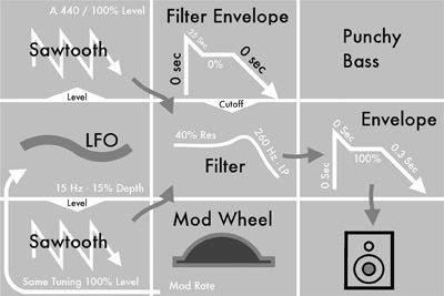
Figure 1.15 Recipe 1—Punchy Bass.
When re-creating this patch, the two oscillators will be set to sawtooth and square waves respectively. The two oscillators should be set perfectly in tune with one another. If desired, the two oscillators can be slightly off tune with one another by a few cents to thicken up the sound. This patch was designed as a bass patch so the oscillators should be set to 32’ or 16’ ranges. The low pass filter’s cutoff should be set at 260 Hz in order to roll off much of the high-frequency content of the sound. Resonance should be set to around 40%, but this can be tuned to taste depending on your particular filter. This patch requires two separate envelope generators with one routed to control the amplifier and one routed to control the filter. Starting with the filter envelope, the attack control should be set to zero seconds, or as short as it can go. The decay parameter should be quite short, around 0.25 seconds. The sustain should be all the way down at 0% and the release should also be turned all the way down. By having such a short decay time with no sustain, the filter will be open right as a key is pressed, and then it will quickly close, resulting in a quick filter sweep that plays on the resonance setting with each key press. Moving onto the amplifier envelope, the attack and decay parameters should be set to zero seconds, while the sustain should be set to 100%. Finally, the release should be set to around 0.3 seconds. By having the sustain set to 100%, the amplifier will stay at its max amplitude for the duration of a key being depressed. The release is set slightly longer in order to ensure no pops will be heard when a key is released. This patch was designed without any glide, but a short glide time could be added to add a bit of an extra flair. An LFO routed to the oscillators pitch and controlled via a mod wheel should be set to about 15Hz with around 15% depth to add vibrato when desired.
If a bit more punch is desired, a bit of white or pink noise could be added at a low level. Because of the shape of the filter envelope, most of the high frequency of any added noise will be cut out quickly, resulting in a nice, low-end oomph at each key press. Additionally, a third oscillator producing a sine or triangle wave could be added at an octave higher than the first two oscillators in order to add some extra beef to the sound.
Recipe 2: Evolving Lead
The second patch in our list is a slightly different take on a traditional lead patch. The filter will slowly open once a key is pressed, revealing more high frequency content as the sound progresses while a heavy dose of resonance will animate the sound and help it pierce through any mix. This patch was designed to fit greatly in an ambient or alternative setting, but will bode well in any R&B or even EDM track. This patch is extremely versatile; by simply adjusting the filter envelope’s attack, the sound can take on whole new life.
When re-creating this patch, the two oscillators will be set to produce sawtooth waves. One of the oscillators will be tuned an octave below the other to create a rich tone. The low pass filter cutoff is set relatively low at around 236Hz, while the resonance is set extremely high at around 85%. The filter envelope’s attack is set quite long at 2.5 seconds, while its decay is set longer—still at around three seconds. Sustain is set at 35%, while the release is set all the way up. This type of envelope shape will result in a filter that slowly opens once a key is pressed, and then slowly dies down to a more subdued state until it slowly closes once a key is released. This type of filter envelope shape lends itself well to a lead line that is played slowly while notes are held out. Unlike the filter envelope, the amplifier envelope shape is fairly basic with attack and decay set as short as they can go and sustain and release set to full. Glide is set to about 20%, but can be fine-tuned to taste. Finally, a vibrato LFO is set up at around 10Hz with about 20% depth.
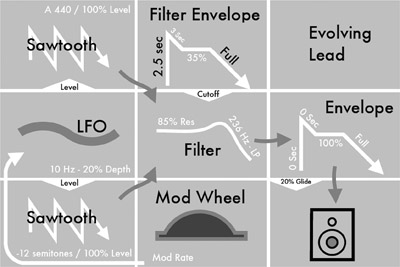
Figure 1.16 Recipe 2—Evolving Lead.
As was said above, simply adjusting the attack parameter of the filter envelope will result in drastically different sounds. In addition to this, adjusting the decay and sustain parameters of the filter envelope will adjust how the sound initially fades and remains while a key is being depressed. Changing the LFO to affect the filter cutoff will also allow for some cool, wah-wah-type effect.
Recipe 3: Effected, Evolving Pad
This patch is designed to be an out-of-the-ordinary pad sound. Being a pad, it is helpful to have some amount of polyphony available, but the patch sounds good monophonic as well. Due to a relatively fast LFO-controlling filter cutoff, the pad has a type or bubbly sound that makes it quite interesting. This type of pad would lend itself to most genres, but is mainly designed for an alternative pop genre.

Figure 1.17 Recipe 3—Effected, Evolving Pad.
When re-creating this patch, the two oscillators are set to produce sawtooth and square waves respectively. The square wave oscillator is tuned to minus seven semitones from the sawtooth oscillator. The low pass filter’s cutoff is set to 472Hz, while the resonance is almost fully engaged at 92%. The filter envelope’s attack time is set extremely long at nine seconds, while the decay is set to 2.5 seconds. The sustain level is semi-low at 35% and the release is turned to full. This envelope shape allows for an extremely long filter evolution that will work hand in hand with the LFO. The amplifier envelope is fairly basic with attack and decay set to zero and the sustain set to 100%. The amplifier envelope’s release is set to full. A fairly strong glide is set at 28%. Finally, a sine wave LFO is set fairly fast at 35Hz and is routed to the filter. The LFO in this patch is designed to constantly be engaged rather than controlled via a mod wheel. A 50% depth on the LFO is what was imagined for this patch, but it can be more or less based on your own personal preferences.
If desired, a third oscillator can be added either in tune with one of the others, or at another interval for a fuller sound. It is highly recommended that either pink or white noise is added at a low level to add some extra texture to the sound.
Recipe 4: Funk Lead
This Funk Lead patch is a fun lead sound that also works well as a rhythm or melody sound. The patch contains a chord-like sound with a tight, percussive filter envelope. Both the cutoff frequency of the filter and the resonance are set quite high resulting in an extremely bright sound. This patch will easily fit in a funk song, but will lend itself to any genre with a pop influence.
When re-creating this patch, the two oscillators are set to produce sawtooth waves with the second oscillator tuned up five semitones from the first. Both oscillators should be in a mid-to-high range, so 8’ or 4’ ranges are recommended. The low pass filter cutoff is set to 7200Hz with resonance at 80–100% (just under the point of self-oscillation). The filter envelope’s attack time is set to zero while the decay time is set to 0.1 seconds. The sustain and release controls are both set as low as they go. This envelope shape will create an animated percussive sound that bodes well for the rhythmic aspects needed for fun music. The amplifier envelope is a basic “on” shape with attack, decay, and release set to zero while sustain is set at 100%. A slight glide is set at 10%, and a relatively quick LFO, set to 18Hz, is routed to the oscillators pitch and is controlled via modulation wheel.

Figure 1.18 Recipe 4—Funk Lead.
If a thicker sound is desired, a third oscillator producing a square wave and tuned to the first oscillator can be added. White or pink noise can be added in a small amount to add extra punch to the sound. If you find that the envelope is too percussive for your taste, increasing the filter envelope’s decay time to around two seconds should suffice.
Recipe 5: Thick Bass
This bass patch differs from the first bass patch in that more emphasis is put onto the sound’s “oomph.” This bass patch is extremely thick and will be sure to rumble any subwoofer. As this is a fairly straightforward synth bass sound, it will fit nicely in any genre of music.

Figure 1.19 Recipe 5—Thick Bass.
When re-creating this patch, one oscillator is set to a sawtooth wave, while the second is set to a square wave that is an octave lower than the sawtooth. Since this is a bass patch, a low range should be set with the first oscillator at 16’ and second oscillator at 32’. The lowpass filter cutoff should be set to 170Hz with resonance set fairly high at 65%. Both the filter envelope’s attack and decay times are set to 0.5 seconds while the release is set to 0.4 seconds. Finally, the sustain is set to 0%. The amplifier envelope features the same “on” setting found in some of the previous patches with attack and decay set to zero and sustain set to 100%. The amplifier envelope’s release, however, is set to 0.4 seconds. The glide should be set at around 8% and finally a 15Hz LFO should be routed to the oscillators’ pitch for vibrato when engaged by the modulation wheel.
A third oscillator set to sine or triangle in the range of the first oscillator can be added for extra low end. Likewise, white or pink noise can be added to add extra grit to the sound.
Recipe 6: Percussive Staccato Pad
The sixth patch in our list is sort of unique in that it is designed to be a pad-like sound played on a monophonic synthesizer. That being said, this patch will also sound great on a polyphonic synthesizer, it’s just designed in such a way to make the most out of a monophonic synthesizer. The way the two envelopes are set up allows for a short, percussive sound, which then fades into a held-out, dark sound. This patch is not geared toward any type of genre and will lend itself well to any musical setting.

Figure 1.20 Recipe 6—Percussive Staccato Pad.
When re-creating this patch, the two oscillators are set to sawtooth and square with the square oscillator tuned down a full octave from the sawtooth oscillator. The low pass filter’s cutoff is set to 220Hz, while resonance is fully cranked to 100%. The resonance can be toned down a bit if you do not like the self-oscillation sound present from full resonance. The filter envelope’s attack is set to zero seconds, while the decay is set to about half a second. The sustain is left at 60% and, finally, the release is turned fully down to zero seconds. This envelope shape will yield a percussive sound that does not leave the filter fully closed. The amplifier envelope’s attack and decay times should both be set to zero seconds as well. Both the sustain and release parameters are turned fully up. With such a short filter envelope and long amplifier envelope, the sound will be piercing and bright at its onset and then quickly become dark and ring out for a long time.
This patch was designed with no glide, but it can certainly be added. The LFO should also be tuned to taste. Another idea is a slow filter LFO that can move the filter open and closed while the sound is ringing out. If you want a weirder sound, a fast LFO around 35 or 40Hz controlling the filter could be added in via modulation wheel.
Recipe 7: 60s Organ
Although this patch is named 60s Organ, it is not meant to be a patch that faithfully emulates any type of organ. Instead, this patch gets its inspiration from 60s organs such as the Vox Continental.
When re-creating this patch, both oscillators are set to triangle waves with the second oscillator tuned an octave below the first. Pink or white noise should be added in a small amount in order to mimic the noise present in these old organs. The low pass filter’s cutoff is set at 2800Hz with full resonance. The filter envelope’s attack and release times are set to zero seconds while the decay is set at 0.16 seconds. Finally, the sustain is set at 34%. The amplifier envelope’s attack and decay should both be set to zero seconds, while the sustain is set at 100%. Finally the release should be set around 0.17 seconds. No glide is required for this patch. If available, a 1Hz LFO should be routed to the amplifier in order to generate a slow, tremolo effect. If your LFO cannot be routed to your synthesizer’s amplifier, routing the same 1Hz LFO to the filter’s cutoff frequency is a good alternative.

Figure 1.21 Recipe 7—60s Organ.
This is a fun patch that can lend itself to any genre. Alternative or pop is most recommended, but it will fit nicely into any mix. The patch was designed with a polyphonic synthesizer in mind, but melodies and lead lines can be well executed on a monophonic synthesizer with this patch.
Recipe 8: Slow, Effected Lead
The eighth patch in this list is another take on a lead sound that is different from the stereotypical lead sounds out there. This patch contains an evolving filter with high resonance, which creates an effected sound that would be a nice addition to any piece of music.
When re-creating this patch, the two oscillators are set to square and sawtooth respectively, with the sawtooth oscillator tuned an octave above the square oscillator. The low pass filter’s cutoff is set to 90Hz while, the resonance is cranked as high as it will go. The filter envelope’s attack and decay are both set to zero seconds, while the sustain and release are both set to 100%. Both the amplifier envelope’s attack and decay parameters are set to zero seconds, while the sustain and release are set to 100%. Glide is added at 30%. A 0.6Hz sine wave LFO is routed to the filter cutoff with 100% depth to slowly open and close the filter as you play.
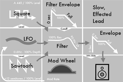
Figure 1.22 Recipe 8—Slow, Effected Lead.
An additional oscillator set to either sawtooth or square would be a good addition if you wish to beef up the sound. If your synthesizer has the capability of oscillator sync, engaging it on either oscillator would allow you to add some interesting harmonics to the sound.
Recipe 9: Chorded Trumpet
The ninth patch in our list draws its inspiration from a trumpet section, but is obviously designed so that it sounds more like a Roland Jupiter or Juno horn sound. The patch features two oscillators tuned at an interval in order to create a chord like sound.
When re-creating this patch, both oscillators are set to sawtooth waves with the second oscillator tuned up seven semitones from the first oscillator. The low pass filter’s cutoff is set to 156Hz with the resonance at 64%. The filter envelope’s attack time is set to 5.5 seconds, while its decay is set to 1.7 seconds. The sustain is set at 18% and the release is set at 0.05 seconds. The amplifier envelope’s attack and decay are both set at zero seconds, while the sustain is turned up to 100%. Finally, the amplifier envelope’s release is set at one second. No glide or noise is present in this patch, but can certainly be added if desired. The LFO is set fairly standard at around 15Hz and routed to pitch for a vibrato effect.

Figure 1.23 Recipe 9—Chorded Trumpet.
Recipe 10: Wall of Sound
The final patch in our list is a great patch that can really thicken up an entire mix. The sound is massive and can be thought of in the same light as a huge power chord played on a guitar. This particular patch is perfect for industrial, hard rock, metal, or EDM music.
When re-creating this patch, both oscillators are set to square waves with the second oscillator tuned a full octave below the first. The low pass filter’s cutoff is set at 2600Hz with resonance turned up to 65%. The filter envelope’s attack is set to zero seconds with the decay at 0.25 seconds. The sustain is set at 20%, while the release is set to 0.38 seconds. The amplifier envelope’s attack and decay times are both set to zero seconds, while its sustain is set at a full 100%. Finally, the amplifier envelope’s release time is set identical to the filter envelopes release time at 0.38 seconds. Glide is set to 20% and a 15Hz LFO can be routed to either the filter cutoff or pitch.
A third oscillator set to a sawtooth wave and tuned identically to the second oscillator so that it’s a full octave below the first oscillator is a great addition to this sound. Additionally, white or pink noise can be added in order to introduce more grit to the sound.
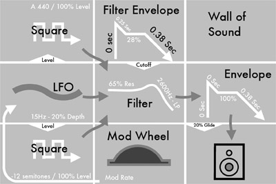
Figure 1.24 Recipe 10—Wall of Sound.
Historical Perspective on Subtractive Synthesis
Subtractive synthesis can be traced back to the dawn of the electric age. The first leaps forward in electronic musical instruments often happened by accident when inventors were experimenting with electricity. One of the first instances of electronic tone generation came in the form of the oscillating light arc invented by Elihu Thomson in the late 1800s. Although not intended as an electronic tone generator, Thomson found that his light arc would hum when operated.1 William Duddell, another early inventor, took Thomson’s design a bit further by wiring many oscillating light arcs together in order to perform “God Save the Queen.”2 Duddell’s performance on the oscillating light arc is often considered to be the first performance of an electronic instrument. In essence, what Thomson, and later Duddell, invented was the world’s first oscillator.
Early Electronic Instruments
Not long after the oscillating light arc, inventors such as Thaddeus Cahill and Leon Theremin began inventing electronic devices designed to play music. Cahill’s Teleharmonium and Theremin’s Etherphone (later named Theremin) were among the first electronic instruments ever designed.3 The Theremin went on to achieve success influencing future electronic music inventors. The Theremin, which is still in production today by numerous companies, is a noncontact, electro-harmonic instrument. The Theremin features two antennas (one for pitch, one for volume) that the user places his or her hands between in order to control the instrument. Two internal oscillators then produce one continuous wide range pitch via beat frequencies.4 The Theremin was widely used in virtuoso performances as well as a wide array of early science fiction movies.

Figure 1.25 A modern Moog Theremin; a direct ancestor to the original Theremin. Photo courtesy of www.switchedonaustin.com.
Soon after the Theremin’s debut, a French inventor by the name of Maurice Martenot released a similar sounding instrument known as the Ondes Martenot.5 The Ondes Martenot utilized a similar principle as the Theremin, but a keyboard and suspended ring was used as a means of control rather than antennas. Users would place their finger in a small, suspended ring underneath the keyboard and move their hand up and down the length of the keyboard in order to control pitch in a continuous manner.6 Due to the fact that a keyboard was available to be used as a reference, users could create stable pitches much easier with the Ondes Martenot than with the Theremin. Finally, the Ondes Martenot featured a physical block that the user would depress in order to change the amplitude of the instrument.
In the late 1930s, a new electronic musical instrument, designed by John M. Hanert, Laurens Hammond, and C. N. Williams, would be introduced that would revolutionize electronic instruments. This instrument was known as the Hammond Novachord. Not only was the Hammond Novachord able to electronically generate tones, it was able to do so with full polyphony, meaning that each key on the keyboard could be played simultaneously. Full polyphony was so revolutionary that it wouldn’t be commonplace on synthesizers until the late 1970s and 1980s. The Novachord was also revolutionary in the fact that it is considered to be the first synthesizer to utilize envelope generators.7
Soon after the Hammond Novachord was released, a new synthesizer called the Ondioline made its debut. The Ondioline, invented by Georges Jenny in 1941, was unique in that not only did it offer envelope generator control and a complex filter bank, it was one of the first synthesizers to feature a wealth of adjustable parameters that could easily be recalled, resulting in the first successful synthesizer to utilize a primitive form of preset control.8 Thanks to its complex filter bank and advanced envelope contours, the Ondioline was especially good at re-creating various orchestral sounds like oboes and violins.
As early electronic instruments like the Theremin, Ondes Martenot, and Odioline began to make an impression on the music industry, many influential people were taking notice. Two such people, Herbert Belar and Harry Olson, who were working for RCA, began work on their own electronic musical instrument. The instruments Olson and Belar would create would end up being known as the first fully programmable synthesizers—the RCA Electronic Sound Synthesizer MK I & II. The RCA synthesizers featured 12 and 24 oscillators respectively as well as a wide array of envelope and filter control. Perhaps what was most revolutionary about the RCA synthesizers was that they were fully controllable via an early binary computer that acted as a sequencer. The user would program the synthesizer by not only adjusting the machine itself, but by creating a sequence on perforated paper that would then be fed into the binary computer, effectively allowing the synthesizer to play itself. Although the RCA synthesizers were never produced commercially, they have gone down in history as the direct ancestors of the synthesizers we know and cherish today.
Moog and Buchla Modular Systems
In the early 1960s, two synthesizers would emerge from separate ends of the country almost simultaneously that would change the face of synthesis forever. These instruments were the Buchla 100 Series Modular Electronic Music System and the R. A. Moog Modular System. Many heated arguments have arisen as to whether Moog or Buchla created the first voltage controlled analog subtractive modular synthesizer. It is hard to determine who in fact was first, since they both emerged around the same year—1964. It is undeniable that the Moog went on to have more success, but the Buchla introduced things to synthesis that are still utilized today.
Dr. Robert Moog got his start in electronic musical instruments by building Theremin kits. Moog’s love for the Theremin not only got him interested in electronic musical instruments, but would introduce him to early electronic musician Herb Deutsch. Deutsch began to work with Moog on creating an electronic instrument that was desperately wanted by electronic musicians. Moog began creating a series of voltage controlled modules that each provided a different, sound-modifying function. Quickly thereafter, Moog began placing each of these modules in a wooden enclosure and selling them to the public. The modules Moog created varied from oscillators and LFOs, to envelope generators, attenuators, and amplifiers, and to filters and mixers. The modules would then be physically connected together via quarter-inch patch cables in order to build a desired sound. Moog is often credited with introducing the traditional keyboard as a means of designating pitch. Although using a keyboard to control a synthesizer was controversial among early, electronic music pioneers such as Morton Subotnick and Vladimir Ussachevsky, the idea caught on and has become the standard means of control among synthesizers.9
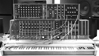
Figure 1.26 The first Moog modular system commercially produced. The instrument is part of the Stearns collection at the University of Michigan.
While Moog and Deutsch were creating what would become the Moog Modular in New York, Don Buchla was working on a modular synthesizer of his own near San Francisco, California. Buchla was approached by Morton Subotnick, along with a variety of other experimental electronic music artists working out of the San Francisco Tape Music Center, in order to build an electronic musical instrument. Subotnick made very clear that he did not want the synthesizer to be controlled via a traditional keyboard as he thought it would trap him into making tonal music, something he did not want to do. A few months later, Buchla arrived at the San Francisco Tape Music Center with a prototype of his modular system. Unlike the Moog, the Buchla synthesizer utilized a combination of touch plates and sequencers in order to designate pitch. In fact, the Buchla sequencer proved so successful, Moog ended up producing a similar sequencer for his modular system years later. Buchla’s approach to synthesis was quite different than Moog’s, and the term West Coast and East Coast synthesis has been coined for Buchla and Moog’s synths respectively.10

Figure 1.27 A 1969/70 Buchla 100 Series manufactured by CBS Musical Instruments. Image courtesy of Rick Smith with www.electricmusicbox.com.
As stated above, the Moog went on to monumental success and began showing up in a number of studios and musician’s homes despite the enormous cost. One such adopter of the Moog modular—Walter (now Wendy) Carlos—created an album featuring reworkings of famous Bach pieces on the synthesizer. This album, “Switched on Bach,” is responsible for bringing the synthesizer out of the experimental music studios and into popular culture.11
Analog Mono Synths of the 1970s
With the success of the Moog modular, synthesizers started to become a hot commodity. Due to the high cost and steep learning curve, though, many musicians were begging for something smaller, cheaper, and easier to use. Answering their call, Moog released the MiniMoog in 1974. The MiniMoog was a compact, road-ready synthesizer and keyboard combo that was internally wired, which negated the necessity of using patch cables to produce sound. For the first time, the synthesizer became something practically anybody could learn and was small enough to be brought on tour. The MiniMoog revolutionized synthesis and, soon, a wealth of companies began releasing compact analog synthesizers. ARP, Yamaha, Korg, Roland, EMS, Crumar, EML, Oberheim, and Sequential circuits were among the vast number of companies that produced analog mono synths that would create a paradigm shift in the music industry.
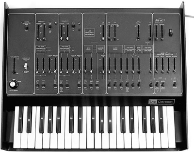
Figure 1.28 Arp Odyssey. Photo courtesy of www.switchedonaustin.com.
The Digital Age and Beyond
As analog subtractive synthesizers became commonplace amongst musicians, companies began producing digital synthesizers at a lower cost. Musicians began flocking to these new digital synthesizers due to their low cost, the fact they stayed reliably in tune, and because they featured presets making large, time-consuming tweaking unnecessary. As more and more musicians began selling off their old analog subtractive synthesizers for more complex digital synths, subtractive synthesis seemed all but doomed. The mid 1990s, however, brought with it a small resurgence of analog interest. At first, this new appreciation for analog subtractive synthesizers seemed to only have a cult following, but it was soon determined that users wanted new, subtractive synthesizers. Companies began producing software emulations of old analog gear as well as a number of digital subtractive synthesizers. As demand grew, companies like Moog and Dave Smith of Sequential Circuits began producing all-new analog subtractive synthesizers. In an almost ironic turn of fate, the synthesizer market was once again being flooded with not only analog subtractive synthesizers, but with modular analog synthesizers as well. The synthesizer industry has effectively come a full 360 degrees from where it started, and suffice it say, it is an exciting time for synthesis.

Figure 1.29 The Korg Little-Bits synthesizer system is a modular DIY analog synthesizer, which gives users an insight into the electronics and mechanics present in analog synthesizers.
Notes
1.Mary Jenkins, Analog Synthesizers, Focal Press, 2007, p. 20.
2.Jenkins, p. 63.
3.Jenkins, p. 24.
4.Vasilyey Yurii, “History and Design of Russian Electro-musical Instrument ‘Theremin.’ ” Paper presented at the annual Audio Engineering Society Convention. May 20–23, 2006, Paris, France.
5.Jenkins, p. 31.
6.“Ondes Martenot,” Encyclopedia Britannica. Retrieved from http://www.britannica.com/EBchecked/topic/428993/ondes-martenot
7.Michael Murphy and Eric Kupp, “An Examination of Early Analog and Digital Sampling—The Robb Wave Organ Circa 1927.” Paper presented at the annual Audio Engineering Society Convention. May 4–7, 2013, Rome, Italy.
8.Carlton Garner, “Electronic Instrument,” Encyclopedia Britannica. Retrieved from www.britannica.com/EBchecked/topic/183802/electronic-instrument/53835/The-tape-recorder-as-a-musical-tool#ref111938
9.Moog, DVD. Directed by Hans Fjellestad, 2004.
10.I Dream of Wires, Blu-Ray. Directed by Robert Fantinatto, 2013.
11.Robert A. Moog, “Electronic Music,” Journal of the Audio Engineering Society vol. 25, no. 10/11 (November 1, 1997), pp. 855–861.