
4 Microphones
Part 2
Electrostatic microphones
Figure 4.9 shows a typical, if simplified, circuit for an electrostatic microphone.
The capacitor part, known as the capsule, consists of the conductive diaphragm and the backplate. A d.c. supply, which is usually in the region of 50–100 V, provides a polarizing voltage on the capacitor. The charge on a capacitor is given by
Q = CV
where Q is the charge (in coulombs), C is the capacitance in farads and V is the voltage across the capacitor. The resistance R in the diagram is of extremely high value, a few hundred megohms, so that when the microphone is ‘switched on’ it takes an appreciable time (compared with the duration of sound wave cycles) for the capacitor to become fully charged. In short, the charge Q is, as it were, locked in. Consequently, if C varies, as it will do when the diaphragm vibrates, because Q is constant (it is determined by the area and spacing of the diaphragm and backplate), it follows that V, the voltage, must vary. It is this variation in voltage which constitutes the microphone's output.
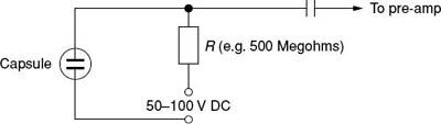
Figure 4.9 Basic circuit of an electrostatic microphone
The electrical impedance of the arrangement is very high and this means that the cable from the microphone to any other equipment will be seriously liable to pick up external interference – a 50 Hz hum from the mains being a common problem. For that reason a small amplifier – the pre-amp as it is often termed – has to be installed close to the capsule. There is now a new problem – providing power for this amplifier. Many microphones incorporate small batteries, but there are other ways of supplying power and these will be dealt with later in this section (‘Phantom power’).
Electret microphones, now very common, use special materials which carry a permanent electric charge on either the backplate or the diaphragm. Hence the term ‘electret’, by analogy with ‘magnet’. The use of these materials removes the need for a d.c. polarizing voltage across the capsule. A pre-amp is still needed, though, and this means a power supply of some sort, albeit no more than a small battery. Costly electret microphones are capable of extremely high quality, but it is also possible to buy quite inexpensive ones with respectable performances.
There is a further kind of electrostatic microphone – the r.f. electrostatic microphone (r.f. = radio frequency). The mode of working is too complicated to go into here and it must be enough to say that the capsule is used to vary the tuning of a radio frequency circuit – hence the name. They are expensive devices but they have the great advantage of being largely unaffected by humidity. Some types of gun microphone are of the r.f. variety and these are much used by broadcasters for outdoor work, where humidity might otherwise be a problem.
Production of the different polar responses
1. Omnidirectional
Perhaps paradoxically, sound waves must be allowed to reach only the front of the diaphragm. Diffraction (see Chapter 1) is relied upon to let sounds arriving off the main axis bend round and strike the diaphragm. At high frequencies, as we have said, this effect may not occur, or only partially. In some situations the failure to have a perfectly omnidirectional response at the higher frequencies may not matter.
Omnidirectional microphones are also termed pressure operated microphones, as it is the sound wave pressure and not some derivative of it that actuates the diaphragm. This point may be clearer after reading the next two sections on figure-of-eight and cardioid microphones.
2. Figure-of-eight
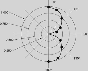
Both sides of the diaphragm are exposed to sound and what causes it to move is a force based on the pressure gradient – in other words the difference in acoustic pressures on the two sides. This means that the 0° and 180° angles of incidence give equal microphone outputs. Sounds arriving at angles of 90° or 270° will produce the same pressures on both sides of the diaphragm and thus will have no resultant force acting on it and it will not move: hence the lack of output for these angles of incidence. In mathematical terms the equation for a figure-of-eight pattern is given by
r = cos θ
where r represents the sensitivity at angle θ.
Here are some of the cosines of angles that can be found from a calculator:
Angle (degrees) |
Cosine |
0 |
1.000 |
20 |
0.940 |
40 |
0.766 |
60 |
0.500 |
75 |
0.259 |
90 |
0.000 |
120 |
–0.500 |
135 |
–0.707 |
160 |
–0.940 |
180 |
–1.000 |
Now, if these cosine values are plotted out on polar graph paper, as in the simplified version below, it can be seen that we can get a figure of eight pattern.
Two important practical points about this type of polar response may be mentioned here:
1. All microphones of this type show a phenomenon known as the proximity effect, sometimes called bass tip-up. This means that their bass output is increased when the source of sound waves is close to the microphone. The amount of this effect may vary with different microphones but speech typically begins to sound ‘bassy’ when the speaker is closer than 30–50 cm.
Bass tip-up is actually used to good effect in one type of commentator's microphone called a ‘lip ribbon’ microphone. Held close to the mouth, the bass tip-up would be excessive if it weren't compensated for by a bass-cut system. In cutting down the unwanted bass from a close sound, distant bass sounds (crowd noises at a football match, for instance) are greatly reduced.
2. Another and undesirable effect is that these microphones are rumble-prone – any movement of the microphone is likely to result in excessive rumbling noises in the output.
These microphones are also extremely sensitive to air movements such as wind.
3. Cardioids
Mathematically a cardioid pattern may be represented by
r = 1 + cos θ.
Notice that this is the equation for a figure-of-eight with the addition of a constant, namely 1. In acoustic terms this means combining a figure-of-eight microphone with an omnidirectional microphone (for which the output is constant in the sense that it does not vary with angle). Some early cardioid microphones actually used two separate units, one omni and one figure-of-eight, in the same casing, but they were large and heavy and their cardioid patterns were usually poor.
Modern cardioids use a different technique, known as the phase-shift principle, in which some sound is allowed to reach the back of the diaphragm by means of small slots or holes in the microphone casing. An acoustic labyrinth is used to delay slightly sounds entering via these apertures, and the overall effect is that 0° sounds have what is in effect a fairly large pressure gradient action on the diaphragm, whereas those arriving from the rear (180°) and travelling via the apertures, strike the back of the diaphragm at the same instant as those which have diffracted round to hit the front. There is then no overall force on the diaphragm. (In an electrostatic cardioid the backplate is perforated to allow sound waves to get to the rear of the diaphragm.)
Because there is an element of pressure gradient operation in the way they work, cardioid microphones generally show a degree of bass tip-up.
They are frequently described in manufacturers’ literature as being ‘pressure gradient’, which, of course, they are, at least in part.
4. Hypercardioids
The construction of these may be thought of as being based on the idea of a cardioid but with freer entry of sounds through the apertures, making the microphone's behaviour nearer to that of a figure-of-eight. This combination of part cardioid, part figure-of-eight can be made to be hyper-cardioid. Bass tip-up is, not surprisingly, usually more pronounced with hypercardioid microphones than cardioids.
5. ‘Gun’ microphones
These use what is called an interference tube in front of the diaphragm. As mentioned earlier there are two widely encountered lengths. In each case the tube is slotted or perforated along the side. The principle is that sounds which arrive off the axis of the tube enter at many different points along its length and therefore reach the diaphragm at different times. This results in some cancellation as the peaks of some waves will coincide with the troughs of others – provided the wavelengths are short enough for this to happen. This is why such microphones are only slightly directional at low frequencies. In fact, they would be omnidirectional but it is common practice to make the basic capsule a cardioid so that some directional effects remain even at these bass frequencies.
6. Boundary microphones
If a microphone is positioned so that its diaphragm is a short distance above a hard, reflective surface, there are likely to be undesirable effects caused by the diaphragm receiving two sets of sound waves: direct ones and those reflected from the surface. The reason for this is that if there happens to be half a wavelength difference between any components of these two sets of waves then there will be at least partial cancellation of these particular frequencies. Equally, there may be unwanted reinforcement of other frequencies. The result is an inaccurate sound pick-up.

Figure 4.10 Sketch of a gun microphone
In boundary microphones, however, the microphone is mounted so that the diaphragm is to all intents and purposes in the plane of the reflective surface, or is placed so closely above it that cancellation effects, if they occur, will be above the audible frequency range. In either case, the reflective surface adjacent to the diaphragm must, in a practical and portable microphone, be fairly small – 20 cm diameter is typical – but when placed on the floor or on a table the effective surface now becomes much larger. It is possible to construct a somewhat makeshift but a perfectly usable boundary microphone by simply taping a small conventional microphone, preferably of the personal type because of their small size, to a large, flat, reflective surface, such as a table top. The microphone body should be parallel with the table top so that the diaphragm part is as close to the table as possible but not obscured in any way.
Sensitivities of microphones
It is often important to know the sensitivity of a particular microphone – that is, the electrical output for a given sound pressure incident upon it. Of course, any microphone which is in use will be subject to a constantly fluctuating set of pressures, but it is still possible to set out approximate indications. Manufacturers generally adopt any one of about three sets of figures:
1. The output in dB relative to, usually, 1 volt for a sound pressure of 1 pascal (1 V/Pa) (column 1 in Table 4.2).
2. The output in millivolts for a sound pressure of 1 μbar (column 2).
3. The output in millivolts for a sound pressure of 1 Pa (1 Pa is the same as 10 μbar and many manufacturers use 10 μbar rather than 1 Pa) (column 3).
All of this is confusing. Fortunately, though, it is often relative sensitivities which are important: is this microphone more or less sensitive than that one and by roughly how much? Table 4.2 compares the three sets of sensitivities most commonly used.
Conversion from voltages to decibels can be done by the formula given in Chapter 1, Part 2. For example, if a microphone is described as producing an output of 1 mV (one thousandth of a volt), the conversion is:
20 log (1/1000) = 20 × (–3) = –60 dB
dB relative to 1 V/Pa |
mV/μbar |
mV/10 μbar = mV/Pa |
Approximate rating |
-20 |
9.5 |
95 |
|
-25 |
5.5 |
55 |
|
-30 |
3.0 |
30 |
very sensitive |
-35 |
1.8 |
18 |
|
-40 |
1.0 |
10 |
fairly sensitive |
-45 |
0.55 |
5.5 |
|
-50 |
0.3 |
3.0 |
medium |
-55 |
0.18 |
1.8 |
|
-60 |
0.10 |
1.0 |
insensitive |
Phantom power
An electrostatic microphone needs, as we have said, a source of power to operate the preamplifier and provide a voltage across the capsule. (Electret microphones don't need a voltage in the capsule but they still need power for the preamplifier.) The power consumption with modern microphones is very small. For example, a well-known type of ‘tie-clip’ microphone, frequently worn by television presenters, can be operated from a single 1.5 V battery, the life of which is likely to be up to 5000 hours – equivalent to 8 hours a day for more than 18 months!
On the other hand, it may not be convenient always to use batteries and very many sound mixing units – almost all professional ones – and also good portable audio recorders contain circuitry which feeds the necessary power down the microphone cable. The way in which this is done is shown in Figure 4.11.
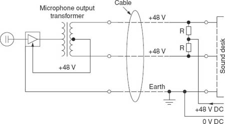
The power unit, which is remote from the microphone, provides 48 V d.c. (but note that there are other systems; see below), this being an accepted worldwide standard. The positive (+) output is ‘shared’ between the two signal-carrying wires of the microphone cable, while the important earth wire, which is usually in the form of braiding to give electrical screening of the signal wires, is connected to the negative (–) part of the supply. (This negative part can be described as being at 0 V.)
The vital point to realize is that both signal wires are at the same electrical potential and there is therefore no voltage between them. Consequently, almost any type of microphone could be connected to the system without harm – but there is an important exception which will be dealt with under the heading of ‘Balanced wiring’ (see below). The resistors R are of fairly high value – 6.8 kohm (kΩ) being preferred. This is high enough to limit the current in the event of an accidental short circuit.
Other powering systems exist, as we have said, but their use tends to be specialized and limited to a small range of microphones. The one described above is known variously as ‘48 volt phantom’ or ‘standard phantom’ powering.
The term ‘phantom’ appears to be derived from a system of telephony when three circuits were carried on two pairs of wires – one pair carrying one ‘leg’ of the third circuit and the other pair carrying the remaining ‘leg’ in a manner not unlike the powering system we have described. Because one of the telephone circuits had no separate physical existence of its own it was known as a ‘phantom’ circuit.
Balanced wiring
It is vitally important in things like microphone cables, where the voltages are very small, that all possible precautions are taken to minimize the risks of interference caused by mains hum and other sources being induced into the cable. Careful screening, mentioned above, obviously helps, but a major method of protection is to have both signal wires as similar to each other as possible. In brief, this means that any induced interference voltage is the same in each wire and can thus be ‘cancelled out’. Such an arrangement is called balanced wiring.
A particularly good example of this sort of cable is what is known as star-quad. There are four cables inside a screened outer. Imagine that the viewer is looking at the open end: they would see the four cables arranged in a sort of square. Opposite wires are connected together, and the four are twisted to make a spiral. This makes the arrangement as electrically balanced as possible.
Most domestic audio equipment is unbalanced and this can be quite satisfactory for short cable runs – up to a metre perhaps – but unbalanced microphone cables any longer than this are likely to pick up unacceptable amounts of hum and possibly other interference. This topic is dealt with more fully in Chapter 8, Part 2.
Linking together professional balanced equipment with nonprofessional unbalanced units is almost certainly going to be fraught with problems in the form of unacceptable hum – and maybe other unwanted effects like distortion. The balanced/unbalanced situation can often be cured with a suitable transformer, but this MUST be of the kind that gives complete isolation. What are termed ‘through earths’ – where an earth connection links primary and secondary – must be avoided.
It can safely be said that all professional microphones are provided with balanced outputs. Non-professional ones may not be.
There are obvious dangers in connecting non-balanced microphones to equipment providing phantom power. Because of the high-value resistors there is unlikely to be any damage, but it will probably mean that the microphone, especially if it is an electrostatic one, will not work.
It may be of interest to mention that television studios are regions of great hazard as sources of interference. In particular, the dimmer circuits of the lighting systems radiate large amounts of the harmonics of mains frequency. This problem has, in recent years, extended to even quite small halls and theatres, where ‘affordable’ electronic dimmer systems have become quite common. In a domestic environment fluorescent lights and wall-mounted dimmer units can be a frequent cause of trouble.
Radio microphone data
There is considerable variation between models and the following is no more than a rough guide:
Frequency |
around 174 MHz |
Transmitter power |
2–20 mW |
Transmitter battery life |
4–5 hours |
Range |
10–30 m, depending on circumstances. |
|
(more than 30 m is possible line-of-sight |
|
out of doors) |
Almost all make use of an f.m. system (= frequency modulation. The carrier frequency is made to vary in proportion to the microphone output voltage.)
A danger with radio microphones is that a performer with the microphone/transmitter who moves about a lot may enter a region where a reflection of the radio signal off a sufficiently large metal surface may cancel the direct signal at the receiver. When possible, all the positions in which the person may be should be checked in advance, although this is not always practicable.
The risk of radio black-spots can be greatly reduced by the use of a diversity receiver system. The latter has two receiving aerials spaced a short distance apart – perhaps a couple of metres – and the electronics in the unit continually monitor the outputs of the two aerials, switching instantly and silently to the one with the stronger signal. Diversity units are expensive but can be hired.
It may do no harm here to repeat the warning near the end of Part 1 of this chapter: in the UK, several frequencies are allocated for general use, although the equipment must be approved by the DTI (Department of Trade and Industry). This means that there may be other people in the vicinity operating radio microphones quite legitimately on the same frequency. Make enquiries beforehand if possible and be prepared to negotiate!
Questions
1. Phantom power is delivered to a microphone that needs it via
a. Special three-core cable |
b. Standard three-core microphone cable |
c. Three-core mains cable |
d. Two-core cable |
2. Which types of microphone are likely to need phantom power?
a. All types |
b. Ribbon |
c. Moving coil |
d. Electrostatic |