
4 Microphones
Part 1
Microphones are amongst the most important tools in any sound recording work and an understanding of their properties is vital. Fuller technical details can be found in books listed under ‘Further reading’ – here we must confine ourselves to an outline.
There are two principal characteristics of any microphone. One is the transducer system – in other words, the means by which sound waves are converted into electrical signals. The other is the polar response – the way in which the microphone responds to sounds arriving from different directions. We will look at these two things in turn, but first we will look briefly at the main components of a microphone. These are:
1. The diaphragm. This is a thin circular sheet of metal or plastic which is caused to move by the varying pressures of an incident sound wave. It is invariably placed behind a protective metal grille or a piece of metallic gauze. The diaphragm either forms part of, or is mechanically linked to, the transducer.
2. The transducer. This can be one of a number of forms which are outlined below.
3. The microphone casing. Besides protecting the diaphragm and transducer, the nature of the casing affects the polar response of the microphones, as explained in Part 2 of this chapter.
Microphone transducers
The following is a brief description of the most important types.
1. Moving coil
Figure 4.1 shows a simplified section through a transducer of this type. The diaphragm is slightly domed to give it extra rigidity and fixed to it is a coil of very thin wire, often of aluminium because of this metal's lightness. The outside area of the domed section is corrugated to allow the diaphragm to vibrate. As it does so, the movements of the coil in the magnetic field cause a voltage to be generated in it. This voltage is extremely small – of the order of 1 millivolt (one thousandth of a volt) or less – and is a replica of the diaphragm movements and hence of the sound waves which are striking it.
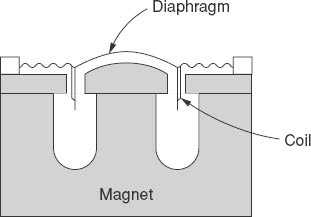
Figure 4.1 Moving coil microphone
Moving coil microphones are sometimes called ‘dynamic’ microphones. This doesn't seem to me to be a very good term, as ‘dynamic’ simply means a system in which things are constantly changing – as opposed to ‘static’. Any microphone, therefore, is in a sense dynamic. It's far better to call these microphones ‘moving coil’, which says what they are!
2. Ribbon microphones
Figure 4.2 shows the idea.
Here the very thin corrugated ribbon is itself the diaphragm. Its movement to and fro causes a voltage to be induced in it, but because the total length of the ribbon is relatively small, being rarely more than a couple of centimetres, the induced voltage is also very small, generally much less than that produced in the coil of a moving coil microphone.
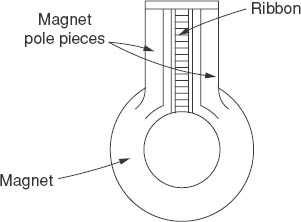

Figure 4.3 Basic electrostatic microphone
3. Electrostatic (‘condenser’) microphones
The diaphragm and backplate form a capacitor. As the diaphragm vibrates the capacitance varies and, as is explained a little more fully in Part 2, a corresponding voltage is produced. Electret microphones are a form of electrostatic microphone and are mentioned further in Part 2.
Other types of transducer exist but they are not of great importance today. For the sake of completeness though, we might mention the carbon granule microphone. A layer of small grains of carbon is held between the diaphragm and a rigid plate. Vibrations of the diaphragm cause the pressure on the granules to change and this varies their electrical resistance. A current (produced by, say, a battery) flowing through the granules is thus caused to vary also. For many years, this type of transducer was used in telephones and it was widely used in the very early days of broadcasting. Its drawbacks are that it generates a very detectable hiss in its output, apparently caused by minute electrical arcs between the granules, it is less reliable than more modern types and it is not easy to have different polar diagrams – a point which will be better appreciated when that topic is dealt with a little later. Also, the granules tended to pack together so the whole thing had to be tapped firmly from time to time. The carbon microphone's advantages were that it gave a high output and it was cheap. It is very rarely encountered now.
Another type of microphone which is obsolete in the broadcasting/recording world but might be found occasionally in second-hand shops is the crystal microphone. Carefully chosen slices of crystals of certain materials show what is known as the piezo-electric effect. In other words,
Table 4.1 Comparison of moving coil, ribbon and electrostatic microphones
Moving coil | ||
For: |
(a) |
Usually very reliable and robust (although all microphones should be treated with as much care as possible). |
|
(b) |
Can be used on the end of considerable lengths of cable without the need for amplifiers close to the microphone (unlike electrostatic microphones which, for reasons given in Part 2, have to have some form of amplifier near to the microphone). |
Against: |
(a) |
Tend to be expensive as skilled labour is needed in their assembly. |
|
(b) |
The quality of their output, although as a rule good, is not likely to match that of a high-grade electrostatic microphone. |
Ribbon | ||
For: |
(a) |
The quality can be very good indeed because of the extreme lightness of the ribbon. |
Against: |
(a) |
Rather fragile. |
|
(b) |
Cannot normally be used out of doors as the slightest wind on the ribbon causes serious rumble noises in the output. |
|
(c) |
Usually expensive. |
Electrostatic | ||
For: |
(a) |
Excellent quality is possible. |
|
(b) |
While the very best microphones of this type are costly, reasonable quality microphones can be quite cheap. |
Against: |
(a) |
For reasons explained in Part 2 it is necessary to have an amplifier close to the diaphragm assembly, either within the body of the microphone or not more than about a metre away. Generally, though, when one buys an electrostatic microphone one gets the complete unit. |
|
(b) |
Apt to be affected by moisture – not necessarily permanently but if, for example, one is taken from a cold environment into a warm room there is a likelihood of condensation causing loud crackling or ‘frying’ noises in the output until the microphone has dried out, which, even in a warm room, might take some time. Placing the microphone on a warm (but not too hot!) radiator speeds up the drying-out process. |
when the piece of crystal is deformed a small voltage is generated. Quartz is one such material and the ubiquitous quartz watch makes use of this electro-mechanical property to give very accurate time keeping. The crystal microphone suffers from a number of disadvantages, one being that crystals appear to vary in their acoustic properties, so that while quartz is good in watches it is less satisfactory than other types of transducer in microphones.
Polar responses
It might be imagined that a microphone ought to respond equally well to sounds arriving from all directions. In some cases this is what is wanted, but lack of sensitivity to certain angles of incidence can be invaluable in discriminating against unwanted noises. The best way of illustrating the directional characteristics of a microphone is by means of a polar diagram, such as that shown in Figure 4.4. The microphone itself is imagined to be at the centre of the diagram and the distance from there to the heavy line at any angle is proportional to the sensitivity of the microphone to sounds arriving at that angle. The scale from the centre outwards may be in voltage or, more usefully, in decibels. The line marked 0° is taken to represent the direction in which the microphone is facing, so that 90° and 270° represent the sides and 180° the rear.
There are several basic polar diagrams which are (a) reasonably easily achieved by manufacturers and are (b) found to be useful for different applications. Some of these are listed below, but a fuller explanation is given in Part 2.
1. Omnidirectional
Figure 4.4 shows the polar diagram for a microphone which responds equally well to sounds from all directions – hence the name omnidirectional. Note the little sketch of the microphone with the significant directions.
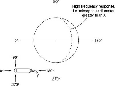
Figure 4.4 Polar diagram for an omnidirectional microphone
In practice, a suitably designed microphone of this type, unless it is very small indeed, can be omnidirectional only up to a certain frequency. This is because, to respond to sound waves arriving from behind (180°), the sound wavelengths must be appreciably longer than the dimensions of the microphone if they are going to diffract round it. The dotted line in Figure 4.4 shows, in a much simplified way, the response that can be expected at the higher audio frequencies from a microphone having a diameter of 2 cm.
(An important point is that polar diagrams have to be drawn in two dimensions, but they actually refer to a three-dimensional concept. Thus, a true polar diagram for an omnidirectional microphone is a sphere and not a circle. This should be remembered with all other polar diagrams.)
2. Figure-of-eight
As will be seen from Figure 4.5, the name is self-explanatory.
This pattern is achieved by allowing sound waves to reach both sides of the diaphragm. Ribbon microphones lend themselves particularly well to being figure-of-eight, but electrostatic microphones of the more expensive type can also be made to have this response. It can be a very useful pattern as unwanted sounds from the sides are discriminated against.
Face-to-face interviews in poor (e.g. excessively reverberant) conditions are an obvious application. However, figure-of-eight microphones tend to be rather prone to producing severe rumble noises in their output when they are handled and also, being susceptible to the effects of wind, they are not suitable for outdoor work. Consequently, they are often of little use except in a good studio environment. Furthermore, the high cost of almost all figure-of-eight microphones tends to limit their use in the non-professional world.
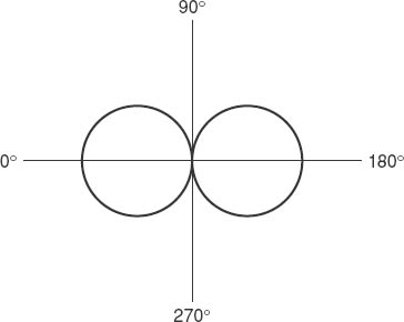
Figure 4.5 Figure-of-eight polar diagram (A true representation would be two touching spheres)
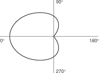
3. Cardioid
Figure 4.6 shows the heart-shaped pattern which explains the name. (It's taken from a Greek word meaning ‘heart’ – hence words like ‘cardiogram’.)
This is probably the most useful of all the responses listed here. It should be pointed out, though, that the response at 180° is, in practice, never zero. The reduction in sensitivity compared with sounds from the front (0°) is unlikely, even in a very expensive professional microphone, to be more than about 25–30 dB and at some frequencies (usually the low ones) will almost certainly be less. Nevertheless, a reduction of even this is enough to be very useful. Remember that, subjectively, a reduction of 20 dB will make a sound seem about a quarter as loud.
The ‘dead’ (rear) side can often be directed towards unwanted noises and the response at the sides (90° and 270°) of the microphone is lower than the 0° response by about 6 dB, which is helpful at times.
4 Hypercardioid
This is a diagram which is intermediate between figure-of-eight and cardioid (Figure 4.7). Its most obvious characteristic is that there are two ‘dead’ angles, each at about 45° off the rear axis. The term ‘super-cardioid’ is sometimes used to imply a similar pattern.
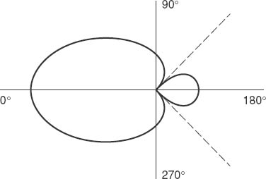
Figure 4.7 Hypercardioid pattern
5. ‘Gun’ patterns
The name is derived from the shape of the microphone required to produce this pattern, being usually an extended tube with a diameter of 2–3 cm. There are two general versions characterized by the length of the tube: ‘short’ guns, about 25 cm long, and a longer type with a tube length of around 50 cm. The short tube microphones have a polar response which is not unlike a hypercardioid – and indeed are often described as being this. The longer tube microphones have a more directional response. Typical curves are shown in Figure 4.8.
Note that each type becomes more directional as the frequency increases, and both are relatively non-directional at low frequencies. Microphones of this kind are very widely used, especially for outdoor drama and news-gathering operations, when their marked ability to reduce the effects of sounds which do not arrive from the front of the microphone allows them to be used much further from the action than is possible with other types.
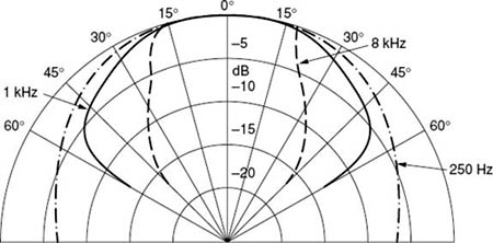
Figure 4.8 Typical ‘gun’ microphone responses
Gun microphones tend to be very expensive indeed, but can often be hired at quite reasonable rates for the day or the week. One very important practical point to note is that these microphones tend to lose their directional properties in small rooms – but one might wonder why anyone would want to use such a device for sound pick-up in a small room!
‘Boundary’ microphones
There is a category of microphones which has achieved significance in the last decade or two, consisting of a conventional microphone unit (usually electrostatic and inherently omnidirectional) mounted very close to the centre of a metal plate or in the surface of a block of wood. The term ‘boundary’ is only one description. They are sometimes referred to by the trade mark name of ‘Pressure Zone’ microphones. Such microphones are best used when placed on a large flat surface such as a table or even the floor, when their polar response becomes, almost inevitably, hemi-spherical. They are fairly immune to vibration effects and can thus be useful for round-the-table conferences or other meetings, when the microphone is placed, naturally, in the centre of the table. Adequate sound pick-up, perhaps not for serious reproduction but quite good enough for subsequent preparation of a transcript, can be obtained with the microphone on the floor in the centre of a room, with perhaps as many as 20 or 30 people present and all likely to contribute to the discussion.
Personal microphones
The little microphones which are often clipped to a presenter's clothing come into this category. They are usually omnidirectional electrostatic devices and have two advantages: (1) they are very inconspicuous and (2) if the person moves about then the microphone moves with them. They are sometimes called ‘lapel microphones’ or ‘tie-clip microphones’. Another term, really quite incorrect, is ‘Lavalier microphones’. This term was used for the first personal microphones which were on a kind of lanyard worn round the neck. It is said that the word came about because a certain Madame Lavalier in the court of a French King used to have a pendant made of very large jewels!
Radio microphones (‘wireless microphones’)
Both terms are slightly inaccurate, although it is not easy to think of convenient and more suitable ones! The Americans use the term ‘wireless microphone’ and one sees what they mean – there are no cables, but there are wires inside the device!
To begin with, the actual microphone is perfectly conventional. In principle, any type could do. The ‘radio’ refers to the link between the microphone and the next part of the chain of equipment. This link is usually an f.m. (frequency modulated – see Part 2) radio system, consisting of a small, low-power transmitter at the microphone end and a matching receiver at the other end. The transmitter is battery operated and may be built into the microphone body – in which case the aerial is commonly a short rod or piece of flexible wire sticking out of the base of the microphone – or it may be a separate unit to go into a pocket or be otherwise hidden in the clothing. The latter system is the preferred one if, for visual reasons, the microphone and its transmitter have to be as inconspicuous as possible. The microphone itself is then likely to be of the ‘personal’ type, which can be hidden if necessary.
The receiver generally has a short aerial fitted to the case and it may be mains powered. The range of the average radio microphone is around 30 m – greater than this in good conditions, less in others. Care has to be exercised when more than one transmitter/receiver pair is used at the same site, as each needs to use a different radio frequency to avoid interference. Also, it is not unknown for radio microphones being used by a quite different organization in the near locality to cause mutual interference.
Good radio microphones are expensive and unless they are going to be used regularly – say more than once or twice a week throughout the year – it is best to hire them.
Questions
1. Which of the following statements are correct about moving coil microphones?
a. |
They need to have an amplifier close to them |
b. |
They are generally robust and reliable |
c. |
The quality of their output, while good, is likely to be inferior to some other types |
2. Which of the following statements are correct about ribbon microphones?
a. |
They are usually fragile |
b. |
Very good quality is possible because of the lightness of the ribbon |
c. |
They are cheap |
3. Which statement best describes a figure-of-eight polar pattern?
a. |
It is like a figure 8 on its side |
b. |
It is like a figure 8 upright |
c. |
It is like two spheres in contact |
4. A good cardioid microphone's sensitivity to sound from the rear is lower than the front sensitivity at best by about
a. 10–12 dB |
b. 25–30 dB |
c. 50–60 dB |
d. more than 80 dB |
5. A hypercardioid microphone has two ‘dead’ angles. These are approximately
a. 45° on each side of the front |
b. 90° on each side of the front |
c. 45° on each side of the rear |
d. 270° on each side of the rear |