
16 Analogue Recording and Reproduction
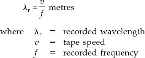
Formulae
Magnetomotive force, m.m.f is given by
m.m.f. = NI
where N is the number of coil turns and I is the current.
The units of m.m.f are ampere turns/meter (At/m)
The intensity or field strength is the total force acting per unit length I of the magnetic circuit. It is called the magnetizing force H.
H = m.m.f./l = NI/l(AT/m)
The magnetizing force causes a flux Ф in the magnetic circuit.
The flux density B is the flux per unit area. The unit is the tesla (= webers/m2).
Ф = m.m.f./S
where S is the reluctance of the circuit.
Figure 73 shows a typical BH loop (hysteresis loop).

Figure 73 Hysteresis loop
Magnetic Tape – Typical Characteristics
Base material – Mylar
Base thickness – 25 to 40 μm
Coating, commonly ferric oxide (Fe2O3) in the form of needle-shaped particles roughly 0.6 to 1 μm in length and less than one-tenth of that in diameter.
Coating thickness – 10 to 15 μm.
Tape Transfer Characteristic
Figure 74 shows the distortion that would arise if corrective measures (bias) were not applied.

Figure 74 Tape transfer characteristic
Tape Head Data
Typical head gaps for 38 cm/s (15 in/s) tape speeds:
Erase head: ~ 100 μm
Record head: ~ 20 μm
Replay head: ~ 5-10 μm or less
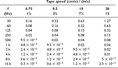
Recorded Wavelengths
The recorded wavelength is the length on the tape of one cycle of the recorded signal.
Tape width |
Typical use |
|
(mm) |
(in.) |
|
3.8 |
5/32 |
Cassettes |
6.25 |
1/4 |
Mono full-track, 1 or 2 track, stereo |
12.5 |
1/2 |
Stereo mastering, 4 track |
25 |
1 |
4-track mastering, 8 track |
50 |
2 |
16 track, 24 track |
In the table below the recorded wavelengths are given in cm.
Comparison of hysterisis loops for tape material and head cores
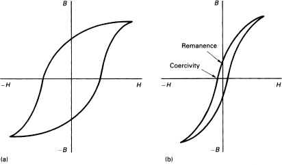
Figure 75 Hysteresis loops for (a) ‘hard’ magnetic material – tape oxide; (b) ‘soft’ – head core material
Bias Frequency
This should be about 4–6 times the highest recorded signal – i.e. around 100 to 150 kHz. Lower bias frequencies may result in undesirable intermodulation products. For example, if the bias frequency were 30 kHz and the highest audio frequency were 18 kHz then there will be sum and difference intermodulation frequencies of 48 kHz and 12 kHz, the latter falling into the audible range.
Optimum Bias Setting
This is represented graphically in Figure 76.
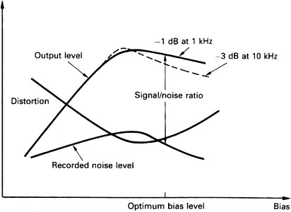
Figure 76 Illustrating optimum bias setting
Used to compensate for losses caused by the gap length, the thickness of the tape coating and in the pole pieces, etc.
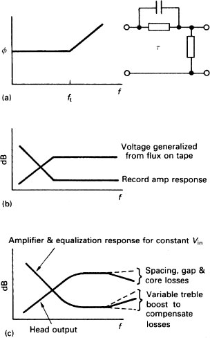
Figure 77 (a) Equivalent circuit of a standard replay response; (b) replay head and amplifier response for an ideal head; (c) real replay head and amplifier responses
Standard Equalizations in IEC and NAB Standards
These are given as the relevant time constants τ, where
![]()
Tape speed |
IEC1 |
IEC2 and NAB |
9.5 cm/s; 3/75 in/s |
- |
50 Hz; 1800 Hz |
|
|
3150 μs; 90 μs |
|
|
(NAB only) |
19 cm/s; 7.5 in/s |
0 Hz; 2240 Hz |
50 Hz; 3150 Hz |
|
(∞, 70 μs) |
(3150 μs; 50 μs) |
38 cm/s; 15 in/s |
0 Hz; 4500 Hz |
50 Hz; 3150 Hz |
|
(∞, 35 μs) |
(3150 μs; 50 μs) |
76 cm/s; 30 in/s |
(IEC1 not used) |
AES 1971 |
|
0 Hz; 4500 Hz |
0 Hz; 9000 Hz |
|
(∞, 35 μs) |
(∞ μS; 17.5 μs) |
Head Track Formats
See Figure 78.

Figure 78 Head track formats
Cassettes
Track layout. See Figure 79.
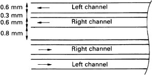
Figure 79 Audio cassette tape
Mechanical Adjustments of a Tape Head
See Figure 80.
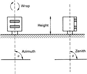
Figure 80 Illustration of azimuth and zenith adjustments
Level
The tone section of a tape is usually recorded at 700 Hz or 1 kHz. The exact frequency is not usually critical. The exact level is, however, important. It is taken as the 0 dB reference but if it is not the reference fluxivity required the example on page 121 shows how to make a correction.
Assume that the machine needs to be aligned to the NAB characteristic at 320 nWb/m for 0 VU = +4 dBm. The reference fluxivity on the tape is 200 nWb/m. The reference fluxivity difference is calculated from
![]()
In the example given above:
![]()