
26 Digital Interfacing and Synchronization
The AES/EBU Interface
(AES = Audio Engineering Society; EBU = European Broadcasting Union).
This format allows two channels of digital audio to be transferred serially over one balanced interface using RS422 drivers and receivers. Figure 138 shows the hardware. This allows the two channels to be transferred over distances up to 100 m.
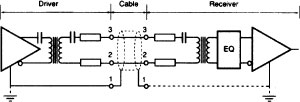
Figure 138 AES/EBU hardware interface
The format of the ‘sub-frame’ is shown in Figure 139.

Figure 139 AES/EBU subframe format
The ‘Sync’ bits can be one of three patterns which identify which of the two channels the sample represents or marks the start of a new channel status block. ‘Aux’ carries additional data. See also Figure 140.
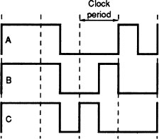
Figure 140 AES/EBU sync patterns. A is the start of the A-channel sub-frame, B is the start of the B-channel sub-frame and C is the start of a new channel status block
The Sony–Philips Digital Interface (SPDIF)
This is very similar to the AES/EBU interface with only subtle differences from it.
Sony Digital Interface (SDIF)
The common version is the SDIF-2 which is used mainly for the transfer of audio data from SONY professional digital audio equipment, particularly the PCM-1610 and 1630, and also on some semi-professional equipment (see Figure 141).
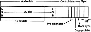
Figure 141 SDIF-2 data format
Mitsubishi Interfaces
Mitsubishi ProDigi format machines use an interface similar to SDIF but not compatible with it. Separate interconnections are used for each audio channel. ‘Dub A’ and ‘Dub B’ are 16-channel interfaces found on multi-track machines; Dub A handling tracks 1–16 and Dub B handling tracks 17–32. The pin assignments are shown below.
Dub A:
Pin |
Function |
1,18 |
Ch.1(+/–) |
2,19 |
Ch.2(+/–) |
3,20 |
Ch.3(+/–) |
4,21 |
Ch.4(+/–) |
5,22 |
Ch.5(+/–) |
6,23 |
Ch.6(+/–) |
7,24 |
Ch.7(+/–) |
8,25 |
Ch.8(+/–) |
9,26 |
Ch.9(+/–) |
10,27 |
Ch.10(+/–) |
11,28 |
Ch.11(+/–) |
12,29 |
Ch.12(+/–) |
13,30 |
Ch.13(+/–) |
14,31 |
Ch.14(+/–) |
15,32 |
Ch.15(+/–) |
16,33 |
Ch.16(+/–) |
34,35 |
Bit clock(+/–) |
36,37 |
WCLK(+/–) |
38,39 |
Rec A(+/–) |
40,41 |
Rec B(+/–) |
17,50 |
GND |
Dub B:
Pin |
Function |
1,18 |
Ch.17(+/–) |
2,19 |
Ch.18(+/–) |
3,20 |
Ch.19(+/–) |
4,21 |
Ch.20(+/–) |
5,22 |
Ch.21(+/–) |
6,23 |
Ch.22(+/–) |
7,24 |
Ch.23(+/–) |
8,25 |
Ch.24(+/–) |
9,26 |
Ch.25(+/–) |
10,27 |
Ch.26(+/–) |
11,28 |
Ch.27(+/–) |
12,29 |
Ch.28(+/–) |
13,30 |
Ch.29(+/–) |
14,31 |
Ch.30(+/–) |
15,32 |
Ch.31(+/–) |
16,33 |
Ch.32(+/–) |
17,50 |
GND |
Dub C:
Pin |
Function |
1,14 |
Left(+/–) |
2,15 |
Right(+/–) |
5,18 |
Bit clock(+/–) |
6,19 |
WCLK(+/–) |
7,20 |
Master clock(+/–) |
12,25 |
GND |
This is often used with Yamaha digital audio equipment to allow a number of devices to be operated in cascade. The interface terminates in an 8-pin DIN-type connector and carries two channels of 24-bit audio data over an RS422-standard differential line.

Figure 142 Yamaha interface connector pins
Pin |
Function |
1 |
WCLK + |
2 |
GND |
3 |
Audio data — |
4 |
WCLK — |
5 |
Audio data + |
6 |
20 μH coil to GND |
7 |
20 μH coil to GND |
8 |
GND (in), ENABLE (out) |
The 20 μH inductors on Pins 6 and 7 are for suppression of r.f. interference.
Timing for Synchronous Signals
More than one reference signal may be used for locking the sampling-rate clock of a digital audio device. In a large system it is vital that all devices remain locked to a common sampling rate reference clock and there are AES recommendations for this. Input signal frame edges must lie within ± 25% of the reference signal’s frame edge, and output signals within ± 5%, although tighter accuracy than this is preferable. (See Figure 143.)

Figure 143 Timing stipulations for synchronous signals