
Basic Requirements
Before purchasing microphones for high quality applications, such as recording or broadcasting, the following check-list should be considered.
Sound Quality
1. Is the frequency response satisfactory? Ideally this should be ± 2 dB over the range 20 Hz to 20 kHz but less tight tolerances may be acceptable at the high and low frequency ends. There can be advantages in a non-flat response for some specialized purposes: a reduced bass response can be an advantage in public address situations, for example.
2. Transient response. This is not easy to assess except by listening tests, which should be done with a wide range of sound sources.
3. Sensitivity. Is the electrical output adequate bearing in mind the situations in which the microphone will be used?
4. What is the self-generated noise? This is sometimes quoted as the equivalent acoustic noise in dBA. For digital recording work the microphone’s noise level should obviously be as low as possible.
5. What is the maximum sound pressure level which can be handled without distortion? (Note that the limit is generally set at the first stage of amplification, which in the case of electrostatic microphones is inside the microphone itself.)
6. How much variation is there between different samples of microphone of the same type? This may be considerable with cheap devices.
7. What is the directivity pattern (polar diagram)?
8. How much does this vary with frequency and does it depend on the orientation of the microphone: i.e. is it different in the vertical plane compared with the horizontal plane?
9. Is the directivity fixed or variable? If variable is the control on the body of the microphone or is there a remote unit? What patterns are available and how good are they?
Physical
10. Physical dimensions.
11. Weight.
12. Appearance, including colour and finish: e.g. matt or shiny.
Reliability
13. Can trouble-free service be expected? This can probably only be ascertained by referring to other users with experience of this microphone.
14. Does it appear to be robust?
15. Are there any reasons for thinking that there might be deterioration with age and use?
16. How likely is it that on-site maintenance can be carried out, how available are spares, what repair service, including turn-round time can the manufacturers offer?
Vulnerability
17. Is it prone to wind noise, ‘popping’, etc?
18. Is there a windshield available? If so how effective is it (are they)?
19. To what extent is the microphone likely to be affected by humidity and temperature?
20. Is it reasonably immune to external magnetic and electrostatic fields, including r.f. pick-up?
21. How prone is it to the effects of vibration, handling noise, cable rustle, etc.?
Electrical
22. What is the optimum electrical load?
23. What power supplies does it need, if any?
24. If capable of being battery-operated what is the battery life and how readily available are the batteries?
25. Connectors. Are these standard?
26. Is there built-in frequency correction, e.g. a bass-cut switch?*
27. Is there a built-in, switchable, attenuator?*
(* The absence of these facilities does not necessarily imply an inferior microphone as it may well be that there is never likely to be a need for them.)
Miscellaneous
28. What types of mounting are available?
29. What is the cost?
30. What is the reputation of the manufacturer?
31. If made abroad are there good agents in this country?
See table on following page.
Moving coil
The sensitivity of the average moving coil microphone is such that an e.m.f. of the order of 0.5 to 1 mV is produced with normal speech at a distance of 0.5 m.
Microphone sensitivities in commonly-used units
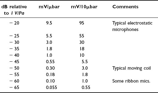

Figure 19 Moving coil microphone (simplified)
1. Usual directivity patterns are cardioid, omnidirectional or ‘gun’. Figure-of-eight responses need two back-to-back units and have rarely been satisfactory.
2. Reasonably immune to humidity and temperature.
3. Moderately robust.
4. They have the advantage of not needing power supplies.
Ribbon
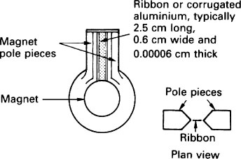
Figure 20 Basic ribbon microphone
The ribbon impedance is usually of the order of 1 Ω and a built-in transformer is used to raise the impedance at the output to a much higher value. This has the added benefit of raising the output voltage but even so this is small, being less than 1 mV for normal speech at a distance of 0.5 m.
Typical characteristics:
1. The most usual directivity patterns are figure-of-eight or hypercardioid.
2. Fragile. The ribbon needs to have effective screening from air blasts inside the microphone casing. They are therefore not suitable for use out of doors.
3. Sensitivity is almost always low.
4. A specialized use is in the ‘lip ribbon’ microphone used for commentaries in noisy environments (see later).
The combination of low sensitivity, relative fragility and limited range of directivity patterns means that ribbon microphones tend to be used rarely, the lip ribbon being something of an exception.
Electrostatic
In simple form the basic circuit for an electrostatic (sometimes called ‘condenser’ or ‘capacitor’) microphone is shown in Figure 21.

Figure 21 Essential circuit for an electrostatic microphone
The spacing between diaphragm and back plate is typically about 0.02 mm, forming a capacitor of value about 20 pF. The d.c. supply may be in the range 50 V to 100 V, with R having a very high value of several hundred MΩ. The effect is to give a relatively long time constant to the CR combination. Then, with a variation of δC in the capacitance there is a change of the voltage given by
δV = Q δ C
Electrets – materials with a permanent electrostatic charge are often used either for the back plate or the diaphragm and this removes the need for a polarizing voltage.
r.f. electrostatic – the capsule forms part of an LC circuit which in turn is part of an r.f. discriminator. The output of an oscillator, typically about 8 MHz, is fed into the discriminator. The output of the latter is an audio signal representing the variations of the capsule’s capacitance.
The advantage of this type of transducer is that it is largely unaffected by humidity, although the cost is likely to be high (see Figure 22).

Figure 22 Simplified r.f. electrostatic microphone
Typical characteristics of electrostatic microphones.
1. Good frequency response because of the lightness of the diaphragm. The high frequency response is generally very good because the diaphragm is under tension, resulting in a high resonant frequency.
2. High sensitivity.
3. All types of directivity pattern (polar diagram) can be produced.
4. Prone to humidity problems, although careful drying in a warm environment can generally restore normal operation within 30 to 60 minutes.
Directivity Patterns (Polar Diagrams)
Omnidirectional
Essentially the result of pressure operation on the diaphragm – i.e. the force on the diaphragm depends on the sound wave pressure only and not a derivative of it.
‘Omni’ microphones are only truly omnidirectional when the incident sound wavelengths are large compared with the microphone diameter.
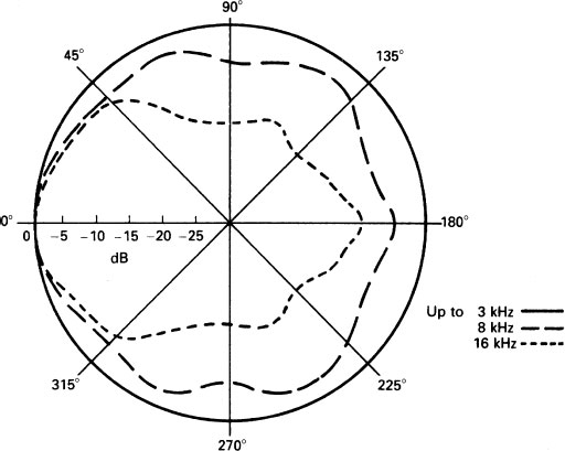
Figure 23 Directivity patterns for a typical ‘omni’ microphone
A useful approximate calculation to find the frequency up to which the microphone is omnidirectional results from finding the frequency corresponding to the diameter of the microphone. The microphone will be reasonably omnidirectional up to frequencies between two and three octaves below that.
For example, a microphone has a diameter of 2 cm. The frequency corresponding to 2 cm wavelength is 17 kHz. One octave below this is about 8 kHz; two octaves, 4 kHz; three octaves, 2 kHz. Thus this microphone will be reasonably omnidirectional up to about 3 kHz.
Phase cancellation, i.e. a reduction in sensitivity to sounds from the side, may also occur when there is a complete wavelength, or approximately so, across the diaphragm, as shown in Figure 24.
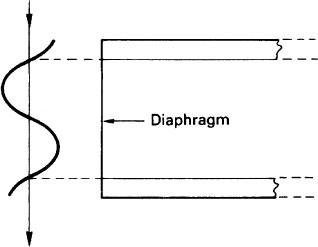
Figure 25 shows the frequency response at different angles of sound incidence for a typical omni microphone.
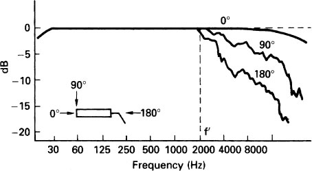
Figure 25 Typical omni microphone frequency response graphs
General characteristics of omni microphones are:
1. Usually less affected by rumble and handling noise than other types.
2. Do not exhibit proximity effects (see under figure-of-eight microphones).
3. While not offering any advantages in rejection of sounds from certain angles their relatively constant sensitivity, except at high frequencies, can sometimes be useful.
Figure-of-eight microphones
The force on the diaphragm results from the pressure gradient (pressure difference) between its two sides.
A figure-of-eight pattern may be represented by
r = cos θ
where r is the effective sensitivity at angle θ.
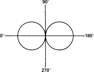
Figure 26 Figure-of-eight polar diagram
The pressure gradient may be calculated from
![]()
where FG is the pressure gradient, Ff and Fr are the forces on the front and rear of the diaphragm respectively, and β is the angle found from
![]()
d being the acoustic distance between the front and rear of the diaphragm, f the frequency and c the velocity of sound.
Figure 27 illustrates the above.
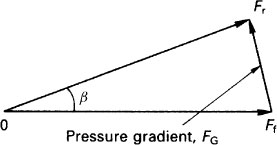
Figure 27 Method of determining the pressure gradient
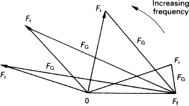
If the distance of the sound source is large compared with d so that inverse-square-law effects can be neglected the expression for FG simplifies to
![]()
The variation in pressure gradient with frequency is illustrated in Figure 28.
Proximity effect (‘Bass tip-up’)
This is shown when the source of sound is close to the microphone so that, because of inverse-square-law effects, Ff and Fr are not equal and the frequency f is low so that β is small. The result is that the output of the microphone for low frequency sounds becomes exaggerated (see Figure 29).
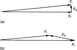
Figure 29 Proximity effect
The effect is used to good advantage in certain microphones used by radio or out-of-vision television commentators – the so-called ‘lip ribbon’ microphone. Bass cut restores the voice to an approximately normal response but reduces the level of distant l.f. noises.
The table below gives the increase in microphone output, relative to the output at 10 kHz for a typical microphone of this type.
General characteristics of figure-of-eight microphones:
1. Very prone to rumble and vibration.
Proximity effect for a pressure gradient microphone (for a point source, 50 mm from daphragm)
Frequency |
Relative output |
(Hz) |
(dB) |
50 |
26 |
100 |
20 |
200 |
14 |
500 |
7 |
1k |
3 |
2k |
1 |
10 k |
0 |
2. Show proximity effect (see above).
3. The figure-of-eight pattern is generally fairly well maintained with frequency although the nulls at 90° to the axis may be poorly defined at some frequencies.
Cardioid
The cardioid pattern in Figure 30 is a plot of
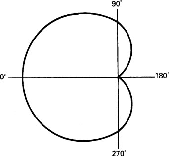
Figure 30 Cardioid pattern
r = 1 + cos θ
In practice this is rarely obtained with a ‘cardioid’ microphone. The frequency response graph of a typical high-grade unit is shown in Figure 31 from which it can be seen that the 180° response, far from being zero, may be no more than about 10 dB below the axial response at low frequencies, and possibly even worse at high frequencies.
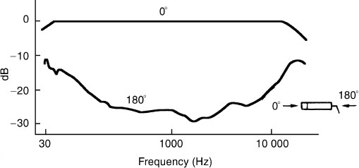
Figure 31 Typical cardioid frequency response graphs
General characteristics of cardioid microphones:
1. Usually show some proximity effect.
2. Tend to be prone to rumble and vibration effects.
Hypercardioid
The term ‘hypercardioid’ is often used for any microphone with ‘dead’ angles in the rear quadrants, but the most common usage is for dead angles at 45° off the 180° axis. (See Figure 32.) The equation in that case is
![]()
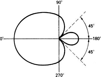
Hypercardioid microphones can be thought of as being half way between figure-of-eight and cardioid microphones, and their general characteristics reflect this.
General characteristics of hypercardioid microphones:
1. Proximity effect is typically less than for cardioids but more than for figure-of-eights.
2. Rather prone to rumble effects.
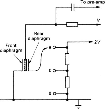
Variable directivity microphones
The capsule of a variable-directivity microphone normally consists of two back-to-back electrostatic cardioid microphones, the potential on the diaphragm of the rear unit being variable as shown in Figure 33.
Highly Directional Microphones
Interference-tube (‘Gun’) microphones (see Figure 34).
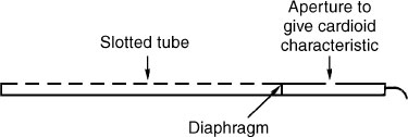
Figure 34 Simplified interference tube
Typical polar diagrams are given in Figure 35.
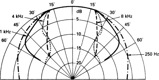
Interference tube microphones of about 250 mm length often have polar patterns which are close to hypercardioid in shape.
Phantom power systems
1. 48 V standard systems (sometimes indicated by a ‘P’ in the type number).
The resistors R, in Figure 36, are for current-limiting in the event of a short circuit. A common value is 6.8 kΩ.
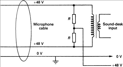
Figure 36 48 V phantom power – the supply end
2. A=B powering
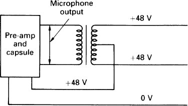
Figure 37 48 V phantom power – microphone end

Figure 38 A–B powering
A–B powering is generally a low-voltage method – typically 7–9 V – used with single microphones, whereas the 48 V system is usually applied to all the microphones in a studio. It has the advantage that only two wires are needed. The disadvantage is that a phase reversal will result in the failure of the microphone to work until the reversal is corrected.