
6 Diffuse Irradiance
A little later in the morning, if one hides the solar disk by holding the tip of a single finger at arm’s length before his eyes, the deep blue sky color holds right up to the edge of the sun itself.
Abbot Charles Greeley
(1872–1973)
6.1 Introduction
Diffuse horizontal irradiance (DHI) is defined as the solar irradiance that has been scattered by molecules, aerosols, and clouds in the atmosphere and received on a horizontal surface (refer to Figure 6.1). Another perspective on diffuse irradiance is that DHI is the skylight portion of the global horizontal irradiance (GHI) remaining after removing the direct normal irradiance (DNI). DHI is measured by a properly shaded pyranometer, or it can be computed from measurements of DNI and GHI using Equation 4.1. Light reflected by objects above the surface contributes to the DHI, but light reflected from the horizontal surface is not included. However, the radiation reflected from the surface that is subsequently reflected back to the surface by the atmosphere is included; that is, multiple scattering components are included in DHI.
A very clear atmosphere gives the sky a deep blue color because of Rayleigh scattering of solar radiation by air molecules. (Scattering and absorption of solar radiation will be discussed in more detail in Chapter 12.) This blue color is produced because air molecules scatter radiation nearly inversely with the fourth power of the wavelength, that is, scattering ∞λ–4. The sun appears yellow or red near the horizon since Rayleigh scattering preferentially removes the bluest light from the transmitted DNI.
Aerosol-scattered light depends on the aerosol particle size. For “typical” continental aerosols, the scattering is approximately ∞λ–1.3. Heavily polluted skies typically have an even larger negative exponent, and they scatter blue light preferentially, but not as strongly, as in Rayleigh scattering. This wavelength dependence for aerosols is most noticeable in extremely polluted conditions where the solar disk appears red even with the sun high in the sky, when the amount of Rayleigh scattering would ordinarily be insufficient to cause noticeable reddening. Although the sun’s disk appears red for these hazy conditions, skylight appears not blue but milky white, especially near the horizon because all photons are scattered multiple times during these heavy pollution episodes. The range of sky color from dark blue to milky blue to milky white is a rough gauge of the amount of aerosol in the atmosphere.
Cloud particles have large sizes relative to visible wavelengths, and their scattering wavelength dependence is nearly neutral; therefore, they appear to have the white color of the sun. The spatial distribution of skylight is complex and unpredictable for partly cloudy conditions but can be described mathematically for some conditions. Moon and Spencer (1942) developed a simple and useful approximation of the spatial distribution of skylight for thick uniform clouds. This sky is, basically, three times brighter in the zenith than at the horizon and varies as the cosine of the zenith angle (the angle from the zenith position, not the solar zenith angle). For very clear skies, where Rayleigh scattering dominates, the skylight is roughly half as bright 90° from the sun as it is near the sun. This is not quite correct because of multiple scattering (photons scattered more than once) that occurs in the real atmosphere. Cloudless but aerosol-laden skies are an intermediate case with respect to the complexity of mathematically describing the spatial distribution of skylight. Figure 6.2 is a low-resolution image of the skylight distribution for clear conditions with moderate aerosol. A disk normally blocks the area of the sky surrounding the sun, but in spite of this there is an enhanced bright aureole around the sun, called circumsolar radiation. A bright horizon caused by multiple scattering skirts the image. As for Rayleigh skies, there is minimum sky brightness roughly 90° from the sun. Forward-scattered radiation (from the sun direction to 90°) is higher than backscattered radiation (90–180° from the sun) for cloudless, aerosol-laden skies. This enhancement in the forward direction depends mainly on the size of the aerosols with larger aerosols producing more scattering in the forward hemisphere.

FIGURE 6.1 This figure demonstrates the source of diffuse solar radiation that falls on a horizontal surface. The black ball on the tracker blocks direct beam radiation from the sun but allows sunlight scatted by air molecules, aerosols, and clouds to reach the pyranometer. Ground-scattered solar radiation, beneath the pyranometer horizon, does not reach the pyranometer detector unless it is further scattered by the atmosphere. (Graphics by Bobby Hart.)
6.2 Measurement of Diffuse Irradiance
Diffuse irradiance measurements have become more sophisticated with the development of automated tracking devices that dependably keep the direct solar radiation from reaching the detector of the pyranometer. The first part of this section describes the use of the fixed shadowband, which is still in use, and the attempts to correct the nagging problem of excessive skylight blockage by the band. Most of the correction schemes for this skylight blockage use as their “best estimate” the diffuse calculated by taking the difference between the total horizontal irradiance and the horizontal beam irradiance. Diffuse values obtained using this subtraction method are prone to large systematic errors that make comparisons between different sites unreliable and create models that contain systematic errors in the calculated diffuse values. The tracking disk is the preferred method for measuring diffuse irradiance, and this method will be discussed in Section 6.2.2. A discussion of the rotating shadowband radiometer measurements of diffuse horizontal irradiance completes this section.

FIGURE 6.2 An illustration of an all-sky brightness distribution on a clear but hazy day. This demonstrates the bright aureole about the sun. There is a minimum brightness near an angle of 90° from the sun. A bright horizon is produced from light scattering multiple times. (Graphics by Bobby Hart.)
6.2.1 FIXED SHADOWBAND MEASUREMENTS OF DIFFUSE IRRADIANCE
Before the development of automatic solar trackers capable of dependably following the sun in two dimensions (solar elevation and azimuth or hour angle and declination), most diffuse measurements were performed with an adjustable fixed shadow band or shade ring that blocked the sun from sunrise to sunset. This band blocked a large part of the sky and had to be adjusted as the sun’s declination changed: more often when the sun is near the equinoxes when the solar declination changes rapidly (∼ 0.4° per day) and less often when the sun is near the solstices when the solar declination changes slowly (< 0.1° per day). The shadowband should be aligned to keep the pyranometer detector within 1.5° of the center of the shadow cast by direct sunlight.
To align the fixed shade, the plane of the arc formed by the shadowband or the shade ring should be perpendicular to the polar axis. The plane of the irradiated surface of the pyranometer is adjusted to intersect the polar axis. This latter adjustment allows the shade to block the pyranometer surface throughout the day once the band is adjusted on the polar axis according to the declination of the sun. Adjustment details are explained in the installation instructions from the manufacturers. Kipp & Zonen B.V. and Eppley Laboratory, Inc. continue to offer fixed shading devices. Figure 6.3 illustrates the alignment of the Eppley fixed shadowband for a clear summer day in Eugene, Oregon.
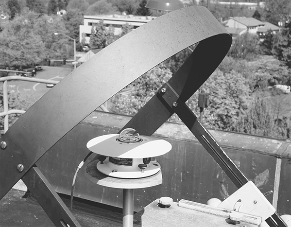
FIGURE 6.3 (See color insert.) The Eppley model SBS shadowband blocks direct sunlight on a clear summer day in Eugene, Oregon. Note that the detector surface is well centered beneath the shadowband. The shadowband blocks a significant part of the brightest region of the clear-day skylight.
Because the fixed shadowband or shade ring can block over 20% of the diffuse irradiance, a correction is needed for the excluded diffuse irradiance. This correction factor for the fixed shadowband or shade ring is a frequent topic in the solar radiation literature. Drummond (1956) developed a geometrical correction for the blocked skylight, assuming an isotropic (uniform) distribution of skylight. This method is applicable for any location on Earth. However, as previously described, diffuse radiation is not uniformly distributed. Papers since Drummond have developed corrections or evaluated correction schemes for the true distribution of skylight for different conditions from overcast to clear skies. Corrections derived for one climate are often not applicable to another because different sky conditions prevail at dissimilar locations.
Kudish and Evseev (2008) recently evaluated four of these correction methods: Drummond (1956), LeBaron, Michalsky, and Perez (1990), Battles, Alados-Arbodelas, and Olmo (1995), and Muneer and Zhang (2002). Gueymard and Myers (2009) pointed out, however, that this evaluation is invalid because the data used for establishing the “true diffuse values” employed the subtraction method to calculate diffuse values from GHI and direct horizontal values. Diffuse values obtained by the subtraction method contain significant systematic errors due in large part to the angular response (or cosine) errors of the unshaded pyranometer and do not have the accuracy to establish a reliable diffuse value. Most—maybe all—of the correction methods that have been developed used the subtraction method for diffuse values as the standard for comparison. It is clear that more research is needed to establish a more reliable shadowband adjustment factor; however, fixed shadowband DHI values will always have high uncertainties associated with mathematical shadowband corrections. Our recommendation, as will become clear, is to measure diffuse with a tracking disk such as the one shown in Figure 6.4.

FIGURE 6.4 (See color insert.) An example of a shaded-disk measurement of DHI. The arm holds disks that shade each of three black-and-white pyranometers.
6.2.2 CALCULATED DIFFUSE IRRADIANCE VERSUS SHADE DISK DIFFUSE
DHI can be calculated from GHI and DNI data. The difficulty with this approach stems from using the difference of the global horizontal and direct beam as the best estimate of diffuse horizontal irradiance, that is,
where sza is the solar zenith angle. A very good measurement of the DNI has a 95% uncertainty of around +/–2%, and a very good global measurement has a 95% uncertainty of +/–3% or higher because of additional uncertainties associated with thermal offsets and imperfect cosine responses (Stoffel et al., 2010). The uncertainty of calculating diffuse irradiance from GHI and DNI is significant. To illustrate the uncertainty in calculating diffuse in this way, assume a value for DNI and GHI of 1000 Wm–2 each at a solar zenith angle of 30°. The calculated diffuse would be
with an expanded uncertainty of
or a 26% uncertainty in the calculated diffuse using two state-of-the-art measurements.
A vast improvement in uncertainty is possible if the diffuse is, instead, measured with a tracking disk, or ball, shading a pyranometer. The 3% uncertainty of the pyranometer measurement, using this example, would amount to only 4 Wm–2, an improvement of a nearly a factor of 10 in uncertainty. The preferred method to evaluate fixed shadowband corrections, discussed in Section 6.2.1, is to use tracking disk diffuse measurements for the reference irradiance. However, if diffuse measurements are important, efforts should be made to purchase an automatic tracker because diffuse values obtained from fixed shadow bands or by the subtraction method have high uncertainties.
First-class pyranometers often have thermal offsets that are large compared with diffuse irradiance levels. These thermal offsets can be 20% or more of the DHI value. In fact, pyranometers that are uncorrected for thermal offsets have reported diffuse irradiances lower than pure Rayleigh scattering atmospheres (Cess, Qian, and Sun, 2000). Therefore, it is actually preferable to use second-class black-and-white pyranometers with very small thermal offsets, as discussed in Chapter 5, for DHI measurements. High-cost, secondary-standard pyranometers also have minimal thermal offsets and better cosine responses, so the best DHI measurements may be made using secondary-standard pyranometers. A comparison of DHI measurements made using most of the commercially available pyranometers can be found in Michalsky et al. (2003).
6.2.3 ROTATING SHADOWBAND DIFFUSE MEASUREMENTS
The rotating shadowband pyranometer offers a third option for the measurement of diffuse irradiance with at least four suppliers of these types of instruments (see Appendix F). Irradiance, Inc. (http://www.irradiance.com) offers the rotating shadowband radiometer (RSR), which uses a rapidly moving band to alternately expose and shade the diffuser of a silicon photodiode pyranometer with 10 μsec time response. Hundreds of measurements are made during the band sweep with many near, but not quite shading, the diffuser. The measurements made in the solar aureole, the bright disk surrounding the sun, are used to derive an approximation for the excess skylight that is blocked by the band during the shaded measurement. This is akin to a real-time fixed shadowband correction, which was discussed earlier, but uses actual measurements for the correction. The most significant issue with the RSR is that the silicon photodiode sensor has a nonuniform spectral response that significantly underestimates clear-sky diffuse if the instrument is calibrated for global or direct irradiance (see Section 5.4.2). Software to correct this shortcoming is included with the instrument. The effectiveness of this or other correction schemes is under investigation.
Solar Millennium AG (http://www.solarmillennium.de/) offers a very similar device to the RSR just discussed. It offers to acquire and correct the data from the site of the installation and deliver a finished data product to the user, as does Irradiance, Inc.
Yankee Environmental Systems (YES), Inc. (http://www.yesinc.com) makes a seven-channel multifilter rotating shadowband radiometer (MFR–7) and a single detector radiometer (SDR) that makes a spectral and broadband measurement of diffuse irradiance. Until recently, they, too, used a silicon photodiode detector and had to deal with most of the same measurement issues previously discussed for the RSR. YES now offers a single-channel thermopile shadowband radiometer (TSR), and the MFR–7 uses a fast-response thermopile in place of the unfiltered silicon cell (with six additional channels of narrowband wavelength measurements). The performance of this thermopile device is still under study since this thermopile-based radiometer is a relatively new development.
Prede, Inc. (http://www.prede.com) makes the rotating shadow blade (RSB–100), which works with commercial pyranometers (thermopile or silicon cell versions) to make diffuse and global irradiance measurements. There is little information on the design and measurement performance of this new device.
6.3 Calibration of Diffuse Pyranometers
Michalsky et al. (2007) provide a thorough discussion of the calibration and characterization of pyranometers with the goal of defining a standard for DHI measurements. The preferred, but labor-intensive, method for calibrating any pyranometer is to alternately shade and unshade the pyranometer while measuring the reference DNI with an absolute cavity radiometer. The pyranometer response, which is the inverse of the calibration factor (a multiplier), is then calculated using
where Vx are the voltage readings of the pyranometer unshaded and shaded, and sza is the solar zenith angle at the time of measurement. These calibration measurements should be made when the sun is at a solar zenith angle of 45° ± 3°. The details of performing this calibration procedure are in Michalsky et al. (2007) and are discussed in detail in Chapter 5.
Why calibrate at 45°? If skylight were isotropic (i.e., uniform in all directions), then the diffuse irradiance falling on a horizontal surface could be calculated as
where Rsky is the constant radiance of the isotropic sky. The term sin(θ)dθdϕ comes from spherical geometry (see Figure 6.5), and the cos(θ) term comes from the Lambert cosine law, which states that the irradiance flux on a surface is proportional to the cosine of the angle of incidence. Since sin(θ)cos(θ) = sin(20)/2, it is clear that the largest contribution to the diffuse irradiance is from the annulus of skylight near 45° and falls monotonically and symmetrically to zero at 0° and 90°. This means that the effective angle of incidence for diffuse radiation is 45°, which does not change throughout the day for isotropic skies. Skylight is not isotropic, but contributions from all parts of the sky are such that the effective incident angle for diffuse is never far from the nominal 45° and changes little throughout the day (Michalsky et al., 2007).
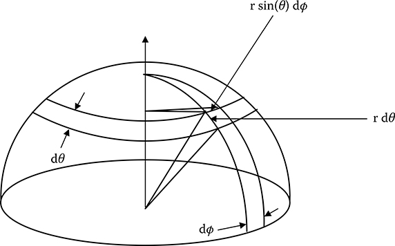
FIGURE 6.5 The geometry used to integrate the radiance distribution of skylight to calculate diffuse horizontal irradiance.
Calibrating pyranometers using the shade–unshade technique eliminates problems with thermal offsets since offsets for the global and diffuse measurements are approximately equal and are eliminated by subtraction of the two components, as can be deduced from Equation 6.4. However, when making diffuse measurements with a single black detector thermopile pyranometer, even if calibrated with the shade–unshade method, a correction must be made to subtract the thermal offset.
Having calibrated a reference pyranometer for diffuse irradiance measurements through the rather onerous procedure previously described, it is possible to calibrate similar pyranometers for diffuse irradiance by simply comparing to this standard under totally overcast, low-cloud conditions. While not strictly isotropic, the sky is uniform enough to yield a reliable calibration. Further, the offset for these cloud-cover conditions will be near zero since the effective sky temperature will be close to the instrument temperature resulting in low values of net infrared (IR) and, consequently, low thermal offsets.
6.4 Value of Accurate Diffuse Measurements
Because there are systematic errors with all pyranometers currently available, the most accurate GHI values can best be obtained from DNI and DHI measurements. As with the example for calculating diffuse from GHI and DNI, the uncertainty of GHI can also be estimated when it comes from DNI and DHI. Under clear-sky conditions with a properly shaded pyranometer used for the diffuse measurement with a +/–3% uncertainty, the calculated global would be
with an uncertainty of
The uncertainty in the GHI is then around +/–2%, which is better than the +/–3% obtainable from most well-maintained GHI measurements. The reason for the improved uncertainty is that most of the irradiance comes from the DNI contribution. Under cloudy conditions, the DNI is zero, and the uncertainty in the GHI is +/–3%, the same as the uncertainty in the DHI.
Because of the relationship between DHI, DNI, and GHI (Equation 4.1), a three-parameter comparison is the best way to validate the accuracy of solar irradiance measurements. If rain or soiling affects the measurements, then the three-component check can check the reliability of the measurements.
Accurate DHI measurements are also essential for the calibration of pyranometers using the summation technique. This method allows the simultaneous calibrations of multiple pyranometers as described in Chapter 5. Diffuse irradiance contributes to all flat-plate solar collectors and is used in all performance calculations. Therefore, any accurate performance analysis requires good DHI measurements. Because DHI is much smaller (typically less than 20%) than the DNI contribution on sunny days, the uncertainty in the DHI contribution is often neglected. However, as the importance of precision measurements increases for analysis of solar system performance, accurate DHI data are becoming indispensable.
Questions
On a clear day, what are two of the several indirect sources (the sun is not a correct answer) of diffuse light on a horizontal surface?
What is the most accurate way to measure DHI?
Why is it possible to measure smaller DHI values with a shaded pyranometer based on a single-black detector than a theoretical pure Rayleigh sky (no clouds or aerosols) would produce?
What are the two sources of measurement error when using a fixed band to measure DHI?
What is the major advantage of the black-and-white pyranometer in measurements of DHI?
On a clear day with some aerosols present, which is likely to be brighter: (1) a point in the sky 90° from the sun in the same vertical plane as the sun and the zenith, or (2) a point near the horizon?
What is the most significant problem with using a photodiode pyranometer for DHI measurements?
Under what circumstances is skylight isotropically distributed during the daylight hours?
References
Battles, F. J., L. Alados-Arbodelas, and F. J. Olmo. 1995. On shadow band correction methods for diffuse irradiance measurements. Solar Energy 54:105–114.
Cess, R. D., T. Qian, and M. Sun. 2000. Consistency tests applied to the measurement of total, direct, and diffuse shortwave radiation at the surface. Journal of Geophysical Research, 105:24,881–24,887. doi: 10.1029/2000JD900402
Drummond, A. J. 1956. On the measurement of sky radiation. Archives for Meteorology, Geophysics, and Bioclimatology-Series B: Climatology, Environmental Meteorology, Radiation Research. 7:413–436.
Gueymard, C. A. and D. R. Myers. 2009. Evaluation of conventional and high-performance routine solar radiation measurements for improved solar resource, climatological trends, and radiative forcing. Solar Energy 83: 171–185.
Kudish, A. I. and E. G. Evseev. 2008. The assessment of four different correction models applied to the diffuse radiation measured with a shadow ring using global and normal beam radiation measurements for Beer Sheva, Israel. Solar Energy 82: 144–156.
LeBaron, B. A., J. J. Michalsky, and R. Perez. 1990. A new simplified procedure for correcting shadow band data for all sky conditions. Solar Energy 44:249–256.
Michalsky, J. J., R. Dolce, E. G. Dutton, M. Haeffelin, G. Major, J. A. Schlemmer, D. W. Slater, J. R. Hickey, W. Q. Jeffries, A. Los, D. Mathias, L. J. B. McArthur, R. Philipona, I. Reda, and T. Stoffel. 2003. Results from the first ARM diffuse horizontal shortwave irradiance comparison. Journal of Geophysical Research, 112:D16111, 10 pp. doi: 10.1029/2007JD008651
Michalsky, J. J., C. Gueymard, P. Kiedron, L. J. B. McArthur, R. Philipona, and T. Stoffel. 2007. A proposed working standard for the measurement of diffuse horizontal shortwave irradiance. J. Geophys. Res. 112:D16112. doi: 10.1029/2007JD008651
Moon, P. and D. Spencer. 1942. Illumination from a non-uniform sky. Illuminating Engineering 37:707–726.
Muneer, T. and X. Zhang. 2002. A new method for correcting shadow band diffuse irradiance data. Journal of Solar Energy Engineering 124:34–43.
Myers, D. R., K. A. Emery, and T. L. Stoffel. 1989. Uncertainty estimates for global solar irradiance measurements used to evaluate PV device performance. Solar Cells 27:455–464.
Stoffel, T., D. Renné, D. Myers, S. Wilcox, M. Sengupta, R. George, and C. Turchi. 2010. Concentrating solar power: Best practices handbook for the collection and use of solar resource data. NREL/TP–550–47465. Golden, CO: National Renewable Energy Laboratory. http://www.nrel.gov/docs/fy10osti/47465.pdf