
An object-oriented program's runtime structure often bears little resemblance to its code structure. The code structure is frozen at compile-time; it consists of classes in fixed inheritance relationships. A program's runtime structure consists of rapidly changing networks of communicating objects. In fact, the two structures are largely independent. Trying to [understand] one from the other is like trying to understand the dynamism of living ecosystems from the static taxonomy of plants and animals, and vice versa.
—E. Gamma, R. Helms, R. Johnson, and J. Vlissides [Gamma 95]
In Chapter 2, we stated that software architecture describes elements of a system and the relations among them. We also emphasized that every system has many kinds of elements and that different architectural structures are useful, even necessary, to present a complete picture of the architecture of a system. Each structure concentrates on one aspect of the architecture.
This chapter will present a case study of an architecture designed by engineering and specifying three specific architectural structures: module decomposition, uses, and process. We will see how these structures complement each other to provide a complete picture of how the system works, and we will see how certain qualities of the system are affected by each one. Table 3.1 summarizes the three structures we will discuss.

Figure 3.1 shows the ABC as it pertains to the A-7E avionics system described in this chapter. The system was constructed beginning in 1977 for the naval aviators who flew the A-7E aircraft and was paid for by the U.S. Navy. The developing organization was the software engineering group at the U.S. Naval Research Laboratory. The developers were creating the software to test their belief that certain software engineering strategies (in this case, information hiding and cooperating sequential processes) were appropriate for high-performance embedded real-time systems.

The architects included one of the authors of this book and one of the leaders in the development of software engineering principles, but the architects had little experience in the avionics domain, although they did have access to other avionics systems and to experts in avionics. There was no compiler available for the target platform.
We will start by explaining the application, what the system does, which qualities were important to achieve, and the software's role in performing the system's task.
Figure 3.2 shows the A-7E Corsair II. It is a single-seat, carrier-based attack aircraft used by the U.S. Navy throughout the 1960s, 1970s, and 1980s. An earlier version, the A-7C, was among the very first production aircraft in the world to be equipped with an onboard computer to help the pilot with navigation and “weapon delivery” (the military euphemism for attacking a ground target).
Figure 3.2. An A-7E Corsair II.

Used with permission and under copyright of Squadron/Signal Publications, Inc.
The A-7E's onboard computer is a small, special-purpose IBM machine for which no compiler exists; programming is in assembly language only. The computer has special registers connected to analog-to-digital and digital-to-analog converters that let it receive and send data to almost two dozen devices in the aircraft's avionics suite.
In broad terms, the A-7E software is responsible for reading sensors and updating cockpit displays that help the pilot drop weapons on a target. The A-7E software does not actually fly the aircraft, as more modern avionics systems do.
The following are the primary sensors the software reads and manages:
• An air probe that measures barometric pressure and air speed.
• A forward-looking radar that can be aimed in azimuth and elevation and returns the straight-line range to the point on the ground at which it is pointed.
• A Doppler radar that reports ground speed and drift angle (the difference between the direction in which the aircraft's nose is pointed and the direction in which it is moving over the ground).
• An inertial measurement set (IMS) that reports accelerations along each of three orthogonal axes. The software must read these accelerations in a timely manner and integrate them over time to derive velocities, and it must integrate the velocities over time to derive the aircraft's current position in the physical world. It also must manage the alignment and compensate for the drift of the axes to keep them pointed north, east, and vertical, respectively, so that the measurements accurately correspond to the aircraft's frame of reference.
• An interface to the aircraft carrier's inertial measurement system, through which the aircraft can compute its current position while on board a ship.
• Sensors that report which of the A-7E's six underwing bomb racks hold weapons and which of more than 100 kinds of weapons in the aircraft's repertoire they are. The software stores large tables of the parameters for each weapon type, which let it compute how that weapon moves through the atmosphere in a free-fall ballistic trajectory.
• A radar altimeter that measures the distance to the ground.
The cockpit display devices managed by the software include some that are display only and some by which the pilot communicates with the software, as follows:
• A map display that always shows the aircraft's current location by moving a back-lit filmstrip as the aircraft travels. The pilot can choose the map's orientation so that the top corresponds either to the current heading or to true north.
• A heads-up display—a device that projects digital and iconographic information on a clear window between the pilot and the windscreen. Since the pilot's head position is assumed fixed and known, the display can be used to overlay information about the real world, such as the position of the target or a line showing the aircraft's direction of travel.
• A keypad and a trio of small alphanumeric display windows. With the keypad, the pilot can request approximately a hundred kinds of digital information from the computer. A bank of switches on the computer control panel allows the pilot to choose the desired navigation and weapon delivery modes.
• Various lights and dials and an audible signal.
The pilot communicates the location of a ground target (or a navigational waypoint) to the software in a number of ways, including the following:
• Keying in its latitude and longitude via the keypad
• Slewing the map using a joystick until its coordinates are under the center crosshairs and then “designating” it by pushing a special button on the control stick
• Aiming the forward-looking radar to the point and designating it
• Slewing a special symbol on the heads-up display until it overlays the point of interest on the ground and then designating it
The software then provides navigational information (direction, distance, time to go) and directional cues on the heads-up display that take the aircraft to the designated location.
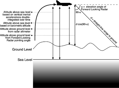
The pilot can choose from over two dozen navigation modes, based on which sensors are most reliable under the conditions of the moment. The software has at least five direct and indirect ways to calculate the aircraft's current altitude, including a trigonometric scheme using the range and elevation angle of the forward-looking radar as components of a triangle (see Figure 3.3). There are more than 20 weapon delivery modes, all demanding in terms of the real-time calculations (repeated 25 times every second) necessary to maintain the A-7E's bombing accuracy.
A-7Es were retired from active duty in the late 1980s, but current-generation fighters feature a heads-up display and weapon delivery and navigation modes that show heavy influence from the Corsair.
The architecture we will present in this chapter is not the architecture for the original software but that for a redesign project launched by Navy software engineers using the A-7E as a demonstration project for their ideas (see the sidebar About the A-7 Project). The qualities that the software system was expected to have included real-time performance and modifiability for expected changes. Specifically, the performance requirements were stated in terms of updates per second of the A7-E's displays and weapon delivery calculations. The modifiability requirements dealt with making changes to the weaponry, the platform, the symbology on the display, and the addition of new input through the keypad.
The architecture for the A-7E avionics system is centered around three architectural structures discussed in Chapter 2:
• Decomposition, a structure of modules
• Uses, a structure of modules
• Process, a structure of components and connectors
We will discuss each in turn.
Unless a program is small enough to be produced by a single programmer, we must think how the work will be divided into units that can be implemented separately and how those modules will interact. The unit of the decomposition structure is, of course, the module. A module may be thought of as defining a group of procedures, some public and some private, plus a set of private data structures. The relation among modules in the decomposition structure is “is-a-submodule-of” or “shares-a-secret-with.”
Prior to 1977, performance was the overriding goal of embedded (as well as most other) systems. The goal of the A-7E designers was to balance performance with modifiability and demonstrate that it was possible to achieve modifiability without compromising performance.
The A-7E module decomposition is based on information hiding. An architectural tactic we will revisit in Chapter 5, information hiding works by encapsulating system details that are likely to change independently in different modules. The interface of a module reveals only those aspects considered unlikely to change; the details hidden by the module interface are the module's secrets.
For instance, if a device such as an aircraft altitude sensor is likely to be replaced over the life of an avionics program, the information-hiding principle makes the details of interacting with that device the secret of one module. The interface to the module provides an abstraction of the sensor, consisting perhaps of a single program that returns the most recent value measured by the sensor, because all replacement sensors probably share this capability. If the sensor is ever replaced, only the internal parts of that module need to change; the rest of the software is unaffected.
Information hiding is enforced by requiring that modules interact only via a defined set of public facilities—their interfaces. Each module provides a set of access procedures, which may be called by any other module in the system. The access procedures provide the only inter-module means for interacting with information encapsulated in a module.
Of course, this is the philosophy underlying object-based design, with a key difference: Whereas objects are created from the physical objects inherent in the application, or conjured up from intuitive insights about the system, information-hiding modules are derived by cataloging the changes to the software that are perceived to be likely over the system's lifetime.
A module may consist of submodules, or it may be considered a single implementation unit. If it contains submodules, a guide to its substructure is provided. The decomposition into submodules and their design is continued until each module is small enough to be discarded and begun again if the programmer assigned to it leaves the project.
Specific goals of module decomposition are as follows:
• Each module's structure should be simple enough to be understood fully.
• It should be possible to change the implementation of one module without knowledge of the implementation of other modules and without affecting the behavior of other modules.
• The ease of making a change in the design should bear a reasonable relationship to the likelihood of the change being needed; it should be possible to make likely changes without changing any module interfaces; less likely changes may involve interface changes but only for modules that are small and not widely used. Only very unlikely changes should require changes in the interfaces of widely used modules.
• It should be possible to make a major software change as a set of independent changes to individual modules (i.e., except for interface changes, programmers changing the individual modules should not need to communicate). If the module interfaces are not revised, it should be possible to run and test any combination of old and new module versions.
The documentation of the decomposition structure is sometimes called a module guide. It defines the responsibilities of each of the modules by stating the design decisions that will be encapsulated by it. Its purpose is to avoid duplication and gaps, to achieve separation of concerns, and, most of all, to help a maintainer find out which modules are affected by a problem report or change request.
The guide states the criteria used to assign a particular responsibility to a module and arranges the modules in such a way that we can find the necessary information without searching through unrelated documentation. It reflects the tree structure of the decomposition structure, dividing the system into a small number of modules and treating each one in the same way until all of them are quite small. Each nonleaf node in the tree represents a module composed of the modules represented by its descendants. The guide does not describe any runtime relationship among the modules: It doesn't talk about how modules interact with each other while the system is executing; rather, it simply describes a design-time relationship among the implementation units that constitute the design phase of a project.
Applying this principle is not always easy. It is an attempt to lower the expected cost of software by anticipating likely changes. Such estimates are necessarily based on experience, knowledge of the application area, and an understanding of hardware and software technology. Because a designer might not have had all of the relevant experience, formal evaluation procedures were used that were designed to take advantage of the experience of others. Table 3.2 summarizes the role of the module structure in the A-7E architecture.

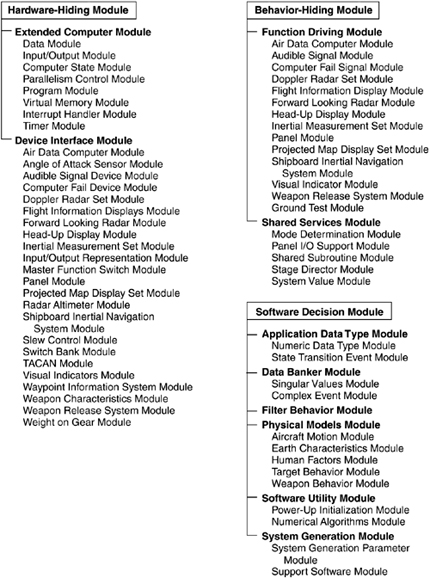
To describe the A-7E module decomposition structure, and to give an example of how a module structure is documented, we provide the following excerpts from the A-7E software module guide. The decomposition tree is described beginning with the three highest-level modules. These are motivated by the observation that, in systems like the A-7E, changes tend to come from three areas: the hardware with which the software must interact, the required externally visible behavior of the system, and a decision solely under the jurisdiction of a project's software designer.
Hardware-Hiding Module. The Hardware-Hiding Module includes the procedures that need to be changed if any part of the hardware is replaced by a new unit with a different hardware/software interface but with the same general capabilities. This module implements virtual hardware, or a set of abstract devices that are used by the rest of the software. The primary secrets of this module are the hardware/software interfaces. The secondary secrets of this module are the data structures and algorithms used to implement the virtual hardware. One of the submodules of the Hardware-Hiding Module is the Extended Computer Module that hides the details of the processor.
Behavior-Hiding Module. The Behavior-Hiding Module includes procedures that need to be changed if there are changes in requirements affecting the required behavior. Those requirements are the primary secret of this module. These procedures determine the values to be sent to the virtual output devices provided by the Hardware-Hiding Module.
Software Decision Module. The Software Decision Module hides software design decisions that are based on mathematical theorems, physical facts, and programming considerations such as algorithmic efficiency and accuracy. The secrets of this module are not described in the requirements document. This module differs from the other modules in that both the secrets and the interfaces are determined by software designers. Changes in these modules are more likely to be motivated by a desire to improve performance or accuracy than by externally imposed changes.
The module guide goes on to explain how conflicts among these categories (e.g., is a required algorithm part of the behavior or a software decision?) are arbitrated by a complete and unambiguous requirements specification and then provides the second-level decomposition. The following sections describe how the Software Decision Module is decomposed.
Application Data Type Module— The Application Data Type Module supplements the data types provided by the Extended Computer Module with data types that are useful for avionics applications and do not require a computer-dependent implementation. Examples of types include distance (useful for altitude), time intervals, and angles (useful for latitude and longitude). These data types are implemented using the basic numeric data types provided by the Extended Computer; variables of those types are used just as if the types were built into the Extended Computer.
The secrets of the Application Data Type Module are the data representation used in the variables and the procedures used to implement operations on those variables. Units of measurement (such as feet, seconds, or radians) are part of the representation and are hidden. Where necessary, the modules provide conversion operators that deliver or accept real values in specified units.
Data Banker Module— Most data are produced by one module and consumed by another. In most cases, the consumers should receive a value that is as up to date as practical. The time at which a datum should be recalculated is determined both by properties of its consumer (e.g., accuracy requirements) and by properties of its producer (e.g., cost of calculation, rate of change of value). The Data Banker Module acts as a “middleman” and determines when new values for these data are computed.
The Data Banker Module obtains values from producer procedures; consumer procedures obtain data from Data Banker access procedures. The producer and consumers of a particular datum can be written without knowing when a stored value is updated. In most cases, neither the producer nor the consumer need be modified if the updating policy changes.
The Data Banker provides values for all data that report on the internal state of a module or on the state of the aircraft. The Data Banker also signals events involving changes in the values that it supplies. The Data Banker is used as long as consumer and producer are separate modules, even when they are both submodules of a larger module. The Data Banker is not used if consumers require specific members of the sequence of values computed by the producer or if a produced value is solely a function of the values of input parameters given to the producing procedure, such as sin(x).[1]
The choice among updating policies should be based on the consumers' accuracy requirements, how often consumers require the value, the maximum wait that consumers can accept, how rapidly the value changes, and the cost of producing a new value. This information is part of the specification given to the implementor of the Data Banker Module.
Filter Behavior Module—The Filter Behavior Module contains digital models of physical filters. They can be used by other procedures to filter potentially noisy data. The primary secrets of this module are the models used for the estimation of values based on sample values and error estimates. The secondary secrets are the computer algorithms and data structures used to implement those models.
Physical Models Module—The software requires estimates of quantities that cannot be measured directly but can be computed from observables using mathematical models. An example is the time that a ballistic weapon will take to strike the ground. The primary secrets of the Physical Models Module are the models; the secondary secrets are the computer implementations of those models.
Software Utility Module—The Software Utility Module contains those utility routines that would otherwise have to be written by more than one other programmer. The routines include mathematical functions, resource monitors, and procedures that signal when all modules have completed their power-up initialization. The secrets of the module are the data structures and algorithms used to implement the procedures.
System Generation Module—The primary secrets of the System Generation Module are decisions that are postponed until system generation time. These include the values of system-generation parameters and the choice among alternative implementations of a module. The secondary secrets of the System Generation Module are the method used to generate a machine-executable form of the code and the representation of the postponed decisions. The procedures in this module do not run on the onboard computer; they run on the computer used to generate the code for the onboard system.
The module guide describes a third- (and in some cases a fourth-) level decomposition, but that has been omitted here. Figure 3.4 shows the decomposition structure of the A-7E architecture down to the third level. Notice that many of the Device Interface modules have the same names as Function Driver modules. The difference is that the Device Interface modules are programmed with knowledge of how the software interfaces with the devices; the Function Driver modules are programmed with the knowledge of values required to be computed and sent to those devices. This suggests another architectural relationship that we will explore shortly: how the software in these modules cooperates to accomplish work.
But the module decomposition view is not yet complete. Recall from Chapter 2 our definition of architecture as including the behavioral specification for each of the elements. Carefully designed language-independent interfaces are crucial for maintaining portability and achieving interoperability. Here, each module must have an interface specified for it. Chapter 9 discusses documentation for software interfaces.
In the previous chapter, we remarked that architectures serve as the blueprint for the developing project as well as for the software. In the case of the A-7E architecture, this second-level module decomposition structure became enshrined in many ways: Design documentation, online configuration-controlled files, test plans, programming teams, review procedures, and project schedule and milestones all used it as their unit of reference.
The second major structure of interest in the A-7E architecture is the uses structure. The decomposition structure carries no information about runtime execution of the software; you might make an educated guess as to how two procedures in different modules interact at runtime, but this information is not in fact in the module decomposition. Rather, the uses structure supplies the authoritative picture of how the software interacts.
The concept behind the uses structure is the uses relation. Procedure A is said to use procedure B if a correctly functioning procedure B must be present in order for procedure A to meet its requirements. In practice this relation is similar to but not quite the same as the calls relation. Procedure A usually calls procedure B because it uses it. However, here are two cases where uses and calls are different:
- Procedure A is simply required to call procedure B in its specification, but the future computation performed by A will not depend on what B does. Procedure B must be present in order for procedure A to work, but it need not be correct. A calls, but does not use, B. B might be an error handler, for example.
- Procedure B performs its function without being called by procedure A, but A uses the results. The results might be an updated data store that B leaves behind. Or B might be an interrupt handler that A assumes exists and functions correctly. A uses, but does not call, B.
The uses relation allows rapid identification of functional subsets. If you know that procedure A needs to be in the subset, you also know that every procedure that A uses must also be there. The transitive closure of this relation defines the subset. It therefore pays to engineer this structure, to impose a discipline on it, so that every subset needn't consist of the entire system. This means specifying an allowed-to-use structure for programmers. After implementation is complete, the actual uses can be cataloged.
The unit of the uses (or allowed-to-use) structure is the access procedure. By dictating what procedures are allowed to use which other procedures (and, by implication, what procedures are not allowed to be used by which other procedures), the uses structure is defined.
Although the unit of the uses structure is a procedure, in practice all of the procedures of a module may share usage restrictions. Hence, the name of a module might appear in the uses structure; if so, it is shorthand for all of the access procedures in that module.
The uses (allowed-to-use) structure is conceptually documented with a binary matrix; each row and column lists every procedure in the system. Thus, if element (m,n) is true, then procedure m uses (is allowed to use) procedure n. In practice, this is too cumbersome, and a shorthand was introduced in which rules for whole modules (as opposed to individual procedures within each module) were adopted.
Table 3.3 summarizes the role of the uses structure in the A-7E software architecture.

Recall that the uses structure is first documented in a specification showing the allowed-to-use relation; actual uses are extracted after implementation. The allowed-to-use specification for the A-7E architecture is a seven-page table of which Table 3.4 is a short excerpt. The two-character preface refers to the second-level modules. The names to the right of the period refer to submodule names that we have mostly omitted from this chapter.

Notice the pattern that emerges:
• No procedure in the Extended Computer Module is allowed to use a procedure in any other module, but all other modules are allowed to use (portions of) it.
• Procedures in the Application Data Type Module are allowed to use only procedures in the Extended Computer Module and nothing else.
• Procedures in the Device Interface Module (at least the part shown) are allowed to use only Extended Computer, Application Data Type, and Physical Models procedures.
• Function Driver and Shared Services procedures can use Data Banker, Extended Computer, Application Data Type, and Device Interface procedures.
• No procedure can use any procedure in the Function Driver Module.
• Only a Function Driver procedure can use a Shared Services procedure.
What we have is a picture of a system partitioned into layers. The Extended Computer Module is the bottommost layer, and the Application Data Type Module is built right on top of it. The two form a virtual machine in which a procedure at a particular level is allowed to use a procedure at the same or any lower level.
At the high end of the layering come the Function Driver and Shared Services modules, which have the freedom to use a wide variety of system facilities to do their jobs. In the middle layers lie the Physical Models, Filter Behavior, and Data Banker modules. The Software Utilities reside in parallel with this structure and are allowed to use anything (except the Function Drivers) necessary to accomplish their individual tasks.
Layered architectures are a well-known architectural pattern and occur in many of the case studies in this book. Layering emerges from the uses structure, but is not a substitute for it as layering does not show what subsets are possible. This is the point of the uses structure—a particular Function Driver Module will use a particular set of Shared Services, Data Banker, Physical Models, Device Interface, Application Data Type, and Extended Computer operations. The used Shared Services in turn use their own set of lower-level procedures, and so forth. The complete set of procedures derived in this manner constitutes a subset.
The allowed-to-use structure also provides an image of how the procedures of modules interact at runtime to accomplish tasks. Each Function Driver procedure controls the output value associated with one output device, such as the position of a displayed symbol. In general, a Function Driver procedure retrieves data (via Data Banker procedures) from data producers, applies rules for computing the correct value of its assigned output, and sends that value to the device by calling the appropriate Device Interface procedure. Data may come from one of the following:
• Device Interface procedures about the state of the world with which the software interfaces
• Physical Models procedures that compute predictive measures about the outside world (such as where a bomb will strike the earth if released now, given the aircraft's current position and velocity)
• Shared Services procedures about the current mode, the trustworthiness of current sensor readings, or what panel operations the pilot has requested
Once the allowed-to-use structure is designed, implementors know what interfaces they need to be familiar with in order to do their work. After implementation is complete, the actual uses structure can be documented so that subsets can be fielded. The ability to deploy a subset of a system is an important part of the Evolutionary Delivery Life Cycle (see Chapter 7, Designing the Architecture). When budgets are cut (or overrun) and schedules slip, delivering a subset is often the best way to put a positive face on a bad situation. It is probably the case that more subsets would be delivered (instead of nothing at all) if the architectural structure necessary to achieve them—the uses structure—had been carefully designed.
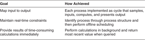
The third structure of architectural importance to the A-7E is the process structure. Even though the underlying aircraft computer is a uniprocessor, the Extended Computer Module presents a virtual programming interface that features multiprocessing capabilities. This was to plan for if and when the A-7E computer was replaced with an actual multi-processor. Hence, the software was implemented as a set of cooperating sequential processes that synchronize with each other to cooperatively use shared resources. The set was arranged using offline (pre-runtime) scheduling to produce a single executable thread that is then loaded onto the host computer.
A process is a set of programming steps that are repeated in response to a triggering event or to a timing constraint. It has its own thread of control, and it can suspend itself by waiting for an event (usually by invoking one of the event-signaling programs on a module's interface).
Processes are written for two purposes in the A-7E. The first is for the function drivers to compute the output values of the avionics software. They are required to run periodically (e.g., to continuously update a symbol position on the heads-up display) or in response to some triggering event (e.g., when the pilot presses the weapon release button). It is natural to implement these as processes. Conceptually, function driver processes are structured as follows:
• Periodic process: do every 40 milliseconds
– Call other modules' access procedures to gather the values of all relevant inputs
– Calculate the resulting output value
– Call the appropriate Device Interface procedure to send the output value to the outside world
• End periodic process
• Demand process
– Await triggering event
– Calculate the resulting output outcome
– Call the appropriate Device Interface procedure to trigger the action in the outside world
• End demand process
Processes also occur, although less frequently, as a way to implement certain access procedures. If the value returned by an access procedure is expensive to compute, a programmer might meet the timing requirements by continuously computing the value in the background and simply returning the most recent value immediately when the access procedure is called. For example,
• Process: do every 100 milliseconds
– Gather inputs to compute value
– Compute value
– Store in variable most_recent
• End process
• Procedure get_value(p1)
– p1 := most_recent.
– return
• End procedure
The process structure, then, consists of the set of processes in the software. The relation it contains is “synchronizes-with,” which is based on events that one process signals and one or more processes await. This relation is used as the primary input to the scheduling activity, which includes deadlock avoidance.
The offline scheduling techniques used in the A-7E software are beyond the scope of this treatment, but they avoid the overhead of a runtime scheduler, and they would not have been possible without the information contained in the process structure. The process structure also allows an optimization trick: merging two otherwise unrelated processes, which makes scheduling easier in many circumstances and avoids the overhead of context switching when one process suspends and another resumes. This technique is invisible to programmers, occurring automatically during system construction. Table 3.5 summarizes the role of the process structure in the A-7E architecture.
The process structure emerged after the other structures had been designed. Function Driver procedures were implemented as processes. Other processes computed time-consuming calculations in the background so that a value would always be available.
Two kinds of information were captured in the process structure. The first documented what procedures were included in the body of each process. This gave a picture of the threads that ran through the system and also told the implementors which procedures must be coded to be re-entrant (i.e., able to carry two or more threads of control simultaneously) by using protected data stores or mutual exclusion. It also gave designers early insight into which procedures were going to be invoked most often, suggesting areas where optimization would pay off.
The second kind of information in the process structure documented which processes (or sequential segments of process threads) could not execute simultaneously. The actual regions of mutual exclusion were not finalized until the processes were completely coded, but the early “excludes” relation among processes let the scheduling team understand some of the quantitative requirements of the offline scheduler and start planning on areas where automation would be most helpful.
This chapter described the architecture of a highly capable avionics system in terms of three related but quite different structures. A module decomposition structure describes design-time relations among its components, which are implementation units that can be assigned to teams. A uses structure describes runtime usage relations among its components, which are procedures in modules. From it, a picture of a layered architecture emerges. The process structure describes the parallelism of the system and is the basis for assignment for the physical hardware.
It is critical to design each structure correctly because each is the key to a different quality attribute: ease of change, ease of extracting a subset, and increased parallelism and performance. It is also critical to document each structure completely because the information about each is duplicated in no other place.
Even though the structures are orthogonal, they are related, in that modules contain procedures, which use each other and are strung together in processes. Other architectural structures could have been specified for this system. One, a data flow view (a component-and-connector view additional to those introduced in Chapter 2), would have looked something like the one in Figure 3.5. All data comes from the external world via the Device Interface modules and works its way through computation and storage modules to the Function Driver modules, which compute output values to send back to the devices. The A-7E designers never thought data flow views were useful—what quality attribute do they help achieve that the others do not?—but other designers might feel different. The point—and the lesson—about architectural views is that they should enhance understanding of and intellectual control over the system and its attributes. If a view meets these conditions, it is probably one you will want to pay attention to.

We also presented the architecture in terms of the qualities the designers wished to achieve: changeability and understandability. This leads us to the thesis that we explore in the next two chapters: Architectures reflect a set of desired qualities.
The A7-E avionics project has been documented in [Parnas 85a]. The data collected about changes to the system was analyzed and described in [Hager 91] and [Hager 89]. Much of the material about the module structure was taken from the A-7E module guide, which was written by Kathryn Britton and David Parnas [Britton 81].
1. Suppose that a version of the A-7E software were to be developed for installation on a flight trainer version of the aircraft. This aircraft would carry no weapons, but it would teach pilots how to navigate using the onboard avionics. What structures of the architecture would have to change, and how?
2. Chapter 7 will discuss using the architecture as a basis for incremental development: starting small and growing the system but having a working subset at all times. Propose the smallest subset of the A-7E software that still does something (correctly, in accordance with requirements) observable by the pilot. (A good candidate is displaying a value, such as current heading on some cockpit display.) Which modules do you need and which can you do without? Now propose three incremental additions to that subset and specify the development plan (i.e., which modules you need) for those.
3. Suppose that monitors were added to ensure that correct values were being stored in the Data Banker and computed by the Function Drivers. If the monitors detected a disparity between the stored or computed values and what they computed as the correct values, they would signal an error. Show how each of the A-7E's architectural structures would change to accommodate this design. If you add modules, state the information-hiding criteria for placing them in the module hierarchy.