Completing and Verifying IPsec
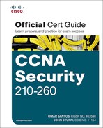
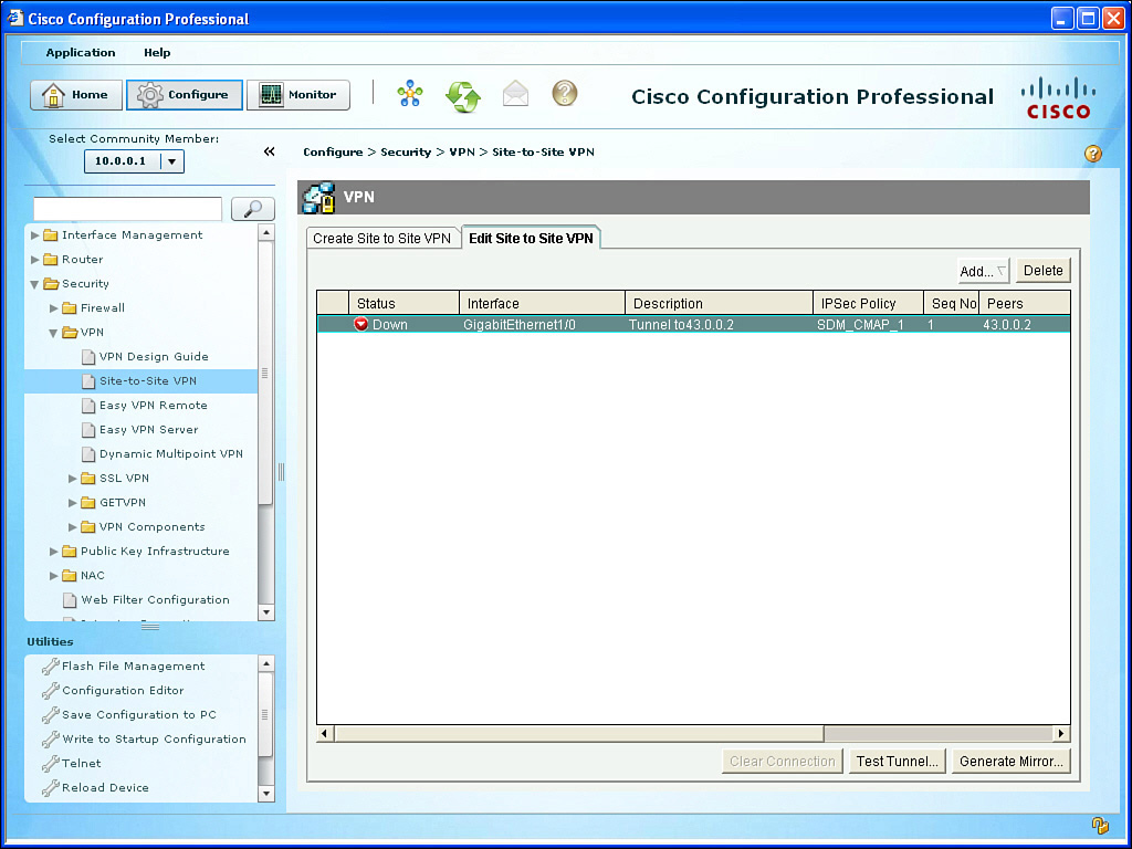
When you click Finish, the CCP shows you the status of the VPN tunnel, as shown in Figure 6-15. The reason the tunnel is down is because the other side is not yet configured.
To configure R2, we could select R2 from within CCP and follow the same process. A shortcut that CCP has provided is the ability to use the Generate Mirror button from R1’s CCP, and then modify and apply that mirror image of the VPN-related configuration to R2. Figure 6-16 shows the result of clicking the Generate Mirror button.

We could then take this file, edit it, and apply it to R2. Example 6-2 shows an edited file that is appropriate for R2.
Example 6-2 Edited Mirrored VPN Configuration Appropriate for R2
crypto isakmp policy 2
authentication pre-share
encr aes 128
hash md5
group 2
lifetime 21600
exit
crypto isakmp key cisco123 address 23.0.0.1
crypto ipsec transform-set MY-SET esp-sha-hmac esp-aes 256
mode tunnel
exit
ip access-list extended SDM_1
permit ip 172.16.0.0 0.0.0.255 10.0.0.0 0.0.0.255
exit
crypto map SDM_CMAP_1 1 ipsec-isakmp
match address SDM_1
set transform-set MY-SET
set peer 23.0.0.1
exit
interface g1/0
crypto map SDM_CMAP_1
end
If you are using CCP and apply this directly to the CLI of R2, be sure to refresh or redis-cover R2 via CCP to reflect the changes. Saving the changes to NVRAM is also recommended after a working solution has been implemented. After generating some traffic from a device on the 10.0.0.0/24 network that is destined for 172.16.0.0/24, the outbound traffic on R1 should trigger encryption, which triggers IKE Phase 1 and Phase 2 to build their tunnels and then begin forwarding the traffic. The successful ping of a device in the 10.0.0.0/24 network to a device in the 172.16.0.0 network, along with the status being shown from CCP, confirms that the VPN tunnel is working, as shown in Figure 6-17.

Subsequent user packets use the newly formed IKE Phase 2 (IPsec) tunnel for the lifetime of that tunnel. From the command line, you could use the following to verify the IPsec, as well, as shown in Example 6-3.
Example 6-3 Verifying the IPsec VPN from the CLI
! Verify the IKE Phase 1 policies in place on the router
R1# show crypto isakmp policy
Global IKE policy
Protection suite of priority 2
encryption algorithm: AES - Advanced Encryption Standard (128 bit keys).
hash algorithm: Message Digest 5
authentication method: Pre-Shared Key
Diffie-Hellman group: #2 (1024 bit)
lifetime: 21600 seconds, no volume limit
! Show the details of the crypto map, and where it is applied, showing
! the contents of the IKE Phase 2 transform sets, learning the ACLs
! involved for the VPN, who the current peer is, and more.
R1# show crypto map
Crypto Map "SDM_CMAP_1" 1 ipsec-isakmp
Description: Tunnel to43.0.0.2
Peer = 43.0.0.2
Extended IP access list 100
access-list 100 permit ip 10.0.0.0 0.0.0.255 172.16.0.0 0.0.0.255
Current peer: 43.0.0.2
Security association lifetime: 4608000 kilobytes/3600 seconds
Responder-Only (Y/N): N
PFS (Y/N): N
Transform sets={
MY-SET: { esp-256-aes esp-sha-hmac } ,
}
Interfaces using crypto map SDM_CMAP_1:
GigabitEthernet1/0
! See the details for the IKE Phase 1 tunnel that is in place
R1# show crypto isakmp sa detail
Codes: C - IKE configuration mode, D - Dead Peer Detection
K - Keepalives, N - NAT-traversal
T - cTCP encapsulation, X - IKE Extended Authentication
psk - Preshared key, rsig - RSA signature
renc - RSA encryption
IPv4 Crypto ISAKMP SA
C-id Local Remote I-VRF Status Encr Hash Auth DH Lifetime Cap.
1001 23.0.0.1 43.0.0.2 ACTIVE aes md5 psk 2 00:04:05
Engine-id:Conn-id= SW:1
! See the details for the IKE Phase 2 tunnels that are in place. There is
! one inbound Security Association (SA) and one outbound. They both have
! different SA numbers used for tracking these sessions.
! ESP is used, and it provides all the services desirable from IPsec.
! The other option is Authentication Header (AH) which isn't used because
! it doesn't support any encryption algorithms.
R1# show crypto ipsec sa
<Note: less relevant content removed>
interface: GigabitEthernet1/0
Crypto map tag: SDM_CMAP_1, local addr 23.0.0.1
! Shows what traffic is being encrypted. All IP traffic between
! 10.0.0.0/24 and 172.16.0.0/24
local ident (addr/mask/prot/port): (10.0.0.0/255.255.255.0/0/0)
remote ident (addr/mask/prot/port): (172.16.0.0/255.255.255.0/0/0)
! IKE Phase 1 uses UDP port 500 to negotiate and set up the IKE Phase 1
! tunnel
current_peer 43.0.0.2 port 500
#pkts encaps: 29, #pkts encrypt: 29, #pkts digest: 29
#pkts decaps: 29, #pkts decrypt: 29, #pkts verify: 29
! From R1's perspective, the local side is its G1/0, and R2 is at 43.0.0.2
local crypto endpt.: 23.0.0.1, remote crypto endpt.: 43.0.0.2
path mtu 1500, ip mtu 1500, ip mtu idb GigabitEthernet1/0
! An SPI is a Security Parameter Index. It is a fancy way of tracking
! a specific Security Association (SA) between itself and a peer.
! Think of it as a serial number (unique) for each SA.
current outbound spi: 0x48A3CF57(1218694999)
! PFS stands for Perfect Forward Secrecy, and it is the ability for IKE
! Phase 2 to run the DH algorithm again, instead of using the keys
! generated during the DH from IKE Phase 1. This feature is off by
! default for most platforms.
PFS (Y/N): N, DH group: none
! The IPsec or IKE Phase 2 is really two tunnels. There is one for
! traffic from R1 to R2. There is another from R2 to R1. They have
! different SPIs, but together, these two unidirectional tunnels make up
! the "IPsec" tunnel.
! Encapsulating Security Payload (ESP) is the primary method used by IPsec.
! The other option is to use Authentication Header (AH), but it doesn't
! have the ability to encrypt, and isn't often used for that reason. AH
! also breaks when going through Network Address Translation (NAT).
! Here is the inbound SA used by R1 to receive encrypted user packets from
! R2.
inbound esp sas:
spi: 0xE732E3A0(3878871968)
transform: esp-256-aes esp-sha-hmac ,
in use settings ={Tunnel, }
conn id: 1, flow_id: SW:1, sibling_flags 80000046, crypto map:
SDM_CMAP_1
sa timing: remaining key lifetime (k/sec): (4388080/3230)
IV size: 16 bytes
! Here is the built in anti-replay support
replay detection support: Y
Status: ACTIVE
! We aren't using AH, so there are no Security Associations (SAs) for AH.
inbound ah sas:
! Here is the Outbound SA used by R1 to send encrypted user packets to R2.
outbound esp sas:
spi: 0x48A3CF57(1218694999)
transform: esp-256-aes esp-sha-hmac ,
in use settings ={Tunnel, }
conn id: 2, flow_id: SW:2, sibling_flags 80000046, crypto map: SDM_
CMAP_1
sa timing: remaining key lifetime (k/sec): (4388079/3230)
IV size: 16 bytes
replay detection support: Y
Status: ACTIVE
outbound ah sas:
! Another way of seeing that the encryption and decryption is working.
R1# show crypto engine connections active
Crypto Engine Connections
ID Type Algorithm Encrypt Decrypt IP-Address
1 IPsec AES256+SHA 0 29 23.0.0.1
2 IPsec AES256+SHA 29 0 23.0.0.1
1001 IKE MD5+AES 0 0 23.0.0.1