Chapter 2
G1 Type Scheme to JVL Inverse Kinematics
2.1 Introduction
In recent years, there have been numerous investigations in to robot manipulators [30–33], especially the redundant robot manipulators. Compared with the ordinary robot manipulators, the redundant one has more degrees of freedom (DOF) than necessary for position and orientation. It is worth noting that this characteristic improves the kinematic and the dynamic performance of the robot manipulator, such as increasing dexterity, avoiding obstacles and singularities, and optimizing joint velocity, which makes redundant the manipulators widely applied in the field of robotic manipulator control [34]. As one of the central issues in robot control, path tracking refers to making the end-effector move as expected by controlling the joints of robot manipulators. When the end-effector moves at a desired speed, it is often called path tracking control at the velocity level (JVL), which can fit in with the needs of the operators well with two advantages [35, 36]. One is that the high velocity can economize the execution time while the other one is that the low velocity can enhance the objective precision [37]. So the control at the velocity level is suited particularly well to tasks for machining operations, such as cutting and milling [38].
Robot kinematics, which studies the relationships between joint space and cartesian space, is a very effective way to control the robot manipulator and attracts numberous researchers [39–41]. The velocities of all joints play a decisive role in realizing the desired speed of the end-effector. So the most fundamental problem is how to use the kinematic equations to calculate the homologous joint velocities, also called inverse kinematics. However, because most kinematic equations involve complex (inverse) trigonometric functions, the inverse kinematics mapping has no closed-form solutions for most manipulators and animation figures [42]. Conventionally, most researchers exploit pseudoinverse approaches to obtain a simple general-form solution [11, 43]. However, these approaches do not only need a lot of time in calculating the inverse of Jacobian matrix, but also require the Jacobian matrix to be of full rank, which may be far from the reality. Thus various approaches have been presented, investigated, and developed to avoid the calculation of the inverse of Jacobian matrix, such as the quadratic programming (QP) method [44].
Gradient dynamics (GD) [45, 46] is a significant dynamic method that attracts many researchers to investigate and develop it. Now, the GD method is proving to be useful and effective and is widely acknowledged in scientific and engineering fields, thus generalizing such a GD method has become the primary work [44, 47–50]. In this chapter, based on GD method's advantage that it can help find a minimum of a nonnegative objective function effectively, we present and investigate a scheme named G1 type for path tracking in the redundant robot manipulator at the joint-velocity level. Also, in the framework of zeroing-gradient (ZG) method, the G1 type scheme is a special Z0G1 situation that only uses the GD method once. The ZG method is an effective method built by combining ZD presented in Chapter 1 and GD to solve the tracking-control and singularity problems [51, 52].
By exploiting the GD method, this chapter presents and investigates a G1 type scheme in an inverse-free manner at the joint-velocity level. The presented G1 type scheme can solve the inverse kinematics problem effectively but avoids calculating the inverse of Jacobian matrix. Besides, the path-tracking simulations and the physical experiments are conducted to further illustrate the effectiveness, the high accuracy, and the physical realizability of the G1 type scheme.
2.2 Preliminaries and Related Work
For a redundant robot manipulator with ![]() joints, the end-effector pose (or position in this chapter) vector
joints, the end-effector pose (or position in this chapter) vector ![]() can be described by the following equation:
can be described by the following equation:
where ![]() refers to the variables (or angles in this chapter) of the
refers to the variables (or angles in this chapter) of the ![]() joints, and
joints, and ![]() is a differentiable nonlinear function with a known structure and parameters for a given manipulator. Then by differentiating Equation (2.1), the end-effector velocity is
is a differentiable nonlinear function with a known structure and parameters for a given manipulator. Then by differentiating Equation (2.1), the end-effector velocity is
where ![]() refers to the end-effector velocity, and
refers to the end-effector velocity, and ![]() refers to the velocities of all joints. Note that
refers to the velocities of all joints. Note that ![]() is the Jacobian matrix defined as
is the Jacobian matrix defined as ![]() . According to Equation (2.2), for tracking the desired path
. According to Equation (2.2), for tracking the desired path ![]() via the desired speed
via the desired speed ![]() , the velocities of all joints can be obtained by the following equation if
, the velocities of all joints can be obtained by the following equation if ![]() is a square matrix and of full rank:
is a square matrix and of full rank:
If ![]() is rectangular, the velocities of joints may be computed by the following equation of generalized inverse [35]:
is rectangular, the velocities of joints may be computed by the following equation of generalized inverse [35]:
where ![]() denotes the pseudoinverse of Jacobian matrix
denotes the pseudoinverse of Jacobian matrix ![]() . However, the inverse scheme theoretically requires the Jacobian matrix to be of full rank, which, in real world application, may be unavailable sometimes in practice.
. However, the inverse scheme theoretically requires the Jacobian matrix to be of full rank, which, in real world application, may be unavailable sometimes in practice.
2.3 Scheme Formulation
In this section, we generalize the GD method to obtain an inverse-free scheme at the joint-velocity level. By following the GD method, the design procedure of such an inverse-free scheme can be presented detailedly via the following steps.
Firstly, to monitor and control the process of solving the time-varying inverse kinematics problem of redundant manipulators, we define a scalar-valued norm-based energy function according to Equation (2.1):
where ![]() denotes the two-norm of a vector.
denotes the two-norm of a vector.
Secondly, a computational rule is designed to evolve along a descent direction of this energy function until the minimum point is reached. The typical descent direction is the negative gradient of ![]() , that is,
, that is,
Then we combine the aforementioned negative gradient (2.6) and the following GD design formula [45, 46]:
where the design parameter ![]() is used to scale the convergence rate of the GD method.
is used to scale the convergence rate of the GD method.
Finally, we have the following generalized G1 type scheme for solving the time-varying inverse kinematics problem of redundant robot manipulators:
Evidently, scheme (2.8) does not require the Jacobian inversion appearing in (2.3) and (2.4). Since scheme (2.8) is obtained by applying the GD method only once, it is named a G1 type (or Z0G1 type in the ZG framework).
2.4 Computer Simulations
In this section, the corresponding path-tracking simulations (square path tracking and “Z”-shaped-path tracking) are performed on five-link and six-DOF redundant robot manipulators, respectively, to illustrate the effectiveness and the accuracy of the presented G1 type scheme. Note that the design parameter ![]() is used throughout this section.
is used throughout this section.
2.4.1 Square-Path Tracking Task
In the first example, G1 type scheme (2.8) is applied to tracking a square path via a desired velocity. The side length of the square path is 0.8 m, and the path tracking is simulated on a five-link redundant robot manipulator, with an initial state ![]() being
being ![]() rad. The corresponding simulation results are shown in Figures 2.1 through Figure 2.3, which illustrate the effectiveness and high accuracy of the presented G1 type scheme (2.8) for solving the time-varying inverse kinematics of robot manipulators.
rad. The corresponding simulation results are shown in Figures 2.1 through Figure 2.3, which illustrate the effectiveness and high accuracy of the presented G1 type scheme (2.8) for solving the time-varying inverse kinematics of robot manipulators.

Figure 2.1 (a) Motion process and (b) joint-angle profiles of a five-link redundant robot manipulator tracking the desired square path synthesized by the G1 type scheme (2.8).

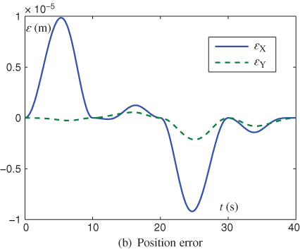
Figure 2.2 (a) Desired path, actual trajectory, and (b) position error of a five-link redundant robot manipulator tracking square path synthesized by a G1 type scheme (2.8).

Figure 2.3 (a) Desired velocity and (b) velocity error of a five-link redundant robot manipulator tracking a square path synthesized by a G1 type scheme (2.8).
Specifically, the results can be seen from Figure 2.1(a) and Figure 2.1(b), from which we can see how the manipulator tracks the desired path with five joints. It is easily found that the actual end-effector trajectory coincides with the desired square path. Figure 2.2(a) and Figure 2.2(b) show us more details about the trajectory. That is, Figure 2.2(a) presents the desired path and the actual trajectory, which illustrates the effectiveness and the accuracy intuitively. The corresponding errors shown in Figure 2.2(b) are all less than ![]() . This implies that the five-link robot manipulator completes the given square-path tracking task well. In addition, the desired velocities and the corresponding velocity errors are shown in Figure 2.3(a) and Figure 2.3(b). We see that the velocity errors are less than
. This implies that the five-link robot manipulator completes the given square-path tracking task well. In addition, the desired velocities and the corresponding velocity errors are shown in Figure 2.3(a) and Figure 2.3(b). We see that the velocity errors are less than ![]() , validating the high accuracy of such an inverse-free type scheme.
, validating the high accuracy of such an inverse-free type scheme.
2.4.2 “Z”-Shaped Path Tracking Task
In the second example, G1 type scheme (2.8) is applied to tracking a “Z”-shaped-path task with the side length being 0.8 m. The corresponding simulation results based on a six-DOF redundant robot manipulator are shown in Figure 2.4 through Figure 2.6, where an initial state ![]() is selected as
is selected as ![]() rad. These results illustrate once more the effectiveness and the high accuracy of the presented G1 type scheme (2.8) for solving the time-varying inverse kinematics of robot manipulators.
rad. These results illustrate once more the effectiveness and the high accuracy of the presented G1 type scheme (2.8) for solving the time-varying inverse kinematics of robot manipulators.
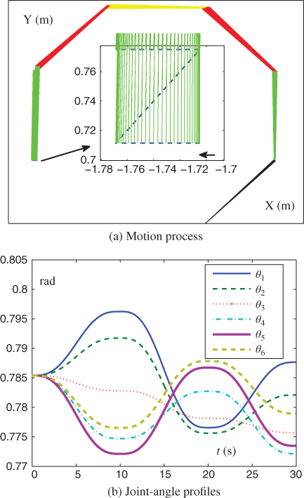
Figure 2.4 Motion process (a) and joint-angle profiles (b) of six-DOF redundant robot manipulator tracking the desired “Z”-shaped path synthesized by a G1 type scheme (2.8).
Specifically, the results can be seen from Figure 2.4(a) and Figure 2.4(b), from which we can see how the manipulator tracks the desired path with six joints. It is easily found that the actual end-effector trajectory coincides well with the desired “Z”-shaped path. In particular, Figure 2.5(a) and Figure 2.5(b) show us more details about the actual trajectory and corresponding errors. These imply that the six-DOF robot manipulator completes the given “Z”-shaped-path tracking task well. Besides, the desired velocities and the corresponding velocity errors are shown in Figure 2.6(a) and Figure 2.6(b). We can find that any directional velocity error is less than ![]() , which validates the high accuracy of such an inverse-free type scheme.
, which validates the high accuracy of such an inverse-free type scheme.

Figure 2.5 (a) Desired path, actual trajectory, and (b) position error of a six-DOF redundant robot manipulator tracking a “Z”-shaped path synthesized by a G1 type scheme (2.8).


Figure 2.6 (a) Desired velocity and (b) velocity error of a six-DOF redundant robot manipulator tracking a “Z”-shaped path synthesized by a G1 type scheme (2.8).
2.5 Physical Experiments
To verify the physical realizability of the presented G1 type scheme (2.8), a six-DOF planar redundant robot manipulator hardware system is developed, investigated, and shown. The whole manipulator system is mainly composed of a robot manipulator, a control cabinet, and a host computer. Specifically, Figure 2.7(a) shows this planar robot hardware system, and Figure 2.7(b) depicts its manipulator-joint structure including a base and an end-effector. Note that the detailed description on the six-DOF planar redundant robot manipulator hardware system will be given in Chapter 6 and thus omitted here.

Figure 2.7 Hardware system (a) of six-DOF planar redundant robot manipulator with its structure platform (b). Source: Zhang et al. 2015. Reproduced from Y. Zhang, L. He, J. Ma et al., Inverse-free scheme of G1 type to velocity-level inverse kinematics of redundant robot manipulators, Figure 3, Proceedings of the Twelfth International Symposium on Neural Networks, pp. 99-108, 2015. ©Springer-Verlag 2015. With kind permission of Springer-Verlag (License Number 3978560065761).
For the experiments, in order to verify the presented G1 type scheme (2.8) at the joint-velocity level, the end-effector is expected to move along a “Z”-shaped path with an initial state ![]() rad and the length of 4.5 cm, and the design parameter
rad and the length of 4.5 cm, and the design parameter ![]() is also set as
is also set as ![]() . The task execution can be seen from Figure 2.8, that is, the end-effector of the manipulator moves smoothly and draws a “Z”-shaped path precisely. Besides, the video of the process takes 24 seconds. Thus, the experiments illustrate well that the presented G1 type scheme (2.8) is effective on the redundant robot manipulator's inverse-free redundancy resolution (or, say, motion planning and control).
. The task execution can be seen from Figure 2.8, that is, the end-effector of the manipulator moves smoothly and draws a “Z”-shaped path precisely. Besides, the video of the process takes 24 seconds. Thus, the experiments illustrate well that the presented G1 type scheme (2.8) is effective on the redundant robot manipulator's inverse-free redundancy resolution (or, say, motion planning and control).
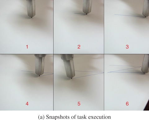
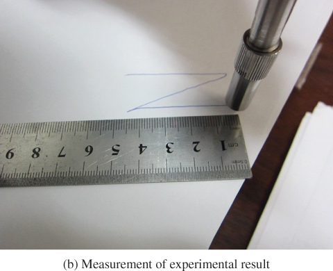
Figure 2.8 “Z”-shaped-path-tracking experiment of six-DOF redundant robot manipulator synthesized by G1 type scheme (2.8) at joint-velocity level. Reproduced from Y. Zhang, L. He, J. Ma et al, Inverse-free scheme of G1 type to velocity-level inverse kinematics of redundant robot manipulators, Figure 4, Proceedings of the Twelfth International Symposium on Neural Networks, pp. 99-108, 2015. ©Springer-Verlag 2015. With kind permission of Springer-Verlag (License Number 3978560065761).
2.6 Chapter Summary
In this chapter, to solve the time-varying inverse kinematics problem for redundant robot manipulators with high efficiency and accuracy, a special type of inverse-free scheme named G1 type scheme has been presented and investigated at the joint-velocity level. This scheme can avoid the Jacobian inversion in traditional pseudoinverse methods that not only costs expensive calculating time but also encounters many difficulties in practice. Besides, the corresponding path-tracking simulations have been performed on five-link and six-DOF redundant robot manipulators using such an inverse-free scheme. The simulation results have illustrated the effectiveness and the accuracy of the aforementioned scheme for solving the time-varying inverse kinematics problem of redundant robot manipulators in an inverse-free manner. In addition, the physical realizability of G1 type scheme has been verified further based on a six-DOF planar redundant robot manipulator hardware system.