
Chapter 14: Load Balancer Configuration and SSL Certificates
In this chapter, we'll be covering the very important task of how to publish our applications that are being hosted inside Kubernetes to the outside world using load balancers and ingress rules. We'll be going over the four main techniques: round-robin DNS, passive external load balancer, active external load balancer, and an integrated load balancer. We'll look at the pros and cons along with an example of each technique, and we'll dive into the best practices for each method. Finally, we will cover how to bring SSL certificates to your cluster.
In this chapter, we're going to cover the following main topics:
- Why do we need an external load balancer to support a Kubernetes cluster?
- Rules for architecting a solution
- Configuring F5 in TCP and HTTP mode
- Configuring HAProxy in TCP and HTTP mode
- Installing and configuring MetalLB
- What is ingress in Kubernetes?
- How to add an SSL certificate to an ingress
Why do we need an external load balancer to support a Kubernetes cluster?
After building a Kubernetes cluster and deploying your first application, the next question that comes up is how do my users access my application? In a traditional enterprise environment, we would deploy our application on a server and then create a DNS record and firewall rules to expose our application to the outside world. Of course, we want our applications to be high availability (HA), so we would usually deploy our application on multiple servers and then create a load balancer that would sit in front of our application's servers. We use a load balancer to distribute traffic across multiple servers and increase the availability of our application by allowing us to add and remove servers from the load balancer as needed.
For Kubernetes clusters, we still have this same problem. We need to deploy our applications across multiple nodes and provide a single point of contact, that is, a virtual IP (VIP) address for our application. Our end users will use it to connect to our application. There are, of course, a few different ways to solve this problem, and in the next section, we will dive into these solutions.
Rules for architecting a solution
This section will cover the four main ways of exposing the applications hosted inside our Kubernetes cluster to the outside world.
Round-robin DNS
The most straightforward load balancing technique is round-robin DNS, which creates a DNS record containing a list of IP addresses instead of just one. For example, let's say you had a three-node cluster with the nodes having IP addresses of 1.1.1.1, 2.2.2.2, and 3.3.3.3, and you want to publish your application, hello-world.example.com. You would create three A records with the name hello-world.example.com with the IP address of each node. By doing this, when a client initially attempts to connect to your application, the client will make a DNS query to their DNS server, which will respond with a list of IP addresses. Most clients will simply attempt to connect to the first IP address in the list, and if that server fails to respond, it will try the following IP address until it runs out of IP addresses. It's essential to note that most DNS servers/providers only allow up to six IP addresses in response.
The following is an example of how requests from different end users follow into the cluster when using round-robin DNS:

Figure 14.1 – Round-robin DNS with a three-node example
Next, let's have a look at the list of pros and cons that this design offers.
The pros are as follows:
- Simplicity – Round-robin DNS is by far the easiest way to load balance an application in your cluster because you already need to create a DNS record for your application, so it's not much work to add multiple IP addresses to that record.
- No additional servers/hardware needed – Because we are just using our DNS infrastructure to be our load balancer, you don't need additional servers/hardware in front of the cluster to balance the load for your cluster.
- Cost – Load balancers are not free; for example, a simple Elastic Load Balancing (ELB) service in AWS can cost around $16/month. Most DNS solutions (such as AWS Route53) are almost free ($0.04/month for 100k requests), and even providers such as CloudFlare are free; you just pay if you want more features.
- Caching – DNS is designed to have multiple caching layers, including all the DNS servers between you and your client, and even your end users' machines have caching built-in. You only have control of the time-to-live (TTL), which tells the DNS server how long to cache a query before requesting a new one. This can help by setting it to as low as 1 second, but now you will put a considerable load on your DNS servers as you effectively turn off caching for that record.
- No actual load balancing – Round-robin DNS is merely just rotating the IP list each time the DNS server is queried. Because of this, factors such as server load, response times, or server uptime are not accounted for when routing traffic to different nodes. This means that if a server crashes or is overloaded, traffic will still be routed to that server until the clients stop trying to use that server and failover to another server. And for some clients, this can take up to 5 minutes to happen.
- Only hard failures count – DNS has no idea about the health of a server if a server has a failure, such as running out of disk space or having a connection problem to a database where the server is still up and responding to requests. So, the request is coming back to the client with 500 errors. The client will still keep using that server even though the next server in the list might be totally fine.
- Updating DNS when nodes change – Whenever a node is added or removed from the cluster, you must manually go into DNS and update all the DNS records for all the applications hosted on that cluster. This can be a significant issue when you start looking at autoscaling clusters. But, you can address this issue by using a service such as ExternalDNS to update DNS as the cluster changes over time dynamically. You can find out more about ExternalDNS by visiting the official documentation at https://github.com/kubernetes-sigs/external-dns.
- No security outside the cluster – Because we are just using DNS to route our traffic, we can't do more advanced features, such as forcing HTTPS, blocking SQL injection attacks, and blocking insecure cryptography.
Note
Most large-scale applications use a type of round-robin DNS called global server load balancing (GSLB), which does bring intelligence into the DNS by doing health checks and responding to requests based on server load, response times, and location. But, this is typically done on top of a load balancing service to provide server-level redundancy, with GSLB providing data center-level redundancy.
It is important to note that round-robin DNS is not recommended due to all the listed cons vastly outweighing the pros.
Passive external load balancer
Sometimes called a dumb load balancer, in this setup, you create a Transmission Control Protocol (TCP) load balancer in front of the cluster. Now, this load balancer doesn't handle any high-level functions of your traffic, that is, routing based on hostname, SSL offloading, caching, and web application firewall (WAF). This is because anything higher than layer 4 in the OSI model is not handled by the load balancer and is provided by the Kubernetes cluster/application. Generally, you would create a node pool with all the worker nodes in this design. Then, you would make a VIP on the load balancer and map it to the node pool.
Note
We'll be covering an HAProxy example in the next section.
The following is an example of how end user traffic is routed through the load balancer and onto the nodes in the cluster:

Figure 14.2 – Example of a load balancer in TCP mode with three nodes
Next, let's have a look at the list of pros and cons that this design offers.
The pros are as follows:
- Low barrier of entry – Most on-premises and cloud environments already have load balancers in place to support other non-Kubernetes applications. So, requesting an additional VIP address and node pool to the existing load balancer can be very easy and add little to no cost to the project.
- Single point of contact of the cluster – Most enterprise load balancers support what's called port 0 mode, which binds all the TCP/UDP ports on the load balancer to the nodes. This can be helpful when exposing non-HTTP applications using the node port. For example, you might publish a MySQL server on port 31001 on all nodes, which becomes available on the VIP using the same port.
- Simple ongoing maintenance – Once the VIP address and node pool have been created, there is no need to update certificates or site names on the load balancer as new applications are added and removed.
- Source IP transparency – With the load balancer in TCP mode, it has two options when the load balancer forwards a request to the server. The first is to leave the source IP address (the end user's IP address) alone and just pass it along the server. The server will process the request and response because the source IP address is the client's IP address. The traffic will not flow back through the load balancer but will be sent directly to the client. This might be okay for some applications, but other applications, such as HTTP(S), MySQL, and SMTP, can have problems with the server's IP address changing during a request.
The other option is what's called NAT mode, which turns the load balancer into the default gateway for the server so that when the request is being sent back to the client, the load balancer can grab the response packet and set the IP addresses back to their original values before sending it on the clients. This, of course, has the downside of your load balancer needing to be in every virtual local area network (VLAN) in your network. Also, East-to-West traffic, that is, traffic going from one node in the cluster to another node in the cluster (assuming they are on the same subnet), will not go back through the load balancer, thereby breaking the source IP address. This also means that all network traffic for the cluster will need to go through the load balancer, including OS patches, management software, and monitoring tools.
- Each cluster needs its load balancer/VIP address – With the load balancer in TCP mode, we can't do any host-based routing; each cluster will need its node pool and VIP address. This, of course, costs you additional IP addresses, and most cloud-based load balancers do not support the addition of IP addresses, so you'll need to create a load balancer for each cluster, which will increase your costs.
- Limited security outside the cluster – We are just passing traffic between the end users and the cluster. We can't do more advanced features such as forcing HTTPS, blocking SQL injection attacks, and blocking insecure cryptography.
- Only basic health checks – With this mode, the load balancer only checks whether the port is open and responding but doesn't check whether the server is healthy.
It is important to remember that there are a number of drawbacks to using a passive load balancer and it should really only be used if you can't use an active external load balancer, which we'll be covering in the next section.
Active external load balancer
In this design, we build a passive external load balancer on top but add intelligence to the chain by moving from layer 4 to 7 instead of blindly forwarding traffic between the clients and servers. The load balancer acts as a virtual server that accepts the request and decodes it, including decrypting the SSL encryption, which allows the load balancer to make decisions on the request, such as routing to different servers/clusters based on the hostname of the request. For example, dev.example.com and staging.example.com share the same public IP address but are routed to two clusters. Or, you can enforce additional security software such as ModSecurity, which can block a wide range of attacks. In the following figure, you can see an example setup with end users' traffic flowing to the DNS A record, to the load balancer, and then finally to the nodes:
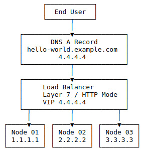
Figure 14.3 – Load balancer in HTTP mode with three nodes example
Next, let's have a look at the list of pros and cons that this design offers.
- Control – With the load balancer in HTTP/layer 7 mode, you have more control over the traffic because the load balancer is making a man-in-the-middle attack between the clients. The server allows the load balancer to inspect and modify the request as it sees fit.
- Wild card certificates – In this mode, we can have a single IP address that can be shared across many different applications. For example, www.example.com and api.example.com might be two separate applications, but they can share the same IP address and wildcard certificate, that is, *.example.com. We can even expand it more by using a multi-domain wildcard SSL, which allows us to have a certificate for *.example.com, *.example.net, and so on. All of these can save money and simplify management, as now we have one certificate for all the applications in one spot.
- Better health checks – In layer 7 mode, the load balancer runs tests such as sending an HTTP request to a known good endpoint to test and verify the server's health. For example, with an ingress-nginx controller, the load balancer can send an HTTP request to port 80 with the /healthz path, which only responds with 200OK if the ingress is up and healthy. If a server is unhealthy, the chances of being gracefully removed from the load balancer are much better.
- No NAT or default gateway needed – Unlike in layer 4 mode, the traffic doesn't need to be force routed through the load balancer as the source IP address will always be the load balancer because the load balancer is repackaging the request.
Note
Most load balancers support a feature called X-Forwarded-For headers, which adds a set of special headers to the HTTP(S) requests that tell the application what the actual IP addresses of the end user are without needing the load balancer to overwrite the source IP address, which can, of course, cause routing issues.
- Additional configuration for new sites – Because the load balancer is SSL offloading, host-based routing, and more, we need to tell the load balancer about sites/applications that we are adding. If we have a certificate covering *.example.com, we add a new application called test.example.net. We have to make sure that our current SSL certificate and rules cover this new domain; if not, we need to update them. This is not usually an issue if all of your applications can be covered under wildcard rules such as *.example.com. But, if you are doing nested domains such as qa1.api.example.com and dev.docs.example.com, these two nested domains will not be covered by the *.example.com wildcard and will require multiple certificates or a multi-domain wildcard SSL that includes *.api.example.com and *.docs.example.com.
- End-to-end SSL requires more work – In layer 4 mode, we are doing the SSL offloading at the ingress-nginx controller level, meaning we only need an SSL certificate in one spot. But, if we move that SSL offloading to the load balancer, we need to decide whether we are okay downgrading to having non-SSL traffic between the load balancer and our cluster, which is the most straightforward option because we just route the backend request to port 80 and call it done. However, if we need to keep the traffic encrypted using SSL, we need to configure an SSL certificate at the ingress-nginx controller and the load balancer. We can now make it easy by default by using the built-in fake certificate with an ingress-nginx controller and configuring the load balancer to ignore the invalid certificate. It's important to review this with your security team to confirm acceptance.
- Speed – DNS and layer 4 are fast because they are simple. Most enterprise load balancers can do layer 4 using specialized chips rather than software, meaning they can operate at very high speeds. For example, A10's 7655S ADC can do 370 Gbps in layer 4 mode but drops to 145 Gbps in layer 7 with SSL. It is important to note that this gap is closing over time because of faster CPUs and better hardware integration.
This approach should be used in environments where the process of updating and configuring the external load balancer is automated because the load balancer will need to be updated as applications are added to your clusters.
Integrated load balancer
The previous solution lacked integration with the Kubernetes clusters management plane, meaning that the management of the cluster and its application is not connected directly to the management of the load balancer and its configuration. This is, of course, addressed by using the load balancer that supports Kubernetes natively. For example, in Amazon's EKS, you can deploy the AWS Load Balancer Controller, which connects the EKS cluster directly to Amazon's load balancer with the controller handling management of the load balancers as cluster objects. For example, you can create an ingress in your cluster, and the controller will detect this change and take care of provisioning the load balancer for you. It's important to note that most hosted Kubernetes clusters provide these kinds of solutions to integrate with their own hosted load balancers. For the on-premises environments, load balancers such as F5 have started providing Kubernetes integration solutions that help bridge that gap, including replacing the ingress-nginx controller altogether and having the load balancer join the cluster directly, giving it direct access to pods inside the cluster. In the following figure, you'll see that traffic flows from the end user to the DNS A record, then to the load balancer, which handles the layer 7 session management, and finally forwards the traffic to the backend nodes. However, the essential item here is the controller pod that pushes changes back to the load balancer to keep the cluster and the load balancer in sync.

Figure 14.4 – Integrated load balancer with three nodes example
Next, let's have a look at the list of pros and cons that this design offers.
- Simple ongoing management – We add a controller that sits between the cluster and the load balancer from a management layer. The two will now stay in lockstep with each other. There is no need for users to manually push out load balancers as application teams deploy and change their applications.
- Speed – Some load balancers replace the ingress-nginx controller with the load balancer, directly removing that additional overhead.
- Control – Application teams can now push changes to a production load balancer, meaning they could push an unsafe change such as disabling SSL without the networking/load balancer team seeing that change and stopping it.
- One app can break another – Some of the controllers, such as AWS's controller, by default, allow a user to create two different ingress rules for the same hostname, which could allow a bad actor to hijack the traffic from another application by creating an ingress in their namespace, such as the same hostname as the actual application. This can, of course, happen by accident, too. For example, the application team forgets to change the hostname on ingress and accidentally starts routing production traffic to the application's dev or QA instance. It is important to note that newer controllers are adding safeguards to prevent duplicate ingress.
This is the preferred option if your environment supports it. It is important to note that in most cloud environments, this can increase your costs as they will create different load balancers for each application.
At this point, we should have a good idea of what kind of load balancer we want/need. In the next section, we'll be covering installing and configuring some of the most common load balancers.
Configuring F5 in TCP and HTTP mode
F5's BIG-IP (generally shortened to just F5) load balancer is popular for enterprise customers. Because of this, it is pretty common for Kubernetes clusters to use F5 as their external load balancer. This section will cover the two most common configurations, TCP and HTTP mode.
It is important to note that we will not be covering installing and configuring the F5 hardware/appliance for this section, as that would be out of scope for a Kubernetes/Rancher administrator. If you would like to learn more, I recommend reading F5's official documentation at https://www.f5.com/services/resources/deployment-guides. I would also recommend working with your networking/load balancer teams to customize the following setups to best match your environment.
TCP mode
We will start by creating the server pool, which should contain your cluster's worker nodes:
- From the F5 web interface, go to Local Traffic | Pools | Pool List and click Create.
- Give the pool a name. I usually name the pool the cluster name, followed by the port.
- For the Health Monitors option, select http.
- Go to the Resources section and enter the details for each worker in the cluster:
- Node Name: Hostname of the node (this is just a label)
- Address: IP address of the node
- Service Port: 80
- Service: HTTP
- Click Finish when done.
- You'll want to repeat this process for port 443.
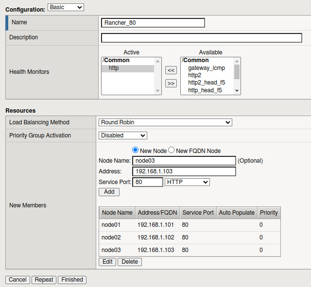
Figure 14.5 – F5 node pool configuration example
We also need to create the frontend, or what F5 calls the virtual server:
- From the F5 web interface, go to the Local Traffic | Virtual Servers | Virtual Server List page and click Create.
- Give the virtual server a name. I usually name it the same as the pool.
- For the Type option, select Performance (Layer 4).
- You'll need to enter a VIP address assigned to the load balancer for the Destination Address/Mask field.
- For the Service Port section, enter port 80 with a service type of HTTP.
- The rest of the settings can be left to the default values, and you should click the Repeat button to create another virtual server, repeating the preceding steps but for port 443 and HTTPS.

Figure 14.6 – F5 virtual server settings
At this point, we need to link the frontend (virtual server) to the backend (pool):
- Go to the virtual server and click the Resources tab.
- Set the Default Pool value to be the port 80 pool in the Load Balancing section, and click Update to apply the change.
- Repeat this process for port 443.

Figure 14.7 – F5 Binding pool and virtual server together
At this point, you should be able to access your Kubernetes/Rancher cluster via the VIP address. It is imperative to remember that this is TCP mode, so F5 is just passing traffic, meaning the ingress controller needs to handle items such as SSL.
HTTP mode
We'll follow the same steps for creating the pool as we covered in TCP mode for HTTP mode. The only changes that we need to make are in the virtual server:
- For the Virtual Server type, please select Performance (HTTP) instead of Performance (Layer 4) and click Finish.
- Repeat this process for port 443, but this time, select the server type as Standard and set SSL Profile (Client) to point to your SSL certificate.
At this point, you should be able to access your cluster just like in TCP mode, but with the difference being that the load balancer handles SSL for you, and you won't have the source IP address issues that we talked about in the previous section.
In the next section, we will cover another popular load balancer software called HAProxy.
Configuring HAProxy to work with Kubernetes
This section will cover installing and configuring HAProxy for internal and external deployments. It is essential to note the examples listed in this section are generalized to cover the most common environments. Still, you should understand that every environment and workload is different, which may require tuning and changes to the designs listed in this section. Also, in this section, we'll be using the Community Edition of HAProxy, but for users who want support and additional paid features, they do offer HAProxy Enterprise. You'll find details of the difference at https://www.haproxy.com/products/community-vs-enterprise-edition/.
First, we will cover installing HAProxy on a standalone server(s) that is not a part of the Kubernetes clusters.
Note
Before starting this process, we assume you already have the server(s) built, the latest patches applied, and your root/sudo access to the server(s). Also, as of writing, v2.5 is the current latest stable release. You should review release notes and version recommendations at the official HAProxy community site at https://www.haproxy.org/.
Installing HAProxy on Ubuntu/Debian systems
For Ubuntu and Debian-based systems, the HAProxy bundled in the default package repository lags behind the current release by a minor version or two, but more importantly, can be missing significant security until the next major release. Because we are dealing with a load balancer that might be publicly accessible and will be a valuable target for attackers, we'll want to make sure that we are running the latest versions with the most up-to-date security patches. So, we are going to use a Personal Package Archive (PPA) repository for this installation.
We need to generate our install steps by going to https://haproxy.debian.net/ and filling out the form. This will create two sets of commands, with the first set being to add the PPA repository and the second command installing HAProxy.

Figure 14.8 – PPA and Install wizard
At this point, we should have HAProxy installed on our Ubuntu server. In the next section, we'll be covering the steps for Red Hat/CentOS servers.
Red Hat/CentOS
Just like Ubuntu and Debian-based systems, the HAProxy bundled in the default package repository lags behind the current release by a minor version or two, but more importantly, can be missing significant security until the next major release. Because of this, it usually is recommended to build HAProxy from the source steps, which can be found here:
- Install the prerequisites to compile the binaries by running the following command:
yum install gcc pcre-static pcre-devel -y`
- Download the source code using the following command:
cd /opt; wget https://www.haproxy.org/download/2.5/src/haproxy-2.5.4.tar.gz"
NOTE
You should review the recommended versions before choosing a version.
- Run the following commands to build and install HAProxy:
make clean
make -j $(nproc) TARGET=linux-glibc USE_OPENSSL=1 USE_LUA=1 USE_PCRE=1 USE_SYSTEMD=1
make install
mkdir -p /etc/haproxy
mkdir -p /var/lib/haproxy
touch /var/lib/haproxy/stats
At this point, we should have HAProxy installed, and now we need to create a config file for which we'll use the example listed in the following sections as a starting point.
TCP mode
In this section, we'll be covering some example configuration files that can be used as a starting point for your environment for a TCP load balancer. It is important to note that this is the most basic configuration.
The full configuration can be found at https://github.com/PacktPublishing/Rancher-Deep-Dive/main/ch14/example-configs/haproxy/tcp-mode.cfg. But, the critical part is listed in the following example, which binds to the ports 80 and 443, and just passes traffic to the backend server nodes 01/02/03:

Figure 14.9 – HAProxy TCP mode
As we can see in the config file, we are creating a frontend and backend for both ports 80 and 443 with both configs in TCP mode, as we want the load balancer to pass traffic directly from the frontend port to the backend ports.
HTTP mode
In this section, we'll be covering some example configuration files that can be used as a starting point for your environment for an HTTP load balancer.
The full configuration can be found at https://github.com/PacktPublishing/Rancher-Deep-Dive/main/ch14/example-configs/haproxy/http-mode.cfg. The critical part in this config file is the fact that there is a single frontend for both 80 and 443 ports. Then, in the frontend, we define the SSL certificate, which is stored in /etc/haproxy/certs/star.example.com.pem. Then, following that, we have a set of access control lists (ACLs) that allows us to route traffic to different clusters in this case. Non-production traffic goes to the rke-cluster-npd cluster, with the production traffic going to rke-cluster-prd. This configuration also includes an example backend configuration that is running SSL.
This is the frontend section of the configuration:

Figure 14.10 – HAProxy HTTP mode frontend
It is important to note that because we are using HTTP mode, we can have multiple clusters and applications sharing a single load balancer. As we can see in the preceding example, we have both dev.example.com pointing to the non-production cluster and example.com pointing to the production cluster.
These are the backend settings:

Figure 14.11 – HAProxy HTTP mode backend
As you can see, we are creating two different backends with one for each cluster. We are also sending all backend traffic to port 443 (SSL) as the http-request redirect scheme https unless { ssl_fc } frontend rule handles redirecting all HTTP traffic to HTTPS.
At this point, we should have HAProxy up and running and be able to access applications that are hosted on our Kubernetes clusters. In the next section, we'll be covering MetalLB, which removes the need for a load balancer.
Installing and configuring MetalLB
Of course, the question always comes up – what if I don't want to deal with an external load balancer, but I still want my cluster to be highly available? This is where a tool called MetalLB comes into the picture. MetalLB is a load balancer for Kubernetes clusters running on bare metal using standard routing protocols. The project is still in its infancy. It should be treated as a beta version. That is explained on the Project Maturity page located at https://metallb.universe.tf/concepts/maturity/.
MetalLB can be configured in two modes. The first one we will cover is layer 2 mode, which is the most straightforward configuration, with Border Gateway Protocol (BGP) being the second mode, which is commonly being used by more advanced users/environments; for both modes, the installation steps are the same.
Run the following two commands to create the namespace and install the MetalLB controller:
kubectl apply -f https://raw.githubusercontent.com/metallb/metallb/v0.12.1/manifests/namespace.yaml
kubectl apply -f https://raw.githubusercontent.com/metallb/metallb/v0.12.1/manifests/metallb.yaml
Note
You can find more details about customizing this installation for non-Rancher clusters located at https://metallb.universe.tf/installation/, including how to use the Helm chart.
For layer 2 mode, we need to configure a range of IP addresses for MetalLB to use. It is important that this range is in the same subnet as the rest of your nodes.
Simply create the following configmap:

Figure 14.12 – MetalLB layer 2 configmap
You can find the following details of this configuration in the official documentation located at https://metallb.universe.tf/configuration/#layer-2-configuration.
For BGP mode, we need a router that supports BGP that MetalLB can connect to, an autonomous system (AS) number for MetalLB to use, and a network CIDR prefix for the cluster. The BGP configuration is also configured with a configmap; an example can be found in the following figure:

Figure 14.13 – MetalLB BGP configmap
You can find the full details for this configuration in the official documentation located at https://metallb.universe.tf/configuration/#bgp-configuration.
At this point, we should have MetalLB up and running. To use an IP address from MetalLB, we need to create a service record with the LoadBalancer type, at which point MetalLB takes care of the rest. You can find the full details at https://metallb.universe.tf/usage/.
What is ingress in Kubernetes?
A Kubernetes ingress is a standard object that defines a set of rules for routing external traffic into a Kubernetes cluster. This includes setting the SSL certificate, name, or path-based routing to different pods. The ingress rules were designed around HTTP and HTTPS traffic.
The following is an example config with the central area of the config being the rules section, which, in this example, is foo.bar.com. This rule directs the traffic to the server1 service. It is important to note that the rules section is simple and very generic. This section must follow the Kubernetes standard. This allows you to swap out ingress controllers; for example, RKE1/2 comes with nginx by default, but you can choose to replace nginx with Traefik.
But, of course, if you need to customize the ingress more than the rules section allows, you can use annotations; for example, adding nginx.ingress.kubernetes.io/ssl-redirect=true to an ingress nginx will direct all non-SSL traffic to the SSL port of that ingress. You can find all the annotations in the official documentation at https://kubernetes.github.io/ingress-nginx/user-guide/nginx-configuration/annotations/.
An example ingress config is as follows:
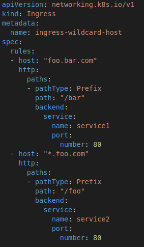
Figure 14.14 – Ingress example YAML
As you can see, we are defining an ingress for two hostnames, foo.bar.com and *.bar.com, with each hostname routing traffic to a different backend service, such as deployment. At this point, we should have an ingress set up and be able to access the test application over HTTP. But, as we know, companies and browsers require sites to support SSL as they'll throw warning messages about being insecure. So, in the next section, we'll be covering how to add an SSL certificate to this ingress.
How to add an SSL certificate to an ingress
To use an SSL certificate with your ingress, you must create a particular type of secret called kubernetes.io/tls, an example of which will be shown in a moment. It is important to note that values must encode in base64 from the PEM format. You can let kubectl handle this for you by running the following command:
kubectl create secret tls test-tls --key="tls.key" --cert="tls.crt"
It is recommended that you include the complete certificate chain in tls.crt. Also, this secret must be located in the same namespace as the ingress rule:

Figure 14.15 – TLS example YAML
Once the secret has been created, you only need to add the following section to your ingress config, which includes the secret name and the hostnames that this secret covers. You can define multiple certificates and hosts for a single ingress rule, but typically, it's recommended to keep ingresses limited to a single application:

Figure 14.16 – Adding TLS to ingress
At this point, we should be able to publish our applications that are hosted inside our cluster to the outside world using an ingress rule, while providing SSL support for our application.
Summary
This chapter went over the four main load balancer designs: round-robin DNS, passive external load balancer, active external load balancer, and an integrated load balancer. We then covered the pros and cons and some examples for each design, including making the most sense, at which point we dove into configuring a TCP and HTTP mode load balancer in an F5. We then went over the installation steps for creating an HAProxy server, including some example configs. We also covered some new software called MetalLB, which replaces a load balancer altogether. We then wrapped up the chapter by covering what an ingress is and how to make one. This is very important, as most applications that are hosted inside Kubernetes need to be published to the outside world and we need to do it in a highly available way.
In the next chapter, we'll be diving into troubleshooting Rancher and Kubernetes clusters, including how to fix some common issues and how to set up lab environments that you can use to practice recovering from these issues.