
Chapter 15
Top-Down Design with Use Case, Activity, Sequence, Component, and Class Diagrams
What's in this chapter?
- Creating and using use case and activity diagrams
- Creating and using sequence and component diagrams
- Generating code from a class diagram
Wrox.com Code Download for this Chapter
The wrox.com code downloads for this chapter are found at www.wrox.com/go/proalm3ed on the Download Code tab. The files are in the Chapter 15 download folder and individually named as shown throughout this chapter.
Chapter 14 introduced you to architecture and modeling in the software space, and hinted at all the architectural goodness available in Visual Studio Ultimate 2013. This chapter dives deeper into several aspects of that, looking at use case, activity, sequence, component, and class diagrams.
One advantage of modeling tools is that they enable you to design the architecture of the application. Part of that design process is defining common terms around the problem domain, and then ensuring that everyone on the team understands those concepts. Using the use case, activity, and sequence diagrams, you can model your application, while ensuring that everyone on the team understands exactly what is being built.
This chapter is divided into five main sections:
- Use case diagrams
- Activity diagrams
- Sequence diagrams
- Component diagrams
- Class diagrams
Each section begins with a walk-through of how to build a diagram, as well as a diagram explanation. After that, the discussion looks at all the objects available when building a particular diagram.
Use Case Diagrams
A use case diagram provides a graphical overview of the functionality of a system. It shows who is using the system and what they can do with it.
A use case diagram does not show details of use cases themselves; instead it provides a summary view of use cases, actors, and systems. Details (such as the order in which steps must be performed to accomplish the use case) can be described in other diagrams and documents, and then linked to the related use case. Use cases (and, by extension, use case diagrams) deal only with the functional requirements of a system. The architecture and any internal details are described elsewhere, using other diagrams described in this chapter, as well as Chapters 16 and 17.
Creating a Use Case Diagram
The following steps walk you through the process of creating a use case diagram. You are going to create a use case diagram of a customer interacting with an online bookstore system. The customer should be able to view the books offered and order a book. The bookstore should be able to update the list of available books, as well as deliver ordered books to the customer.
- Open Visual Studio Ultimate 2013, and create a new modeling project by selecting File ⇒ New ⇒ Project to open the New Project window. Select the Modeling Projects template, give the project a name and location, and click OK. A new modeling project opens in Solution Explorer.
- Right-click the project in Solution Explorer and select Add ⇒ New Item from the context menu.
- Select the UML Use Case Diagram template and name it
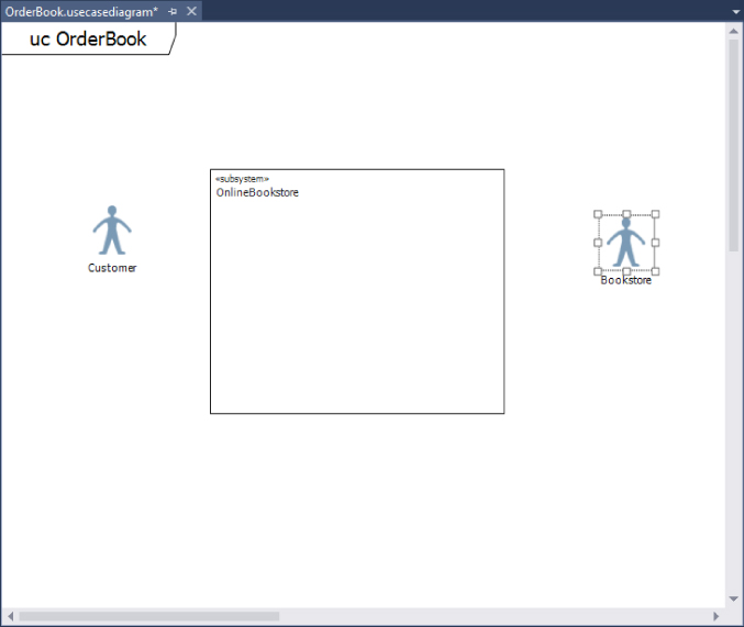
OrderBook.usecasediagram. Click the Add button to create this diagram. A blank use case diagram namedOrderBook.usecasediagramis created in the modeling project and opened as a tab in Visual Studio. - From the toolbox on the left side of Visual Studio, drag a subsystem boundary onto the use case diagram.
- In the Properties window, change the
Nameproperty for the subsystem to beOnlineBookstore. This subsystem can be used to represent either an entire system or its major components. Any use cases that the subsystem supports are drawn inside the subsystem. - Add the actors to the use case diagram. The actors represent classes of users, organizations, and external systems that interact with the system being built. By default, the
Actorobject is represented as a person icon. A different image can be used by modifying theImage Pathproperty of the object.Drop two
Actorobjects onto the use case diagram, one on either side of theOnlineBookstoresubsystem. - In the Properties window, name the left actor
Customerand the right actorBookstore. The use case diagram should appear similar to Figure 15.1. - When the actors are in place, drop the appropriate use cases onto the diagram. The use cases represent the activities that actors can perform, and appear as oval-shaped objects on the diagram.
Drop two use cases inside the
Online Bookstoresubsystem, and rename themProvide Book ListandOrder Book.Add one use case outside and below the subsystem and name itDeliver Book.TheProvide Book ListandOrder Bookuse cases are part of theOnlineBookstoreapplication, so they are drawn inside the subsystem. TheDeliver Bookuse case is outside the scope of the application, so it is drawn external to the subsystem. - Finally, to finish this simple use case, use the
Associationobject to show how each actor is related to each use case. An association indicates that an actor can take part in a particular use case. For example, theCustomeractor can view a list of books at the online bookstore.Double-click the
Associationobject in the toolbox to select it. Click and hold theCustomeractor and drag a line to theProvide Book Listuse case. An association is created between the actor and the use case. Do the same to theOrder BookandDeliver Bookuse cases. Create associations the same way between theBookstoreactor and theProvide Book ListandDeliver Bookuse cases.When finished, the use case diagram should appear similar to Figure 15.2.
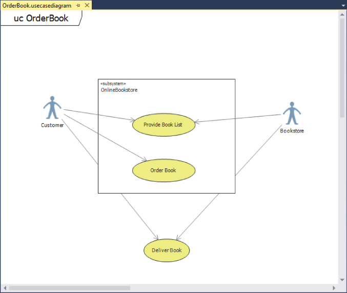
Although Figure 15.2 is a very simple use case diagram, it is still very informative. You can also have more complex use case diagrams, with multiple subsystems, actors, and use cases. A best practice is to start off describing the system with a few major use case diagrams. Each of those diagrams should define a major goal of the system. After those goals have been defined, use some of the other objects from the use case diagram toolbox to define the system in more detail.
Let's break the Order Book use case down in more detail. Figure 15.3 shows a use case diagram that does this by using the Include relationship.
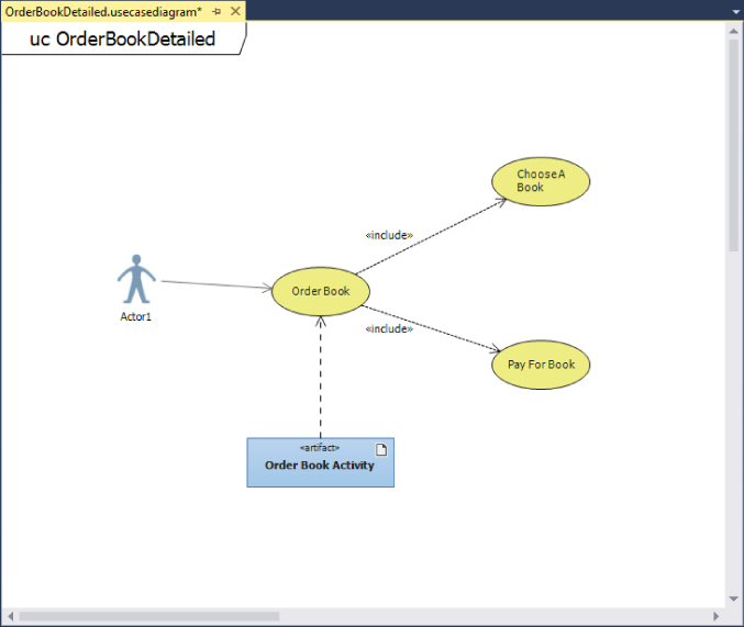
The Include relationship shows that a use case uses all the behavior of the included use case. To differentiate it from a regular association, the Include relationship is represented as a dotted line with an arrow on the end (per the UML 2.1.2 specification, available at http://aka.ms/UML212). The arrow should always point to the more detailed use case. The Include relationship is also labeled with the keyword ![]() include
include![]()
A use case diagram does not specify in what order the particular use cases should happen, or when a particular use case is necessary. To make that information clear, attach an Artifact object to the general use case by dropping an Artifact object onto the use case diagram and then dragging a Dependency relationship between the Artifact element and the general use case. An Artifact element enables you to attach a separate document to the use case (for example, a text file that describes the steps to take) or reference another diagram.
Use Case Diagram Toolbox
Figure 15.4 shows the different elements and associations available for use case diagrams.
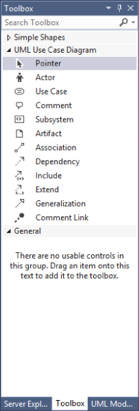
Table 15.1 describes the different elements and associations.
Table 15.1 Use Case Diagram Toolbox Objects
| Name | Description |
Pointer |
Turns the mouse back into a regular mouse pointer. |
Actor |
Adds a user or external system that interacts with a system. |
Use Case |
Adds a specification of actions that are performed in pursuit of a specific goal. |
Comment |
Adds a comment for more details. |
Subsystem |
Adds a system component. Places the use cases inside the subsystems that support it. |
Artifact |
Adds a reference to a diagram or document. |
Association |
Links an actor with a use case. |
Dependency |
Specifies that the definition of one element depends on the definition of another. |
Include |
Specifies that one use case invokes another use case. |
Extend |
Specifies that one use case extends the definition of another in specific conditions. |
Generalization |
Specifies that one element is a specialized version of another, inheriting its features and constraints. |
Comment Link |
Connects a comment to a diagram element. |
Activity Diagrams
An activity diagram is used to show a business or software process as a workflow through a series of actions. These actions could be performed by any number of objects, including people, software, or computers. Activity diagrams can be used to model the logic captured in a particular use case or to model detailed business logic. One easy way to think of activity diagrams is to think of them as a flowchart.
An activity diagram always has a starting node, a series of activities, and a final node that indicates the end of the activity.
Creating an Activity Diagram
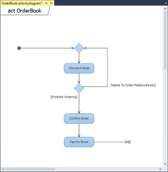
The following steps outline the process of creating an activity diagram that shows the sequence of activities for ordering a book from the online bookstore. A customer first chooses a book to order. After a book is chosen, the customer makes a decision whether to order more books or confirm the order. After the customer is finished selecting books, the customer confirms the book order and then pays for the order.
- Using the same modeling project created earlier in the “Creating a Use Case Diagram” section, right-click the project in Solution Explorer and select Add ⇒ New Item from the context menu.
- Select the UML Activity Diagram template and name it
OrderBook.activitydiagram.Click the Add button to create this diagram. A blank activity diagram namedOrderBook.activitydiagramis created in the modeling project and opened in a tab in Visual Studio. - From the toolbox, drag an
Initial Nodeelement onto the left of the diagram. This indicates the starting point for this activity. Every activity diagram requires this element. - Drag three
Actionelements onto the diagram to the right of theInitial Nodeelement. Using the properties of the elements, name these itemsChoose A Book,Confirm Order, andPay For Book. The action element represents a step in the activity that either the user or system performs. - From the toolbox, drag a
Merge Nodeabove theChoose A Bookaction. This node is used to merge multiple branches, usually split by a decision node (described shortly). AMerge Noderequires two or more inputs and has a single output. - Drag and drop a
Decision Nodebetween theChoose A BookandConfirm Orderactions. This node is used to create branching flows in the activity. For this activity diagram, after a book is chosen, the customer has a choice of confirming the order or selecting more books. ADecision Nodehas a single input and two or more outputs. - Drag an
Activity Final Nodeto the right of thePay For Bookaction. This indicates the end of the activity.
Next, you must add the connectors to show the flow of activity through this activity diagram. Double-click the Connector element to select it. On the activity diagram, drag a line between the Initial Node element and the Merge Node. Continue connecting the other elements on the diagram as follows:
- Connect the
Merge Nodeto theChoose A Bookaction. - Connect the
Choose A Bookaction with theDecision Node. - Connect the
Decision Nodewith theConfirm Orderaction. - Connect the
Decision Nodewith theMerge Node. - Connect the
Confirm Orderaction with thePay For Bookaction. - Connect the
Pay For Bookaction with theActivity Final Node. - Modify the
Guardproperty of theConnectorelements on theDecision Node, leaving theDecision Nodeto specify the reasons for the different pathways. On theConnectorto theConfirm Orderaction, add the guardFinished Ordering.On theConnectorto theMerge Node, add the guardWants To Order Multiple Books.
When it's finished, the diagram should appear similar to Figure 15.5.
Concurrent Flow in an Activity Diagram
Activity diagrams can also be used to describe a sequence of actions that execute at the same time. This sequence of actions is known as a concurrent flow. Figure 15.6 shows an example of a concurrent flow activity diagram related to ordering a book online.
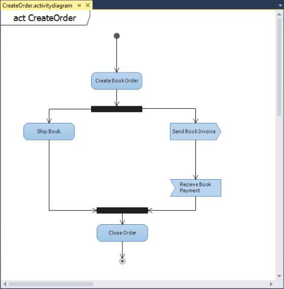
At the start of this activity diagram, an order is created. After an order is created, two different branch processes are started. The black bar that the Create Book Order action leads into is called a Fork Node, and is used to divide a single flow into concurrent flows. In this case, one flow leads to the Ship Book action. The other leads to the Send Book Invoice element.
The Send Book Invoice element is not a regular action element. It is a Send Signal Action element. This indicates an action that sends a message to another activity for something to happen. The Receive Book Payment is an Accept Event Action element. It is an action that waits for a message before the flow can continue. In the case of Figure 15.6, a book invoice will be sent, potentially to a payment system. The flow in the activity diagram waits until a response is received back, indicating that the book has been paid for. Both the Ship Book and the Receive Book Payment actions are then merged back into a single process using a Join Node. The activity ends with the closing of the order.
Activity Diagram Toolbox
Figure 15.7 shows the different elements and associations available for activity diagrams.
Table 15.2 describes the different elements and associations.
Table 15.2 Activity Diagram Toolbox Objects
| Name | Description |
Pointer |
Turns the mouse back into a regular mouse pointer. |
Initial Node |
Adds the start of the activity. |
Activity Final Node |
Adds an end to the activity. |
Action |
Adds a single step that occurs in the activity. |
Object Node |
Adds a node that can transmit, buffer, filter, and transform objects. |
Comment |
Adds a comment for more details. |
Decision Node |
Divides a single incoming flow into a choice between alternate outgoing flows. |
Merge Node |
Combines incoming alternate flows into a single outgoing flow. |
Fork Node |
Divides a single incoming flow into concurrent outgoing flows. |
Join Node |
Combines incoming concurrent flows into a single outgoing flow. |
Send Signal Action |
Adds an action that sends a signal to another system or activity. |
Accept Event Action |
Adds an action that waits for a signal or event. |
Call Behavior Action |
An action that is defined in more detail on another activity diagram. |
Call Operation Action |
An action that calls an operation on an instance of a class. |
Input Pin |
Represents data that an action requires. It allows data to flow into an action. |
Output Pin |
Represents data that an action produces. It allows data to flow out of an action. |
Activity Parameter Node |
Creates a parameter that conveys data into or out of the activity. |
Connector |
Adds a connection or flow between elements on the diagram. |
Adding an Activity Diagram to a Use Case Diagram
Earlier in this chapter when creating use case diagrams, you saw an Artifact element attached to a use case (see Figure 15.3). One available option with Artifact elements is the capability to associate them with an activity diagram (and, as an extension, any physical document).
To do this, drag an Artifact element onto the OrderBook.usecasediagram you created earlier in this chapter. In the properties window for the Artifact element, select the Hyperlink property, and click the ellipse button. This will open the Link to URL or File dialog box, allowing you to select a diagram, document, or other file to associate with the Artifact element on the use case diagram.
Sequence Diagrams
A sequence diagram is used to show the sequence of interactions among classes, components, subsystems, or actors. A sequence diagram is read from top to bottom, indicating the flow of time through the system. From left to right, the diagram itself shows the flow of control from one element to the next.
Creating a Sequence Diagram
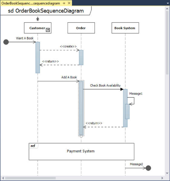
The following steps walk you through creating a sequence diagram that shows the sequence of flow for ordering a book from the online bookstore. A customer first has the desire to purchase a book. At that point, the customer adds a book to a shopping cart. The order system checks the availability of the book and performs some internal processing. The availability of the book is returned to the ordering system. The payment system is represented by a separate sequence diagram, so a reference placeholder is inserted into this diagram. Finally, a message is sent to an unknown (or unspecified) system at the end of the process.
- Using the same modeling project you have been using throughout this chapter, right-click the project in Solution Explorer, and, from the context menu, select Add ⇒ New Item.
- Select the UML Sequence Diagram template and name it
OrderBookSequenceDiagram.sequencediagram. Click the Add button to create this diagram. A blank sequence diagram namedOrderBookSequenceDiagram.sequencediagramis created in the modeling project and opened in a tab in Visual Studio. - From the toolbox, drag a
Lifelineelement onto the left of the diagram. This vertical line element represents participants in the described interaction. Time progresses down the lifeline, from top to bottom. - Using the Properties window, change the
Typeproperty to beCustomerand set theActorproperty equal toTrue. Notice theCustomerlifeline has a symbol representing a person above it. This symbol is called an actor and indicates that this lifeline represents a participant external to the system being developed. - Drag two more
Lifelineelements onto the diagram and set theTypeproperties toOrderandBook System, respectively.The gray vertical shaded rectangles on each lifeline are called execution occurrences. These represent a period when the participant is executing an operation. Execution usually begins when the participant receives a message. From within an execution block, other messages can be sent to other participants, or even back to the execution block itself.
This sequence diagram is started with a message from an unknown source. This is represented with an asynchronous message.
- Select the
Asynchronouselement in the toolbox, select a blank space to the left of theCustomerlifeline, and draw a line to theCustomerlifeline. This creates the starting point into the sequence diagram, indicated by a black dot. This initial message is known as a found message. Change theNameproperty toWant A Book. - A create message must be sent to create a participant. If a participant receives a create message, it should be the first message he receives. Click the
Createelement in the toolbox. On theCustomerlifeline, click the gray execution box area and drag a line to theOrderlifeline. A dotted line is created between the two lifelines, and a gray execution box appears on theOrderlifeline.To start the ordering process, the customer must add an item that she wants to buy. This is represented using an
Asynchronousmessage call. AnAsynchronouselement represents an interaction where the sender can continue immediately without waiting for the receiver. - In the toolbox, select the
Asynchronouselement. Click theCustomerlifeline and drag a line to theOrderlifeline. A solid line is created between theCustomerandOrderlifelines. Change the name of the element toAdd A Book. - After a book is added, the book availability must be determined. This is done using a
Synchronousmessage call. ASynchronouselement represents an interaction where the sender waits for the receiver to return a response.In the toolbox, select the
Synchronouselement. Click on the execution block on theOrderlifeline and drag a line to theBook Systemlifeline. A solid arrow is created between theOrderandBooklifelines. In addition, a dotted arrow is created from theBook Systemlifeline to theOrderlifeline. This indicates control is to be returned to the sender—in this case, theOrderlifeline. - Change the name of the element to
Check Book Availability. - A participant can also send a message to itself—for example, if it were triggering internal methods for doing work. These messages are called self messages.
Select the
Asynchronouselement from the toolbox. On theBook Systemlifeline, click theCheck Book Availabilityexecution block. Drag a line farther down in the same block and release. This creates a solid arrow from theCheck Book Availabilityexecution block back onto the same execution block. - There is a complete payment system sequence that is not represented on this particular sequence diagram, but instead is shown on a separate diagram. To represent the contents of that separate diagram, use the
Interaction Useelement.Click the
Interaction Useelement in the toolbox. Drag a box across all three lifelines, as all three are included in this reference. Change the name of the element toPayment System. - You can represent a message to an unknown or unspecified participant. This is known as a lost message.
Select the
Asynchronouselement from the toolbox. At the bottom of theBook Systemlifeline, drag a line from the lifeline to a blank area on the diagram. An arrow is created from the lifeline to a created black dot, indicating this message goes to an unknown participant.When finished, the diagram should appear similar to Figure 15.8.
Sequence Diagram Toolbox
Figure 15.9 shows a screenshot of the different elements available for sequence diagrams.
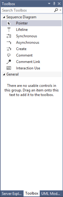
Table 15.3 describes the different elements and associations.
Table 15.3 Sequence Diagram Toolbox Objects
| Name | Description |
Pointer |
Turns the mouse back into a regular mouse pointer. |
Lifeline |
Adds a participant (such as a class or object) to an interaction sequence. |
Synchronous |
Adds a message that calls an operation and expects a response. |
Asynchronous |
Adds a message that calls an operation but does not expect a response. |
Create |
Adds a message that calls an operation that creates an instance of the target. |
Comment |
Adds a comment for more details. |
Comment Link |
Connects a comment to a diagram element. |
Interaction Use |
Adds an interaction use to create a reusable sequence or to reference another sequence. |
Component Diagrams
A sequence diagram enables you to model and visualize the messages of a system. With the component diagram, you can visualize the components of the system that implement the system functionality, as well as other puzzle pieces of the system (such as web services, user interfaces, COM components, and so on). A component diagram depicts the relationships between various components of your application or system.
A component diagram shows the parts of a design for a software system. These components could be executables, DLLs, or even entire systems. At this level, you aren't necessarily trying to decide exactly how things are being built. Rather, you are just trying to break down the architecture into something more manageable and understandable. You can use a component diagram to visualize the high-level structure of the system and the service behavior that the components both provide and consume.
Think of a component as a modular unit that is replaceable. You don't know how the internals of the component work. Instead, you know what interfaces a component provides or consumes. Components on a component diagram have interfaces, either required interfaces or provided interfaces. An interface can be anything, from a website to a web service. A required interface indicates functionality that a component expects to consume. A provided interface indicates functionality that a component provides for other components to consume. Each required interface on a component diagram should be linked to a provided interface.
Creating component diagrams has a couple of nice benefits. It can help the development team understand an existing design and see potential ways to improve it. More importantly, thinking of the system as a collection of components with well-defined interfaces improves the separation between components, which can make the design easier to change as the requirements change.
Creating a Component Diagram
Use the following steps to create a component diagram that represents the different components of the online bookstore system. The different components include a web browser, the bookstore's website (both the web application and the back-end database), the bookstore's payment system, and a way to process credit cards.
- Using the same modeling project as used in previous sections, right-click the project in Solution Explorer and select Add ⇒ New Item from the context menu.
- Select the UML Component Diagram template and name it
BookComponents.componentdiagram. Click the Add button to create this diagram. A blank component diagram namedBookComponents.componentdiagramis created in the modeling project and opened in a tab in Visual Studio. - There are two options for adding components to the diagram:
- Using the toolbox, click the
Componentelement, then click a blank area of the diagram. An emptyComponentelement appears on the diagram. This is useful for creating new components. - You can also add existing components from other diagrams in the same modeling project to the diagram. Either open the existing diagram or open the UML Model Explorer window (by selecting View ⇒ Other Windows ⇒ UML Model Explorer). Right-click the component to add to the component diagram and then select Copy. Right-click a blank area of the component diagram and select Paste Reference to create a copy of the component on the new diagram.
- Using the toolbox, click the
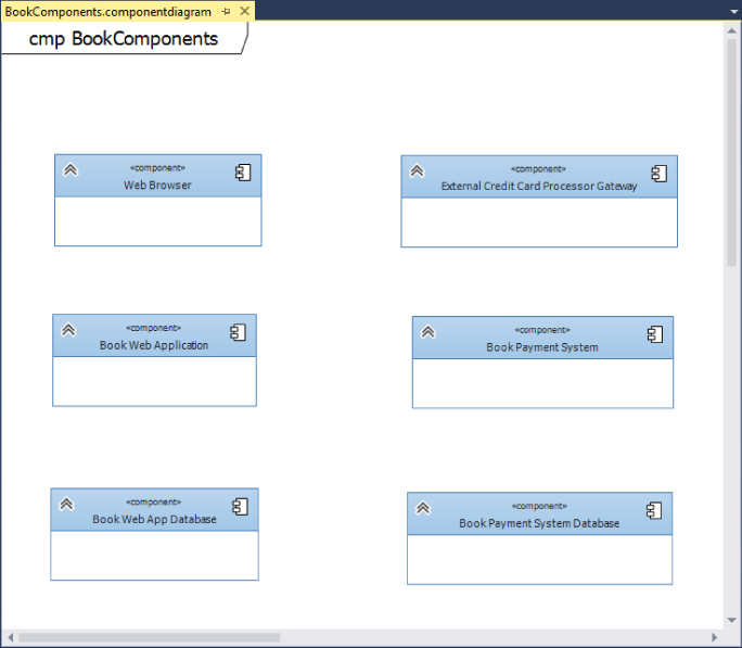
- From the Toolbox window, click the
Componentelement and click a blank area on the diagram to create a newComponentelement. Select the component and change its name toWeb Browser. Using this same method, add the following components to the component diagram:Book Web ApplicationBook Web App DatabaseExternal Credit Card Processor GatewayBook Payment SystemBook Payment System Database
After you've added these components, the component diagram should resemble Figure 15.10.
- From the Toolbox window, click the
Provided Interfaceelement and then click theBook Web Applicationcomponent. The provided interface symbol (or lollipop) attaches itself to theBook Web Applicationcomponent with a default name ofInterface1. This component is going to represent the website used for ordering books. Select theProvided Interfaceelement, and, in the Properties window, rename itBook Web Site. - Add another
Provided Interfaceelement to theBook Payment Systemcomponent, and name itIBookPaymentService. This element exposes a web service for interacting with the payment system. Finally, add aProvided Interfaceelement to theExternal Credit Card Processor Gatewaycomponent and name itICreditCardProcessingGateway. This element exposes a web service for interacting with the external credit card processor. - Add the required interfaces. A required interface represents behavior that a component consumes through an interface. As with adding components to the diagram, there are two options for adding interfaces (both required and provided interfaces) to the diagram. You can add a new interface from the Toolbox window, or, using the UML Model Explorer, you can drag an existing interface onto the diagram.
- You must show that the
Web Browsercomponent utilizes the book website interface exposed by theBook Web Applicationcomponent.From the toolbox, click the
Required Interfaceelement and then click theWeb Browsercomponent on the diagram. Rename the interface toBook Web Site. - Add a required interface to the
Book Web Applicationby using the UML Model Explorer. If the UML Model Explorer window is not visible, open it by going to View ⇒ Other Windows ⇒ UML Model Explorer in Visual Studio. - The UML Model Explorer shows all the elements that have been added to the central model. In the UML Model Explorer, click and drag the
IBookPaymentServiceinterface to theBook Web Applicationcomponent. This creates another instance of theIBookPaymentServiceprovided interface. - You need this interface to be a required interface. To change the interface type, select the
IBookPaymentServiceprovided interface on theBook Web Applicationcomponent. Click the smart tag that appears near the element and select Convert to Required Interface. The interface type changes fromProvidedtoRequired. - Select the
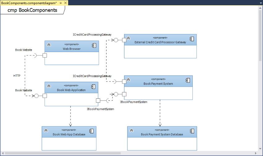
Required Interfaceelement in the Toolbox window and click theBook Payment Systemcomponent to create a required interface on that component. Rename the interface to beICreditCardProcessingGateway. The component diagram should now resemble Figure 15.11. - Next you need to show which provided interfaces satisfy which required interfaces by using the
Dependencyelement. ADependencyelement always connects a required interface (or hook) to a provided interface (or lollipop).In the Toolbox window, select the
Dependencyelement. On the component diagram, select theBook Web Siterequired interface on theWeb Browsercomponent and then select theBook Web Siteprovided interface on theBook Web Applicationcomponent. A dotted arrow is created from the required interface to the provided interface, indicating that the provided interface satisfies the required interface. On the component diagram, select the dependency dotted arrow that was just created. In the Properties window, change the name to beHTTP. This provides a visual indicator on the component diagram that this is an HTTP connection between the two components. - In the Toolbox window, select the
Dependencyelement again. On the component diagram, select theIBookPaymentServicerequired interface on theBook Web Applicationcomponent. Then select theIBookPaymentServiceprovided interface on theBook Payment Systemcomponent. Finally, select theDependencyelement from the toolbox and connect theICreditCardProcessingGatewayrequired interface on theBook Payment Systemcomponent to theICreditCardProcessingGatewayprovided interface on theExternal Credit Card Processor Gateway. - Create the dependency relationship between the
Book Web Applicationand theBook Web App Databasecomponents by selecting theDependencyelement from the Toolbox window, clicking theBook Web Applicationcomponent, and then clicking theBook Web App Databasecomponent. A dotted arrow is drawn between the two, indicating the dependency of the web application on the database. Do the same thing between theBook Payment Systemcomponent and theBook Payment System Databasecomponent. The component diagram is now complete, as shown in Figure 15.12.

Component Diagram Toolbox
Figure 15.13 shows the different elements and associations available for component diagrams.
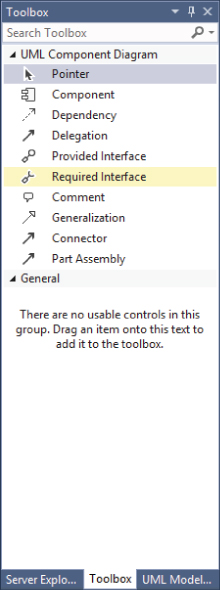
Table 15.4 describes the different elements and associations.
Table 15.4 Component Diagram Toolbox Objects
| Name | Description |
Pointer |
Turns the mouse back into a regular mouse pointer. |
Component |
Adds a component that defines a reusable unit of system functionality. |
Dependency |
Defines how an element depends on another element. Begins the relationship from the dependent element. |
Delegation |
Designates behavior between a port on an outer component and an interface on an inner component. |
Provided Interface |
Adds an interface that a component provides to other components. |
Required Interface |
Adds an interface that a component requires from other components. |
Comment |
Adds a comment for more details. |
Generalization |
Defines how a component derives from another component. Begins the relationship from the derived component. |
Connector |
Creates a default relationship between shapes based on the types of shapes being connected. |
Part Assembly |
Specifies a connection between parts in a component. Connects a required interface on one part to a provided interface on another part. |
Class Diagrams
Class diagrams depict the classes within an application or system and the relationship that exists between them. Different symbols represent the varying relationships that may exist (such as inheritance or association). This information is described independent of any reference to a particular implementation of the class. The purpose of the class diagram is to focus on the logical aspects of the classes instead of how they are implemented.
In a class diagram, a type is a class, interface, or enumeration. Class and interface objects can have attributes defined. An attribute is a value that can be attached to an instance of a class or an interface. Classes and interfaces can also have operations defined. An operation is a method or function that can be performed by an instance of a class or interface.
On a class diagram, you can draw associations between any pairs of types. An association indicates that the system being developed stores links between the instances of the associated types. An association is a diagrammatic method of showing an attribute or pair of attributes. For example, if you have a class BookStore that has an attribute of type Book, you can state that definition by drawing an association between Bookstore and Book.
Using the UML Model Explorer, you can locate interfaces you have defined on the component diagram and drag those directly onto the class diagram to create them.
Creating a Class Diagram
Use the following steps to create a class diagram that shows the relationship between a Store class, a BookStore class, and a Books class. A bookstore is a more specific version of a store, and a bookstore contains multiple books.
- Using the same modeling project from before, right-click the project in Solution Explorer, and, from the context menu, select Add ⇒ New Item.
- Select the UML Class Diagram template and name it
BooksClassDiagram.classdiagram. Click the Add button to create this diagram. A blank UML class diagram namedBooksClassDiagramis created in the modeling project and opened in a Visual Studio Tab. - In the Toolbox tab, click the
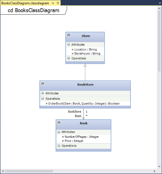
Classelement and then click a blank space on the UML class diagram. This creates a class object on the diagram. In the properties for the class, change the name to beStore. This is going to be a generic store class that the bookstore object inherits from. Set theIs Abstractproperty of theStoreclass toTrue, to indicate it is an abstract class. - The
Storeclass has a couple of generic attributes that apply to all stores, such as location and store hours.Right-click the
Storeclass and select Add ⇒ Attribute to create a new attribute. Name the attributeLocation. Select theLocationattribute, and, in the Properties window, set theTypeproperty to beString. Add a second attribute namedStoreHoursand set its type to beStringas well. - Create the bookstore class. The bookstore class inherits from the
Storeclass created earlier, as it is a specialized type of store.Using the Toolbox window, add another
Classobject to the diagram, under theStoreobject, and name itBookStore. Select theInheritanceelement in the Toolbox window. Click theBookStoreclass and then click theStoreclass. A solid arrow appears that points from theBookStoreclass to theStoreclass, indicating that theBookStoreinherits from theStore.The inherited operations and attributes are not typically shown on specialized types, which is why the
Storeclass attributes are not displayed on theBookStoreclass. However, you can use the smart tag on the inheritance arrow to add inherited operations to the specialized class. Simply click the smart tag and select Override Operations. Then select which operations to show on the specialized class. - Now create a class for the books. Add another class object to the class diagram, below the
BookStoreclass, and rename itBook. Add two attributes to theBookclass:Priceof typeIntegerandNumberOfPagesof typeInteger. Select theAssociationelement from the Toolbox window, click theBookStoreclass, and then click on theBookclass. AnAssociationelement is used to represent any kind of linkage between two elements, regardless of how the linkage is actually implemented in the code itself. - A
BookStorecan have multiple books in it, so you must modify theMultiplicityproperty for theBookclass.Select the
Associationlinking theBookStoreandBookclasses. In the Properties window, click the arrow next to theSecond Roleproperty to expand it. Change theMultiplicityvalue to be*, indicating theBookStorecan contain multiple books. - Add an operation for ordering books to the
BookStoreclass. Right-click the class and select Add ⇒ Operation. Name the operationOrderBook. - You must set the parameters and the return type for this operation by selecting the
OrderBookoperation and going to the Properties window. In the Properties window, set theReturn Typeto beBoolean. Click the ellipsis in theParametersfield to open the Operation Parameter Collection Editor window.In the Parameter Collection Editor window, click the Add button to create a new parameter. Set the name of the parameter to be
Item, and the type to beBook. Click the Add button again to create a second parameter namedQuantitywith a type ofInteger. Click the OK button to close the Operation Parameter Collection Editor window.
Figure 15.14 shows the final result of the class diagram.
Class Diagram Toolbox
Figure 15.15 shows the different elements and associations available for class diagrams.
Table 15.5 describes the different elements and associations.
Table 15.5 Class Diagram Toolbox Objects
| Name | Description |
Pointer |
Turns the mouse back into a regular mouse pointer. |
Class |
Adds a type that defines a class. |
Interface |
Adds an interface to specify the attributes and operations that classes require to realize this interface. |
Enumeration |
Adds a type that defines a list of specific values. |
Package |
Adds a package to organize types according to their namespaces. |
Comment |
Adds a comment for more details. |
Association |
Defines how an element interacts with another element. Begins the relationship from the referencing type. |
Aggregation |
Specifies that the source type refers to parts of the target type. The parts can be shared with another owner. |
Composition |
Specifies that the source type has parts of the target type. The parts cannot be shared with another owner. |
Dependency |
Defines how a type depends on another type. Begins the relationship from the dependent type. |
Inheritance |
Defines how a type inherits or realizes the members of another type. |
Package Import |
Defines how a package imports types defined in another package. Begins the relationship from the package that uses another package. |
Connector |
This connection tool creates a default relationship between shapes, based on the types of shapes being connected. |
Generating Code from a UML Class Diagram
Visual Studio Ultimate 2013 allows you to generate code from a UML class diagram. Using the class diagram as a base, you can generate skeleton code from the class diagram elements. You can also create UML class diagrams from your code base.
To generate code from a class diagram, right-click the class diagram and select Generate Code from the context menu. By default, executing this command generates a C# type for each type on the UML class diagram. The following are the default results for generating code:
- A C# type is produced for each type on the UML model. Each type is placed in a separate code file.
- A C# property is generated for each attribute of a UML class.
- A C# method is generated for each operation of a UML class.
- A C# field is generated for each navigable association in which the class participates.
- If the UML type is contained in a package, the generated C# type is placed inside a namespace, and the file is generated in a folder with the same name as the namespace.
However, you can customize this behavior—including the language generated as well as the different outputs—by modifying the text templates that are used for generating the code.
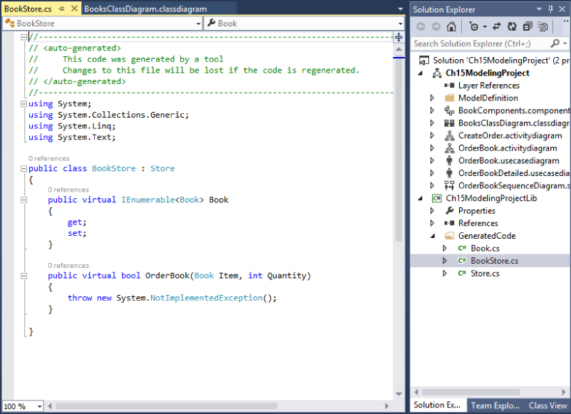
Figure 15.16 shows the BookStore.cs C# class that was generated by running the Generate Code command against the BooksClassDiagram.classdiagram class diagram created earlier in this Section. A new class named BookStore that inherits from the Store class was created. Also, a stub method for the operation OrderBook was created.
Summary
This chapter examined the capabilities of use case, activity, sequence, component, and class diagrams. You looked at how to create a use case diagram, and learned about its different components. Next, you learned about activity diagrams, where, in addition to examining an example of how to build a diagram, you also learned how to link an activity diagram back to a use case diagram. You then examined sequence diagrams, their components, and how to create them.
You learned the purpose behind component diagrams, how to create them, and the different elements available to component diagrams. Finally, you learned about class diagrams and how they are used. You learned about the different elements that are available for class diagrams and concluded the chapter with a look at how to generate code from a class diagram.
Chapter 16 discusses how you can use the Architecture Explorer to drill down into the existing project, which helps you to understand the different aspects of the project. The information in the Architecture Explorer can then be turned into a graphical view by creating a dependency graph. Finally, you will learn about code maps, a new feature in Visual Studio Ultimate 2013 to help you better understand your code base.