10
Software Reliability
10.1 Introduction
Software is now part of the operating system of a very wide range of products and systems, and this trend continues to accelerate with the opportunities presented by low cost microcontroller devices. Software is relatively inexpensive to develop, costs very little to copy, weighs nothing, and does not fail in the ways that hardware does. Software also enables greater functionality to be provided than would otherwise be feasible or economic. Performing functions with software leads to less complex, cheaper, lighter and more robust systems. Therefore software is used increasingly to perform functions that otherwise would be performed by hardware, and even by humans. Recent examples are aircraft flight control systems, robotic welders, engine control systems, domestic bread-making machines, and so on.
The software ‘technology’ used today is the same basic sequential digital logic first applied in the earliest computers. The only significant changes have been in the speed and word length capability of processors and the amount of memory available, which in turn have enabled the development of high-level computer languages and modern operating systems. Some attempts have been made to develop radically different approaches such as parallel processing and fuzzy logic, but these remain fringe applications. Therefore, the basic principles of software development, to ensure that programs are correct, safe and reliable, remain largely unchanged since they were first described in the 1970s (e.g. Myers, 1976).
Every copy of a computer program is identical to the original, so failures due to variability cannot occur. Also, software does not degrade, except in a few special senses,1 and when it does it is easy to restore it to its original standard. Therefore, a correct program will run indefinitely without failure, and so will all copies of it. However, software can fail to perform the function intended, due to undetected errors. When a software error (‘bug’) does exist, it exists in all copies of the program, and if it is such as to cause failure in certain circumstances, the program will always fail when those circumstances occur.
Software failures can also occur as a function of the machine environment, for example, machines can be restarted and the software ‘fixed’ by clearing queues, removing memory leaks, and refreshing the state of the machine. So identical copies can behave differently depending on their ‘age’ since rebooting.
Software errors can cause system failure effects that can range from trivial to catastrophic. Therefore, software reliability and safety effort must be directed at the consequences of errors, not just at the prevention or removal of most of them.
Since most programs consist of very many individual statements and logical paths, all created by the efforts of humans, there is ample scope for errors. Therefore we must try to prevent the creation of errors, and maximize the likelihood of detecting and correcting those that are created, by imposing programming disciplines, by checking and by testing.
When software is an integral part of a hardware-software system, system failures might be caused by hardware failures or by software errors. When humans are also part of the system they can also cause failures (e.g. the Airbus crash during a low flying display, which some ‘experts’ immediately blamed on the new flight control software, but which the investigation concluded was caused by the pilot putting the aircraft into a situation from which the system could not prevent the crash). In some cases, it might be difficult to distinguish between hardware, software and human causes.
There are several ways by which hardware and software reliability differ. Some have already been mentioned. Table 10.1 lists the differences.
10.2 Software in Engineering Systems
The software that forms an integral part or sub-system of an engineering system is in some important ways different from software in other applications, such as banking, airline booking, logistics, CAE, PC operating systems and applications, and so on. The differences are:
- Engineering programs are ‘real time’: they must operate in the system timescale, as determined by the system clock and as constrained by signal propagation and other delays (switches, actuators, etc.). A chess program or a circuit simulation program, for example, will run when executed, and it is not critical exactly how long it takes to complete the run. However, in an operational system such as a process controller or an autopilot, it is essential that the software is ready to accept inputs and completes tasks at the right times. The software must be designed so that functions are correctly timed in relation to the system clock pulses, task execution times, interrupts, and so on. Timing errors are a common cause of failure in real-time systems, particularly during development. They are often difficult to detect, particularly by inspection of code. Timing errors can be caused by hardware faults or by interface problems. However, logic test instruments (logic analysers) can be used to show exactly when and under what conditions system timing errors occur, so that the causes can be pinpointed.
- Engineering programs share a wider range of interfaces with the system hardware. In addition to basic items such as processors, memory, displays and keyboards, other engineering interfaces can include measurement sensors, A/D and D/A converters, signal analysers, switches, connectors, and so on.
- Engineering programs might be ‘embedded’ at different levels within a system: for example the main operating program might be loaded and run from disc or accessible PROM devices, but other software might be embedded in components which are less accessible, such as ASICs, programmable gate arrays, signal processing ICs and flash memory devices. The BIOS chip in a PC is also an example of software embedded in this way.
- There is often scope for alternative solutions to design problems, involving decisions on which tasks should be performed by hardware (or humans) and which by software.
- Engineering software must sometimes work in electrically ‘noisy’ environments, so that data might be corrupted.
- Engineering programs are generally, though not always, rather smaller and simpler than most other applications.
Table 10.1 Comparison of Hardware and Software Reliability Characteristics.
| Hardware | Software |
| 1 Failures can be caused by deficiencies in design, production, use and maintenance. | Failures are primarily due to design faults. Repairs are made by modifying the design to make it robust against the condition that triggered the failure. |
| 2 Failures can be due to wear or other energy-related phenomena. Sometimes warning is available before failure occurs (e.g. system can become noisy indicating degradation and impending failure). | There are no wearout phenomena. Software failures occur without warning, although very old code can exhibit an increasing failure rate as a function of errors introduced into the code while making functional code upgrades. |
| 3 No two items are identical. Failures can be caused by variation. | There is no variation: all copies of a program are identical. |
| 4 Repairs can be made to make equipment more reliable. This would be the case with preventive maintenance where a component is restored to an as new condition. | There is no repair. The only solution is redesign (reprogramming), which, if it removes the error and introduces no others, will result in higher reliability. |
| 5 Reliability can depend on burn-in or wearout phenomena; that is, failure rates can be decreasing, constant or increasing with respect to time. | Reliability is not so time-dependent. Reliability improvement over time may be affected, but this is not an operational time relationship. Rather, it is a function of reliability growth of the code through detecting and correcting errors. |
| 6 Reliability may be time-related, with failures occurring as a function of operating (or storage) time, cycles, etc. | Reliability is not time related. Failures occur when a specific program step or path is executed or a specific input condition is encountered, which triggers a failure. |
| 7 Reliability may be related to environmental factors (temperature, vibration, humidity, etc.) | The external environment does not affect reliability except insofar as it might affect program inputs. However, the program reliability is a function of the internal machine environment (queues, memory leakage, etc.) |
| 8 Reliability can be predicted, in principle but mostly with large uncertainty, from knowledge of design, parts, usage, and environmental stress factors. | Reliability cannot be predicted from any physical bases, since it entirely depends on human factors in design. Some approaches exist based on the development process used and the extent of the code, but these are controversial. |
| 9 Reliability can be improved by redundancy. The successful use of redundancy presumes ready detection, isolation, and switching of assets. | Reliability cannot be improved by redundancy if the parallel paths are identical, since if one path fails, the other will have the error. It is possible to provide redundancy by having diverse parallel paths with different programs written by different teams. |
| 10 Failures can occur in components of a system in a pattern that is, to some extent, predictable from the stresses on the components and other factors. Reliability critical lists are useful to identify high risk items. | Failures are rarely predictable from analyses of separate statements. Errors are likely to exist randomly throughout the program, and any statement may be in error. Most errors lie on the boundary of the program or in its exception handling. Reliability critical lists are not appropriate. |
| 11 Hardware interfaces are visual; one can see a Ten-pin connector. | Software interfaces are conceptual rather than visual. |
| 12 Computer-aided design systems exist that can be used to create and analyse designs. | There are no computerized methods for software design and analysis. Software design is more of an ‘art form’ lacking the provability of hardware, except to a limited extent through formal methods (see later). |
| 13 Hardware products use standard components as basic building blocks. | There are no standard parts in software, although there are standardised logic structures. Software reuse is being deployed, but on a limited basis. |
Therefore, it is very important that engineering software is developed (specified, designed, programmed, tested, managed) in close integration with the hardware and overall system work. The not uncommon practice of writing a software specification then ‘outsourcing’ the program development work should not be an option for important engineering software.
10.3 Software Errors
Software errors (‘bugs’) can arise from the specification, the software system design and from the coding process.
10.3.1 Specification Errors
Typically more than half the errors recorded during software development originate in the specification. Since software is not perceivable in a physical sense, there is little scope for common sense interpretation of ambiguities, inconsistencies or incomplete statements. Therefore, software specification must be very carefully developed and reviewed. The software specification must describe fully and accurately the requirements of the program. The program must reflect the requirements exactly. There are no safety margins in software design as in hardware design. For example, if the requirement is to measure 9 V ± 0.5 V and to indicate if the voltage is outside these tolerances, the program will do precisely that. If the specification was incorrectly formulated, for example, if the tolerances were not stated, the out-of-tolerance voltage would be indicated at this point every time the measured voltage varied by a detectable amount from 9 V, whether or not the tolerances were exceeded. Depending upon the circumstances this might be an easily detectable error, or it might lead to unnecessary checks and adjustments because the out-of-tolerance indication is believed. This is a relatively simple example. Much more serious errors, such as a misunderstanding or omission of the logical requirement of the program, can be written into the specification. This type of error can be much harder to correct, involving considerable reprogramming, and can be much more serious in effect.
The Eurospace Ariane 5 spacecraft launcher failure was caused by such an error: the guidance computer and the inertial measurement unit used different bit formats for numerical data, but, even though this fact was known, no compensation was made because it had not resulted in failures on previous Ariane launchers. The new launcher's greater rocket thrust led to an overflow when the inertial unit measured velocities higher than experienced before. The NASA Mars Polar Orbiter spacecraft collided with the planet because part of the system was designed using measurements in miles while an interfacing subsystem used kilometres.
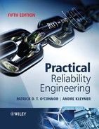
The specification must be logically complete. Consider the statement: ‘Sample inputs A, B and C. If any one exceeds by > ± 10 units the average of the other two, feed forward the average of these two. Indicate failure of the out-of-tolerance input. If the out-of-tolerance condition does not exist, feed forward the average of the three inputs.’
This is an example of a two-out-of-three majority voting redundant system. The logic is shown in the flow diagram, Figure 10.1. Consider the situation when the values of A, B and C are 100, 90 and 120. The values of the derived parameters, and route taken by the program, are shown in Figure 10.1. In this case, two fault conditions exist, since both B and C exceed the average of the other two inputs. The program will indicate a B failure, as the algorithm compares B before C. The specification has not stated what should happen in the event of more than one input being out of tolerance. The program will work as shown in the algorithm, in the sense that an input will always be available, but the system may not be safe. The flowchart complies with the specification, but it probably does not reflect the real wishes of the specification writer. A software specification must cover all the possible input conditions and output requirements, and this usually requires much more detailed consideration than for a hardware specification.
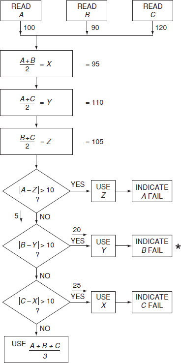
Figure 10.1 Voting redundant system.
The specification must be consistent. It must not give conflicting information or use different conventions in different sections (e.g. miles and kilometres).
The specification must not include requirements that are not testable, for example, accuracy or speed requirements that are beyond the capability of the hardware.
The specification should be more than just a description of program requirements. It should describe the structure to be used, the program test requirements and documentation needed during development and test, as well as basic requirements such as the programming language, and inputs and outputs. (Program structure, test and documentation will be covered later.)
10.3.2 Software System Design
The software system design follows from the specification. The system design may be a flowchart and would define the program structure, test points, limits, and so on. Errors can occur as a result of incorrect interpretation of the specification, or incomplete or incorrect logic. Errors can also occur if the software cannot handle data inputs that are incorrect but possible, such as missing or incorrect bits.
An important reliability feature of software system design is robustness, the term used to describe the capability of a program to withstand error conditions without serious effect, such as becoming locked in a loop or ‘crashing’. The robustness of the program will depend upon the design, since it is at this stage that the paths to be taken by the program under error conditions are determined.
10.3.3 Software Code Generation
Code generation is a prime source of errors, since a typical program involves a large number of code statements. Typical errors can be:
- Typographical errors. (sic).
- Incorrect numerical values, for example, 0.1 for 0.01.
- Omission of symbols, for example, parentheses.
- Inclusion of variables which are not declared, or not initialized at the start of program run.
- Inclusion of expressions which can become indeterminate, such as division by a value which can become zero.
- Accidental shared use of memory locations.
Changes to code can have dire consequences. The likelihood of injecting new faults can run as high as 50%, and tends to be highest for small code changes. The injected faults tend to be more obscure and harder to detect and remove. Changes can be in conflict with the original architecture and increase code complexity.
We will briefly describe the methods that can be used to minimize the creation of errors, and to detect errors that might have been created.
10.4 Preventing Errors
10.4.1 Specification
The overall system specification and the software specification must be prepared in harmony. Both should allow flexibility in relation to allocation of functions and should encourage integrated engineering.
Software specifications should be more than just descriptions of requirements. They must describe the functions to be performed, in full and unambiguous detail, and the operating environment (hardware, memory allocation, timing, etc.). They should also describe explicitly all of the conditions that must NOT be allowed to occur. They should describe the program structure to be used, the program test requirements and documentation needed during development, as well as basic requirements such as the programming language, memory allocations, inputs and outputs. By adequately specifying these aspects, a framework for program generation will be created which minimizes the possibilities for creating errors, and which ensures that errors will be found and corrected.
The specifications must be carefully reviewed, to ensure that they meet all of the requirements described above, and contain no ambiguities. Specification review must be performed by the project team, including the programmers and engineers whose work will be driven by the specifications.
10.5 Software Structure and Modularity
10.5.1 Structure
Structured programming is an approach that constrains the programmer to using certain clear, well-defined approaches to program design, rather than allowing total freedom to design ‘clever’ programs which might be complex, difficult to understand or inspect, and prone to error. A major source of error in programs is the use of the GOTO statement for constructs such as loops and branches (decisions). The structured programming approach therefore discourages the use of GOTOs, requiring the use of control structures which have a single entry and a single exit. For example, the simple branch instruction in Figure 10.2 can be programmed (using BASIC) in either an unstructured or a structured way as shown. The unstructured approach can lead to errors if the wrong line number is given (e.g. if line numbers are changed as a result of program changes), and it is difficult to trace the subroutines (A, B) back to the decision point.
On the other hand, the structured approach eliminates the possibility of line number errors, and is much easier to understand and to inspect.
Structured programming leads to fewer errors, and to clearer, more easily maintained software. On the other hand, structured programs might be less efficient in terms of speed or memory requirements.
10.5.2 Modularity
Modular programming breaks the program requirement down into separate, smaller program requirements, or modules, each of which can be separately specified, written and tested. The overall problem is thus made easier to understand and this is a very important factor in reducing the scope for error and for easing the task of checking. The separate modules can be written and tested in a shorter time, thus reducing the chances of changes of programmer in mid-stream.
Each module specification must state how the module is to interface with other parts of the program. Thus, all the inputs and outputs must be specified. Structured programming might involve more preparatory work in determining the program structure, and in writing module specifications and test requirements. However, like good groundwork in any development programme, this effort is likely to be more than repaid later by the reduced overall time spent on program writing and debugging, and it will also result in a program which is easier to understand and to change. The capability of a program to be modified fairly easily can be compared to the maintainability of hardware, and it is often a very important feature. Program changes are necessary when logical corrections have to be made, or when the requirements change, and there are not many software development projects in which these conditions do not arise.

Figure 10.2 Structured versus unstructured programming.
The optimum size of a module depends upon the function of the module and is not solely determined by the number of program elements. The size will usually be determined to some extent by where convenient interfaces can be introduced. As a rule of thumb, modules should not normally exceed 100 separate statements or lines of code in a high level language, and less in assembler code.
10.5.3 Requirements for Structured and Modular Programming
Major software customers specify the need for programs to be structured and modular, to ensure reliability and maintainability. These disciplined approaches can greatly reduce software development and life cycle costs. ISO/IEC90003 covers structured and modular programming in more detail.
10.5.4 Software Re-Use
Sometimes existing software, for example from a different or previous application, can be used, rather than having to write a new program or module. This approach can lead to savings in development costs and time, as well as reducing the possibility of creating new errors. However, be careful! Remember Ariane 5 and Mars Polar Orbiter!
Computer-aided design systems, for example Labview¯ and Simulink¯, include embedded software for components in their databases.
10.6 Programming Style
Programming style is an expression used to cover the general approach to program design and coding. Structured and modular programming are aspects of style. Other aspects are, for example, the use of ‘remark’ statements in the listing to explain the program, ‘defensive’ programming in which routines are included to check for errors, and the use of simple constructs whenever practicable. Obviously, a disciplined programming style can have a great influence on software reliability and maintainability, and it is therefore important that style is covered in software design guides and design reviews, and in programmer training.
10.7 Fault Tolerance
Programs can be written so that errors do not cause serious problems or complete failure of the program. We have mentioned ‘robustness’ in connection with program design, and this is an aspect of fault tolerance. A program should be able to find its way gracefully out of an error condition and indicate the error source. This can be achieved by programming internal tests, or checks of cycle time, with a reset and error indication if the set conditions are not met. Where safety is a factor, it is important that the program sets up safe conditions when an error occurs. For example, a process controller could be programmed to set up known safe conditions and indicate a problem, if no output is generated in two successive program cycle times or if the output value changes by more than a predetermined amount.
These software techniques can also be used to protect against hardware failures, such as failure of a sensor which provides a program input. Examples of this approach are:
- checks of cycle time for a process (e.g. time to fill a tank), and automatic shutdown if the correct time is exceeded by a set amount. This might be caused by failure of a sensor or a pump, or by a leak.
- failure of a thermostat to switch off a heating supply can be protected against by ensuring that the supply will not remain on for more than a set period, regardless of the thermostat output.
- checks for rates of change of input values. If a value changes by more than a predetermined amount take corrective action as above. For example, a pressure measurement might abruptly change to zero because of a transducer or connector failure, but such an actual pressure change might be impossible. The system should not be capable of inappropriate response to a spurious input.
- allow two or more program cycles for receipt of input data, to allow for possible data loss, interruption or corruption.
Features such as these can be provided much more easily with software than with hardware, at no extra material cost or weight, and therefore, the possibility of increasing the reliability and safety of software controlled systems should always be analysed in the specification and design stages. Their provision and optimization is much more likely when the software development is managed as part of an integrated, system approach.
10.8 Redundancy/Diversity
Fault tolerance can also be provided by program redundancy. For high integrity systems separately coded programs can be arranged to run simultaneously on separate but connected controllers, or in a time-sharing mode on one controller. A voting or selection routine can be used to select the output to be used. This approach is also called program diversity. The effectiveness of this approach is based on the premise that two separately coded programs are very unlikely to contain the same coding errors, but of course this would not provide protection against a specification error. Redundancy can also be provided within a program by arranging that critical outputs are checked by one routine, and if the correct conditions are not present then they are checked by a different routine (Figure 10.3).
10.9 Languages
The selection of the computer language to be used can affect the reliability of software. There are three main approaches which can be used:
- Machine code programming.
- Assembly level programming.
- High level (or high order) language (HLL or HOL) programming.
Machine code programming is the creation of the microcode that the processor runs. However, programming at this level should not be used, since it confers no advantages in speed or memory, is very prone to creation of errors, is extremely difficult to check, and has no error trap capabilities.

Figure 10.3 Fault tolerant algorithm.
Assembly level programs are faster to run and require less memory than HLLs. Therefore they can be attractive for real-time systems. However, assembly level programming is much more difficult and is much harder to check and to modify than HLLs. Several types of error which can be made in assembly level programming cannot be made, or are much less likely to be made, in a HLL. Therefore, assembly level programming is not favoured for relatively large programs, though it might be used for modules in order to increase speed and to reduce memory requirements. Symbolic assemblers, however, have some of the error-reduction features of HLLs.
Machine code and assembly programming are specific to a particular processor, since they are aimed directly at the architecture and operating system.
HLLs are processor-independent, working through a compiler which converts the HLL to that processor's operating system. Therefore, HLLs require more memory (the compiler itself is a large program) and they run more slowly. However, it is much easier to program in HLLs, and the programs are much easier to inspect and correct. The older HLLs (FORTRAN, BASIC) do not encourage structured programming, but the more recently developed ones (PASCAL, Ada, C, C++) do.
Since HLLs must work through a compiler, the reliability of the compiler can affect system reliability. Compilers for new HLLs and for new processors sometimes cause problems for the first few years until all errors are found and corrected. Generally speaking, though, compilers are reliable once fully developed, since they are so universally used. Modern compilers contain error detection, so that many logical, syntactical or other errors in the HLL program are displayed to the programmer, allowing them to be corrected before an attempt is made to load or run it. Automatic error correction is also possible in some cases, but this is limited to certain specific types of error.
Fuzzy logic is used to a limited extent in some modern systems. The ways in which fuzzy logic programs can fail are basically the same as for conventional logic.
Programmable logic controllers (PLCs) are often used in place of processors, for systems such as machine tools, factory automation, train door controls, and so on. Programming of PLCs is much easier than for microprocessors, since only basic logic commands need to be created. PLC-based systems also avoid the need for the other requirements of processor-based systems, such as operating system software, memory, and so on, so they can be simpler and more robust, and easier to test.
10.10 Data Reliability
Data reliability (or information integrity) is an important aspect of the reliability of software-based systems. When digitally coded data are transmitted, there are two sources of degradation:
- The data might not be processed in time, so that processing errors are generated. This can arise, for example, if data arrive at a processing point (a ‘server’, e.g. a microprocessor or a memory address decoder) at a higher rate than the server can process.
- The data might be corrupted in transmission or in memory by digital bits being lost or inverted, or by spurious bits being added. This can happen if there is noise in the transmission system, for example, from electromagnetic interference or defects in memory.
System design to eliminate or reduce the incidence of failures due to processing time errors involves the use of queueing theory, applied to the expected rate and pattern of information input, the number and speed of the ‘servers’, and the queueing disciplines (e.g. first-in-first-out (FIFO), last-in-first-out (LIFO), etc.). Also, a form of redundancy is used, in which processed data are accepted as being valid only if they are repeated identically at least twice, say, in three cycles. This might involve some reduction in system processing or operating speed.
Data corruption due to transmission or memory defects is checked for and corrected using error detection and correction codes. The simplest and probably best known is the parity bit. An extra bit is added to each data word, so that there will always be an even (or odd) number of ones (even (or odd) parity). If an odd number of ones occurs in a word, the word will be rejected or ignored. More complex error detection codes, which provide coverage over a larger proportion of possible errors and which also correct errors, are also used. Examples of these are Hamming codes and BCH codes.
Ensuring reliable data transmission involves trade-offs in memory allocation and operating speed.
10.11 Software Checking
To confirm that the specification is satisfied, the program must be checked against each item of the specification. For example, if a test specification calls for an impedance measurement of 15 ± 1 Ω, only a line-by-line check of the program listing is likely to discover an error that calls for a measurement tolerance of +1 Ω, − 0 Ω. Program checking can be a tedious process, but it is made much easier if the program is structured into well-specified and understandable modules, so that an independent check can be performed quickly and comprehensively. Like hardware design review procedures, the cost of program checking is usually amply repaid by savings in development time at later stages. The program should be checked in accordance with a prepared plan, which stipulates the tests required to demonstrate specification compliance.
Formal program checking, involving the design team and independent people, is called a structured walkthrough, or a code review.
10.11.1 FMECA
It is not practicable to perform a failure modes, effects and criticality analysis (FMECA) (Chapter 7) on software, since software ‘components’ do not fail. The nearest equivalent to an FMECA is a code review, but whenever an error is detected it is corrected so the error source is eliminated. With hardware, however, we cannot eliminate the possibility of, say, a transistor failure. Attempts have been made to develop FMECA methods tailored for application to software, but these have not been generally adopted or standardized.
In performing a FMECA of an engineering system that combines hardware and software it is necessary to consider the failure effects in the context of the operating software, since system behaviour in the event of a hardware failure might be affected by the software, as described above. This is particularly the case in systems utilizing built-in-test software, or when the software is involved in functions such as switching redundancy, displays, warnings and shut-down.
10.11.2 Software Sneak Analysis
The sneak analysis (SA) method described in Chapter 9 for evaluating circuit conditions that can lead to system failure is also applicable to software. Since a section of code does not fail but performs the programmed functions whether or not they are the intended ones, there is an analogy with an erroneous circuit design.
The program must be reduced to a set of topological patterns, as for hardware SA. Since a program of reasonable size is very difficult to reduce in this way, this step is usually computerized.
Six basic sneak patterns exist, as shown in Figure 10.4. Note that most software sneak patterns are related to branching instructions, such as GOTO or IF THEN/ELSE statements. The conditions leading to and deriving from such statements, as well as the statements themselves, are important clues in the SA.
Software sneak conditions are:
- Sneak output. The wrong output is generated.
- Sneak inhibit. Undesired inhibit of an input or output.
- Sneak timing. The wrong output is generated because of its timing or incorrect input timing.
- Sneak message. A program message incorrectly reports the state of the system.
Figure 10.1 illustrates a potential sneak message condition, since the program will not indicate that C has failed if A and B have failed. This failure is brought about by an incorrect line pattern. The program correctly identifies the correct A value and the incorrect B value, and proceeds to the output with no chance of testing C.

Figure 10.4 Software sneak patterns.
10.12 Software Testing
The objectives of software testing are to ensure that the system complies with the requirements and to detect remaining errors. Testing that a program will operate correctly over the range of system conditions is an essential part of the software and system development process. Software testing must be planned and executed in a disciplined way since, even with the most careful design effort, errors are likely to remain in any reasonably large program, due to the impracticability of finding all errors by checking, as described above. Some features, such as timing, overflow conditions and module interfacing, are not easy to check.
Few programs run perfectly the first time they are tested. The scope for error is so large, due to the difficulty that the human mind has in setting up perfectly logical structures, that it is normal for some time to be spent debugging a new program until all of the basic errors are eliminated.
There are limitations to software testing. It is not practicable to test exhaustively a reasonably complex program. The total number of possible paths through a program with n branches and loops is 2n, analogous to the digital circuit testing problem discussed in Chapter 9. However, there is no ‘ATE’ for software, so all tests must be set up, run and monitored manually. It is not normally practicable to plan a test strategy which will provide high theoretical error coverage, and the test time would be exorbitant. Therefore, the tests to be performed must be selected carefully to verify correct operation under the likely range of operating and input conditions, whilst being economical.
The software test process should be iterative, whilst code is being produced. Code should be tested as soon as it is written, to ensure that errors can be corrected quickly by the programmer who wrote it, and it is easier to devise effective tests for smaller, well-specified sections of code than for large programs. The earliest testable code is usually at the module level. The detection and correction of errors is also much less expensive early in the development programme. As errors are corrected the software must be re-tested to confirm that the redesign has been effective and has not introduced any other errors. Later, when most or all modules have been written and tested, the complete program must be tested, errors corrected, and retested. Thus, design and test proceed in steps, with test results being fed back to the programmers.
It is usual for programmers to test modules or small programs themselves. Given the specification and suitable instructions for conducting and reporting tests, they are usually in the best position to test their own work. Alternatively, or additionally, programmers might test one another's programs, so that an independent approach is taken. However, testing of larger sections or the whole program, involving the work of several programmers, should be managed by a person with system responsibility, though members of the programming team should be closely involved. This is called integration testing. Integration testing covers module interfaces, and should demonstrate compliance with the system specification.
The software tests must include:
- All requirements defined in the specification (‘must do’ and ‘must not do’ conditions).
- Operation at extreme conditions (timing, input parameter values and rates of change, memory utilization).
- Ranges of possible input sequences.
- Fault tolerance (error recovery).
Since it may not be practicable to test for the complete range of input conditions it is important to test for the most critical ones and for combinations of these. Random input conditions, possibly developed from system simulation, should also be used when appropriate to provide further assurance that a wide range of inputs is covered.
Software can be tested at different levels:
- White box testing involves testing at the detailed structural level, for aspects such as data and control flow, memory allocation, look-ups, and so on. It is performed in relation to modules or small system elements, to demonstrate correctness at these levels.
- Verification is the term sometimes used to cover all testing in a development or simulated environment, for example, using a host or lab computer. Verification can include module and integration testing.
- Validation or black box testing covers testing in the real environment, including running on the target computer, using the operational input and output devices, other components and connections. Validation is applicable only to integration testing, and it covers the hardware/software interface aspects, as described earlier.
These terms are not defined absolutely, and other interpretations are also applied.
10.12.1 Managing Software Testing
Software testing must be managed as an integral part of the overall system test plan. It is essential to plan the software tests with full understanding of how software can fail and in relation to the interfaces with the system hardware. In the system test plan, the software should be treated as a separate subsystem (verification) and as part of the overall system (validation).
The test specifications (for modules, integration/verification, validation) must state every test condition to be applied, and the test reports must indicate the result of each test.
Formal 100% error reporting should also be started at this stage, if it is not already in operation. Obviously, all errors must be corrected, and the action taken must also be reported (changes to specification, design, code, hardware, as appropriate). The relevant test must be repeated to ensure that the correction works, and that no other errors have been created.
Formal configuration control should be started when integration testing commences, to ensure that all changes are documented and that all program copies at the current version number are identical.
For validation and other system tests, failures caused by software should be reported and actioned as part of an integrated engineering approach, since the most appropriate solutions to problems could involve hardware or software changes.
Each software test needs to be performed only once during development, unless there have been changes to the program or to related hardware. Of course there is no need to test software as part of the system production test process, since the software cannot vary from copy to copy or change over time.
There are some who argue that software testing (and checking) should be performed by people who are entirely independent of the programming team. This is called the ‘cleanroom’ approach to software development. The approach is controversial, and is not consistent with the philosophy on which this book is based.
Ould and Unwin (1986), Beizer (1995), Patton (2006), and Kaner et al. (1999) provide more information on software testing.
10.13 Error Reporting
Reporting of software errors is an important part of the overall program documentation. The person who discovers an error may not be the programmer or system designer, and therefore all errors, whether discovered during checking, testing or use, need to be written up with full details of program operating conditions at the time. The corrective action report should state the source of the error (specification, design, coding) and describe the changes made. Figure 10.5 shows an example of a software error reporting form. A software error reporting and corrective action procedure is just as important as a failure reporting system for hardware. The error reports and corrective action details should be retained with the module or program folder as part of the development record.

Figure 10.5 Software error reporting form.
10.14 Software Reliability Prediction and Measurement
10.14.1 Introduction
Efforts to quantify software reliability usually relate to predicting or measuring the probability of, or quantity of, errors existing in a program. Whilst this is a convenient starting point, there are practical difficulties. The reliability of a program depends not only upon whether or not errors exist but upon the probability that an existing error will affect the output, and the nature of the effect. Errors which are very likely to manifest themselves, for example, those which cause a failure most times the program is run, are likely to be discovered and corrected during the development phase. An error which only causes a failure under very rare or unimportant conditions may not be a reliability problem, but the coding error that caused the total loss of a spacecraft, for example, was a disaster, despite all the previous exhaustive checking and testing.
Error generation, and the discovery and correction of errors, is a function of human capabilities and organization. Therefore, whilst theoretical models based upon program size might be postulated, the derivation of reliability values is likely to be contentious. For example, a well-structured modular program is much easier to check and test, and is less prone to error in the first place, than an unstructured program designed for the same function. A skilled and experienced programming team is less likely to generate errors than one which is less well endowed. A further difficulty in software reliability modelling is the fact that errors can originate in the specification, the design and the coding. With hardware, failure is usually a function of load, strength and time, and whether a weakness is due to the specification, the design or the production process, the physics of failure remain the same. With software, however, specification, design and coding errors are often different in nature, and the probability of their existence depends upon different factors. For example, the number of coding errors might be related to the number of code statements, but the number of specification errors might not have the same relationship. One specification error might lead to a number of separate program errors.
The following sections briefly outline some of the statistical models which have been proposed for software reliability. See Musa et al. (1987) for a detailed discussion of software reliability prediction and measurement. However, it is important to appreciate that the utility of any statistical software reliability model depends upon acceptable values for the distribution parameters being available. Unlike hardware failure statistics, there is no physical basis for parameter estimation and the data that have been analysed to date are very limited compared with the wealth of available hardware failure data. Since software reliability is so dependent upon human performance and other non-physical factors, data obtained on one program or group of programs are unlikely to be accepted as being generally applicable, in the way that data on material properties are.
The logical limitations inherent in the prediction of reliability as described in Chapter 6 apply equally to software. Indeed they are even more severe, since there are no physical or logical connections between past data and future expectation, as there are with many hardware failure modes. Therefore the methods described in this section are of mainly academic interest, and they have not been generally accepted or standardized by the software engineering community.
10.14.2 The Poisson Model (Time-Related)
It is assumed that errors can exist randomly in a code structure and that their appearance is a function of the time the program is run. The number of errors occurring in time t is N(t). If the following conditions exist:
- N(0) = 0,
- not more than one error can occur in the time interval (t, t + dt),
- the occurrence of an error is independent of previous errors.
then the occurrence of errors is described by the non-homogeneous Poisson distribution:
![]()
![]()
m(t) is the mean (expected) number of errors occurring in the interval (0, t):
![]()
where a is the total number of errors and b is a constant. The number of errors remaining after time t, assuming that each error which occurs is corrected without the introduction of others, is
![]()
The reliability function, after the most recent error occurs and is corrected at time s, is
![]()
In using a time-related model, the question arises as to what units of time should be used. The Poisson model has been tested against software error data using calendar time during which errors were detected and corrected and values for the parameters a and b derived. However, since software errors are not time-related in the way that physical (hardware) failure processes are, the use of time-related models for software errors is problematical.
10.14.3 The Musa Model
The Musa model uses program execution time as the independent variable. A simplified version of the Musa model is
![]()
where N0 is the inherent number of errors, T0 the MTTF at the start of testing (MTTF is mean time to failure) and C the ‘testing compression factor’ equal to the ratio of equivalent operating time to testing time.
The present MTTF:
![]()
gives
![]()
From these relationships we can derive the number of failures which must be found and corrected, or the program execution time necessary, to improve from T1 to T2:
![]()
![]()
Example 10.1
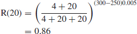
A large program is believed to contain about 300 errors and the recorded MTTF at the start of testing is 1.5 h. The testing compression factor is assumed to be 4. How much testing is required to reduce the remaining number of errors to ten? What will then be the reliability over 50 h of running?
From Eqs. (10.6) and (10.7),
Therefore
T2 = 45h
and
Δt = 382.6h
giving
![]()
10.14.4 The Jelinski–Moranda and Schick–Wolverton Models
Two other exponential-type models which have been suggested are the Jelinski–Moranda (JM) model and the Schick–Wolverton (SW) model. In the JM and SW models, the hazard function h(t) is given respectively by:
![]()
![]()
where ti is the length of the ith debugging interval, that is the time between the (i − 1)th and the ith errors, and φ is a constant.
10.14.5 Littlewood Models
Littlewood attempts to take account of the fact that different program errors have different probabilities of causing failure. If φ1, φ2, . . ., φN are the rates of occurrence of errors 1, 2, . . ., N, the pdf for the program time to failure, after the ith error has been fixed, is
![]()
where λ is the program failure rate
![]()
![]() is assumed to be gamma-distributed, that is errors do not have constant rates of occurrence but rates which are dependent upon program usage. If the gamma distribution parameters are (α, β) (equivalent to (a, 1/λ) in Eq. 2.28) then it can be shown, using a Bayes approach, that
is assumed to be gamma-distributed, that is errors do not have constant rates of occurrence but rates which are dependent upon program usage. If the gamma distribution parameters are (α, β) (equivalent to (a, 1/λ) in Eq. 2.28) then it can be shown, using a Bayes approach, that
![]()
where t' is the time taken to detect and correct i errors. From this
![]()
and
![]()
At each error occurrence and correction, λ(t) falls by an amount α/(β + t′). It is assumed that all detected errors are corrected, without further errors being introduced.
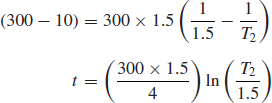
Example 10.2
A large program is assumed to include a total of 300 errors, of which 250 have been detected and corrected in 20 h of execution time. Assuming the Littlewood model holds and the distribution parameters are α = 0.005, β = 4, what is the expected reliability over a further 20 h?
From Eq. (10.12),
10.14.6 Point Process Analysis
Since a program can be viewed as a repairable system, with errors being detected and corrected in a time continuum, the method of point process analysis described in Chapter 2 can be applied to software reliability measurement and analysis.
10.15 Hardware/Software Interfaces
In software controlled systems, failures can occur which are difficult to diagnose to hardware or software causes, due to interactions between the two. We have already covered examples of such situations, where hardware elements provide program inputs. The software design can minimize these possibilities, as well as provide automatic diagnosis and fault indication. However, there are other types of failure which are more difficult, particularly when the hardware/software interface is less clearly defined.
Hardware meets software most closely within electronic devices such as processors and memories. A failure of a memory device, say of an individual memory cell which always indicates a logic state 1 (i.e. stuck at 1) regardless of the input, can cause failures which appear to be due to software errors. If the program is known to work under the input conditions, electronic fault-finding techniques can be used to trace the faulty device. There are times, particularly during development, when the diagnosis is not clear-cut, and the software and hardware both need to be checked. Timing errors, either due to device faults or software errors can also lead to this situation.
Memory devices of all types, whether optical or magnetic media or semiconductor memory devices, can cause system failures. Memory media and devices belong to the class of equipment sometimes called ‘firmware’, to indicate their interface status. Since many memory media are dynamic, that is the same data are handled in different locations at different times during program execution, firmware failures can lead to system failures which occur only under certain operating conditions, thus appearing to be due to software errors. Such failures can also be intermittent. Software and memory or microprocessor devices can be designed to protect the system against such failures. For example, the redundancy techniques described above could provide protection against some types of dynamic memory failure (other than a catastrophic failure of, say, a complete memory device). Redundancy can be provided to data or logic held in memory by arranging for redundant memory within the operating store or by providing independent, parallel memory devices. The program logic then has to be designed to store and access the redundant memory correctly, so the program becomes more complex.
10.16 Conclusions
The versatility and economy offered by software control can lead to an under-estimation of the difficulty and cost of program generation. It is relatively easy to write a program to perform a simple defined function. To ensure that the program will operate satisfactorily under all conditions that might exist, and which will be capable of being changed or corrected easily when necessary, requires an effort greater than that required for the basic design and first-program preparation. Careful groundwork of checking the specification, planning the program structure and assessing the design against the specification is essential, or the resulting program will contain many errors and will be difficult to correct. The cost and effort of debugging a large, unstructured program containing many errors can be so high that it is cheaper to scrap the whole program and start again.
Software that is reliable from the beginning will be cheaper and quicker to develop, so the emphasis must always be to minimize the possibilities of early errors and to eliminate errors before proceeding to the next phase. The essential elements of a software development project to ensure a reliable product are:
- Specify the requirements completely and in detail (system, software).
- Make sure that all project staff understand the requirements.
- Check the specifications thoroughly. Keep asking ‘what if . . .?’
- Design a structured program and specify each module fully.
- Check the design and the module specifications thoroughly against the system specifications.
- Check written programs for errors, line by line.
- Plan module and system tests to cover important input combinations, particularly at extreme values.
- Ensure full recording of all development notes, tests, checks, errors and program changes.

Figure 10.6 shows the sequence of development activities for a software project, with the emphasis on reliability. Musa (2004) and Leveson (1995) provide excellent overviews of software reliability and safety engineering. ISO/IEC90003.2004 provides guidelines for the generation of software within the ISO9001 quality system. US DoD Standard 2168 describes quality requirements for the development of software for military projects.
Questions
- Discuss the main differences between the ways in which software and hardware can fail to perform as required. Give four examples to illustrate these differences.
- Explain the ways in which software in engineering systems can be different to other kinds of system.
- What are the three principal stages in software development that can lead to errors in programs? Give one example of the type of software error that can be created in each stage.
- What is structured and modular design in the context of software? Describe the main advantages and disadvantages of these approaches.
- How can software be used to protect against hardware failures in systems that embody both? Give two examples of how software can be used to provide such protection.
- Describe the essential points to be considered in setting up a test programme for newly developed software. Include the distinction between verification and validation.
- Several methods have been postulated for predicting and measuring the reliability of software. What are the two main categories of software reliability model? Briefly describe one model in each category, and discuss their main assumptions in relation to predicting the reliability of a new program.
Bibliography
Beizer, B. (1995) Black-Box Testing, J. Wiley and Sons.
Kaner, C., Falk, J. and Nguyen, H. (1999) Testing Computer Software, 2nd edn, Wiley.
Leveson, N. (1995) Safeware – System Safety & Computers, Addison Wesley.
Musa, J. (2004) Software Reliability Engineering: more reliable software faster and cheaper (2nd edn.) Authorhouse.
Musa, J., Iannino, A. and Okumoto, K. (1987) Software Reliability Prediction and Measurement, McGraw-Hill.
Ould, M.A. and Unwin, C. (1986) Testing in Software Development, Cambridge University Press.
Patton, R (2006) Software Testing, 2nd edn, SAMS Publishing.
US DoD Standard 2168 Defence System Software Quality Program. Available from the National Technical Information Service, Springfield, Virginia.
ISO/IEC 90003. (2004) Guidelines for the Application of ISO 9001 to Computer Software.
1 Data or programs stored in some media can degrade. Magnetic media such as discs are susceptible to electromagnetic fields, or even to being closely packed for long periods. VLSI semiconductor devices can suffer changes in the voltage state of individual memory cells due to naturally occurring alpha-particle bombardment. In each case a refresh cycle will restore the program.