
STUDIO PREPARATION
The first days of production are commonly very exciting, as hopefully a team will have worked hard during the weeks preceding their entrance into the recording environment. It is important to approach the set-up stage efficiently, but without the fear of changes in the plan. The quality of the technical team’s work during tracking will potentially have the greatest impact over that of the final product, so standards should be set as high as possible. With this in mind, recordists should evaluate all the elements that may influence the result of sessions and attempt to optimise them.
ACOUSTICS
It is not uncommon for less experienced recordists to be only partially aware of the influence of acoustics over the quality of their productions. In certain cases this also seems to extend to professionals, as some engineers appear to overlook the possibility of varying the properties of the studio environment in order to achieve better results. It is arguable that the relationship between sound recording and acoustics has changed significantly since the introduction of DAWs and plug-ins, as these have made it easier for engineers to manipulate or even replace recorded material. Still, there is a limit to what may be achieved through artificial processing during editing and mixdown and few will question the value of working with strong raw materials, e.g. natural and authentic sounding recordings.
It seems advisable for those aiming to develop their recording skills to spend some time studying the fundamentals of acoustics, focusing their attention on the behaviour of sound in enclosed spaces. Although the aforementioned topic is undoubtedly complex, the knowledge of some of its basic principles may be sufficient to help recordists make simple and positive decisions in studio. As a starting point, engineers may choose to investigate the concepts of sound transmission, reflection and absorption, as this will help them to better understand what takes place in recording rooms.
When sound encounters a barrier, one or more of the following phenomena may occur:
Transmission
The energy of a sound wave can be transferred between environments, even when these are separated by a boundary. The mass and the density of the boundary influence this transfer and the magnitude of transmission is directly proportional to the amplitude (intensity) and inversely proportional to the frequency of the travelling sound wave. For these reasons, isolation is very difficult to obtain in the case of high level, low-frequency rich sounds, e.g. bass drum, bass guitar, etc.
The transfer of energy through barriers is of particular relevance to those attempting to work in residential settings, where the presence of neighbours may make the recording and monitoring of loud sources impractical or even impossible. Contrary to what some inexperienced recordists think, the sole use of absorbing materials, e.g. foam, can do little regarding isolation and may simply alter the recording environment’s frequency response negatively (through the dampening of high frequencies). A better alternative for those aiming to isolate their environment from the outside world is to increase the mass and the density of their boundaries (and their number), while aiming to decouple them from each other.
Isolation and Decoupling
The transmission of sound between environments can be minimised through decoupling. This requires a reduction in physical contact between the areas to be isolated and in many instances can only be achieved effectively through structural changes, e.g. the floating of floors, ceilings, etc. Although airborne noise is responsible for most transmission-related problems, the dampening of mechanical vibrations is very important when isolation is needed and recordists should be ready to work with materials such as neoprene rubber when aiming to stop mechanical transmission, e.g. creating platforms for amplifiers, etc.
Sound loses a lot of its energy as it travels through different media and this can be explored in circumstances where extended attenuation is needed, e.g. two barriers may be significantly more efficient in stopping sound if separated by an air gap as opposed to placed back to back.
Speaker Decoupling
Monitor pads can improve the quality of reproduced sound by reducing the interaction between speakers and the surfaces on which they rest. Such products are commonly made out of rubber and represent a small investment that may yield considerable results.
Reflections
When a sound wave meets a solid obstacle of significant size it will have some of its energy deflected and sent back in the direction of origin. Once again the composition and dimensions of the barrier will dictate how much of the energy will be redirected and how much will be transferred. This phenomenon has great importance in the case of musical content, due to resulting alterations of amplitude and timbre as direct and reflected sounds combine.
When numerous ‘versions’ of a signal (echoes) are generated in succession due to the presence of boundaries, sound waves will follow multiple paths and eventually interfere with one another. If the pre-delay gap (the time lapse between direct sound and first reflections) is small, the aforementioned interference will affect the timbre of signals noticeably (due to comb filtering).
Good sounding natural reverberation is the sum of complex reflections that occur under favourable conditions. On the other hand, non-flattering reverb, e.g. flutter echo, is almost always available, although such effect is commonly detrimental to musical recordings and, if possible, best avoided.
Negative Interference / Comb Filtering
The influence of early reflections over the timbre of sound can be demonstrated through real-time experiments. As an example, if a recordist holds a small, battery-operated speaker producing white noise and approaches a wall, a ‘phasing’ like effect will be detected (a manifestation of comb filtering). Such phenomenon illustrates why engineers should place performers away from boundaries and why they should consider the placement of reflective surfaces in the recording environment carefully, e.g. music stands, etc.
Standing Waves
The presence of parallel walls in small, enclosed spaces accounts for the pronounced occurrence of standing waves. These result from reoccurring, predictable reflections and translate into a frequency spectrum that changes in relation to position, i.e. small rooms with parallel surfaces present a very inconsistent spatial response. Unfortunately this is the reason why a lot of recordists are not able to achieve satisfying results in their home studios, as most untreated domestic rooms present peaks (resonances) and valleys in frequency response and do not offer a trustworthy critical listening position.
Standing Waves in Control Rooms
Control rooms should be free of pronounced standing waves. If the latter are not avoidable due to construction-related constraints, reflections must be ‘tamed’ and reduced to a minimum through absorption and/or diffusion. There are a few ways to assess the impact of standing waves over the sound quality of a given control room. One of the simplest procedures involves the playing and auditioning of ascending pure tones at constant levels, e.g. engineers may set up an oscillator or an instrument to play 41 Hz (E1), 44 Hz (F1), 46 Hz (F#1), etc., checking for audible inconsistencies at the critical listening position.
NB It is important to take the concept of ‘equal loudness’ into consideration during this experiment (see Appendix 3).
Resonances (Standing Waves) in Live Rooms
Although commonly described as harmful, resonances may be explored artistically in live rooms if the ‘colouring’ of an original source is desired, e.g. a ‘bassier’ production of sound from a ‘thin’ emitter. As an example, in home recording environments, a sound source may be placed in a highly resonant space such as a bathroom or a room’s corner for effect (although this should be approached with caution).
Diffusion
Diffusion is the name given to the ‘scattering’ of sound through reflections that are theoretically random in orientation, i.e. ones that do not follow a predictable travel path. This phenomenon may help to remedy the problem of comb filtering and flutter echoes, making small rooms sound more ‘musical’ or less ‘boxy’.
Diffusers
Diffusers come in different shapes and sizes. Some look very complex, e.g. skyline models, while others seem much simpler, e.g. QRDs (quadratic residue diffusers). The theory supporting the design of such devices is based on advanced mathematics and although they may seem difficult to build, recordists with a little experience in carpentry should be able to assemble a basic diffuser, which could help improve the sound quality of their listening environment.
Absorption
The energy of a sound wave may be ‘absorbed’ or transformed through friction or ‘dampening’. This justifies the use of porous materials, e.g. acoustic foam, to control the transmission of sound and numerous acoustic devices using this principle have been developed to help ‘tame’ reflections in problematic environments.
The conversion of acoustic energy into heat is most efficient when a sound wave travelling at maximum speed meets a porous obstacle. To achieve such a degree of absorption, engineers may:
• Employ a free-standing porous boundary with a thickness that matches half the wavelength of the lowest frequency to be absorbed, e.g. a 1.56 metre-thick absorber in the case of 110 Hz (A2).
• Use a thinner absorber placed at one quarter of the same wavelength away from a reflective surface, e.g. a less thick porous boundary placed at 0.78 metres from a wall in the case of 110 Hz (A2).
Both aforementioned strategies guarantee that a lowest ‘target’ sound wave and subsequently other higher-frequency waves will have an instance of maximum velocity within the absorber.
Bass Traps
Low frequencies have long wavelengths, which challenge the use of porous materials for absorption, e.g. a free-standing boundary would need to be at least 4.2 metres thick in order to absorb 41 Hz (E1) efficiently (where 4.2 metres is half the wavelength of 41 Hz).
Bass traps are devices designed to capture low-frequency waves at points of build-up, e.g. corners. As we have seen, the placing of porous materials at a distance from boundaries extends their bandwidth of absorption, allowing for smaller devices to be used.
Strategically placed bass traps can be very efficient in the control of low-frequency energy.
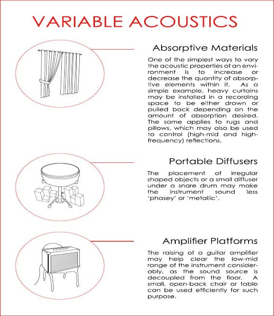
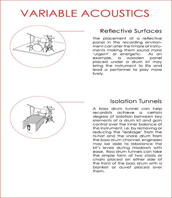
Applied Variable Acoustics
The use of variable acoustics or portable acoustic devices allows for dynamic control over the sonic characteristics of an environment.
The following pages contain simple examples of variable acoustic concepts applied in practice.
POWER AND DISTRIBUTION
The quality of power supply is a concept that is usually ignored by engineers working in well-established commercial studios, as the latter commonly invest considerable resources in the treatment of the power they utilise. The picture can be quite different in the case of recordings that take place in residential environments, where recordists may need to check and plan their access to mains supply, in order to avoid or minimise problems such as ‘hum’.
It is not the objective of this text to cover the basics of electronics theory, as many publications dedicated to the topic are readily available. What follows are simple, basic suggestions for recordists working in amateur or semi-professional studios:
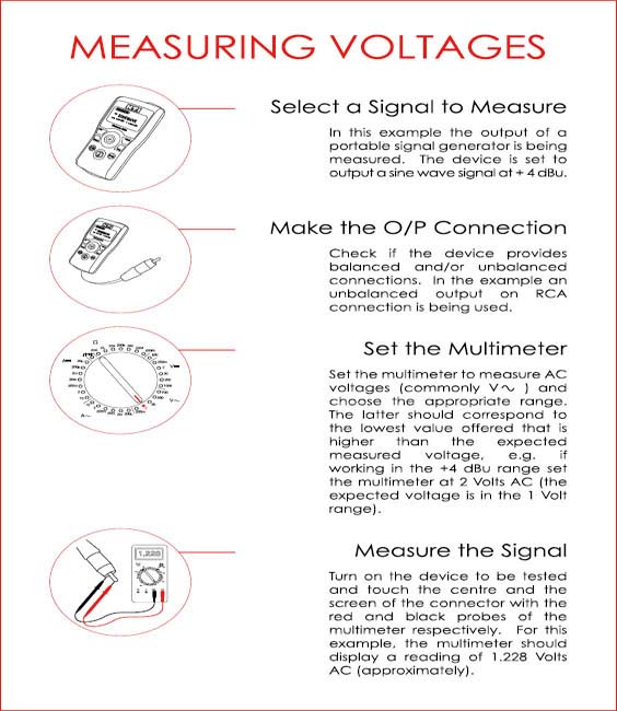
1. Measure mains power at all supply points (outlets) and ensure that values are consistent and do not fall beyond plus or minus 10 percent outside the stated requirements of the equipment being used, e.g. if a microphone preamplifier is rated at 240 Volts the mains supply should not approach the limits of 216 Volts and 264 Volts.
NB NEVER attempt to perform step 1 if you have not been trained to use a voltmeter or if you do not own a standalone safe power outlet tester.
2. Ensure all audio-related equipment shares the same path to the ground (not necessarily the same outlet) and that such path is not shared by non-audio-related devices, such as light fixtures, portable heaters, kitchen utensils, etc.
NB Simply reduce the use of non-vital, peripheral electrical devices if the electrical wiring of the recording environment is not clear.
3. Utilise surge-protection supply devices, e.g. specialised high-quality power strips, to feed all sensitive audio equipment, e.g. computers, audio interfaces, etc. (this may help avoid ‘clicks’ or ‘spikes’ in recordings).
The following page contains a graphic description of the process of measuring voltages.
EQUIPMENT ALIGNMENT
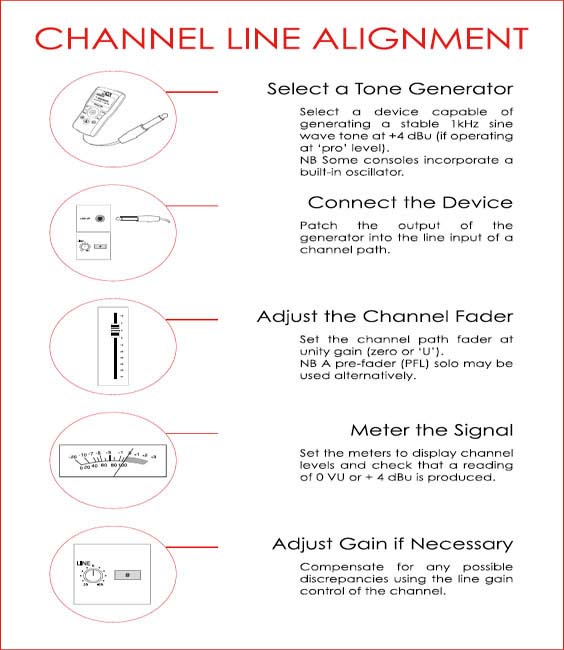
Following power-up, the different elements of the recording chain must be aligned to ensure they will interface with each other in a coherent, optimised fashion.
Analogue Alignment
The starting point of strictly analogue alignment is the establishing of standard operating levels and clipping points for all the elements in the audio path. In possession of this information, recordists can subsequently determine the headroom of all devices and set the ‘standards’ for that signal chain, i.e. the lowest clipping point should be taken as a path’s ‘ceiling’ (unless distortion is desired). As an example, if a chain incorporates a console with a clipping point of + 18 dBu and a tape-based recorder that ‘clips’ at + 12 dBu, the latter value should be used as the ceiling of the system, i.e. operators should avoid boosting signals beyond + 12 dBu.
Digital Alignment
Digital alignment is the simplest of all three processes. Here, operators must only ensure that a common ‘average’ or reference level is selected and utilised consistently, which in some cases may require a simple change in DAW settings (preferences).
NB As far as the choice of the aforementioned reference level is concerned, two main standards are commonly used:
• EBU R68 = – 18 dBFS
• SMPTE RP155 = – 20 dBFS.
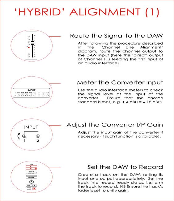
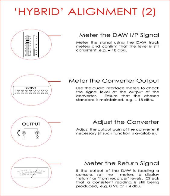
Hybrid (Analogue / Digital) Alignment
The alignment process is somewhat different when digital devices are used alongside analogue equipment. In digital audio technology, the fixed reference 0 dBFS does not represent an average, but a maximum value that must not to be exceeded (unless gross digital distortion is desired). This ‘peak’ value must therefore be equated to the maximum dBu or dBV value that can be handled by the analogue devices in the chain, without the production of objectionable distortion.
In hybrid alignment, the figures that correspond to the ‘average’ operating level and subsequently the headroom may in most circumstances be set by the user, i.e. professional converters allow for operators to set the dBFS level that will correspond to a counterpart analogue standard operating level, e.g. – 18 dBFS may be set to match + 4 dBu (1.228 Volts RMS) or 0 dBu (0.775 Volts RMS) on conversion.
Decibels
A decibel value is an expression of a ratio, or a comparison, in logarithmic form. Logarithms are used in engineering as they allow for a simpler, more manageable representation of very vast ranges. As an example, the human ear is capable of ‘safely’ handling pressure spanning approximately between 0.00002 and 63.25 pascals or between 0 and 130 dBSPL. This substantial (1.265 x 10^6) range seems more conveniently represented in dBSPL form, since the latter allows for faster communication and the easier graphic display of quantities, e.g. through cartesian plane graphs.
Standard Operating Levels
The concept of standard operating level (SOL) is used to describe a recommended average level at which equipment should run in order to operate well above the noise floor and without producing objectionable distortion. The following are industry standard operating levels:
Professional Equipment
0 VU = + 4 dBu = 1.228 VRMS
Semi-Professional Equipment
0 VU = – 10 dBV = 0.316 VRMS
NB Two other standard operating levels, ‘broadcasting’ (commonly + 8 dBU) and ‘hi-fi’ (– 10 dBu) are also used in the audio industry, although these may vary geographically.
PREPARING THE DAW SESSION FILE
Following the alignment of the recording equipment, technicians should prepare the DAW project file. The session plan should be consulted at this stage as it should specify:
• If a click track is necessary (and its tempo)
• If a backing track or sequence will be used
• Whether samples will be incorporated into the production.
Alternatives to Click Tracks
Some drummers may find the sound of a traditional click track uninspiring or annoying. In such cases, session engineers may:
• Add a beat-related, e.g. crotchet, delay to the sound of the drums in the cue mix only (which will help drummers detect when they are drifting out of time).
• Use a looped sample of a steady percussive ‘groove’, e.g. congas playing a few bars, as a guide to help the drummer keep a steady pulse.
• Use a track of cowbell, woodblock, tambourine, etc. played ‘live’.
Time-Stretching and the Click-Track
Whenever possible, operators should record the audio signal used for time keeping with their relevant sessions, as such files may be invaluable in the case of a DAW or platform change (which could require the remapping of tempo, etc.). When using advanced time stretching, e.g. Elastic Audio, Flex Time, etc., recordists can easily alter the tempo of audio files used for time reference, by making these ‘tick-based’ and not ‘sample-based’.
Sample and Tick-Based Timescales
Current DAWs allow for the position (or ‘address’) and length of regions to be given in samples or in bars, beats and tick values. When a sample-based timescale (timebase) is used, audio regions are positioned according to sample value, e.g. in 44100 Hz, a region placed at ‘address’ 44101 will play one second after the start of the session and this position will remain fixed regardless of tempo changes.
A tick-based timescale allows for the placement and speed of playback of MIDI and ‘elastic’ or ‘flex’ time audio regions to be automatically updated according to tempo, e.g. a region placed on the second quaver of the third beat of bar four and lasting for two bars will play at its given music-related position and for its full length at any selected tempo (speeding up or slowing down accordingly). In a tick-based scale, region positions are described in bars, beats and ticks, which correspond directly to the following musical note values:
• Semibreve (whole note) = 3840 ticks
• Minim (1/2 note) = 1920 ticks
• Crotchet (1/4 note) = 960 ticks
• Quaver (1/8 note) = 480 ticks
• Semiquaver (1/16 note) = 240 ticks
• Demisemiquaver (1/32 note) = 120 ticks.
Using a previous example, in common time or 4/4 and with the DAW ‘division’ set at 1/4 note, a region placed on the second quaver of the third beat of bar four will have the address 4|3|480.
Session File Templates
Recordists can benefit from the use of templates by not having to create multiple tracks, assign track inputs and outputs, create busses (cues, effects), assign buss inputs and outputs, etc. for each song to be recorded. DAWs allow users to save session file templates, which can be very useful when numerous songs with similar set-ups will be recorded in succession.
Auto-Backup
Recordists should enable ‘auto-backup’ or any other automatic background saving function of their DAW as soon as possible and ideally before sessions. This may allow some work to be salvaged in the case of an application or computer crash.
Labelling Folders and Files
It is important for DAW users to be sensible and remain consistent when labelling folders and files. As a suggested approach, folders
Labelling Folders and Files (continued)
and sub-folders may be organised in the following hierarchical manner:
1. Main client, e.g. a record label or producer (top folder)
2. Artist (sub-folder of ‘Main client’)
3. Album or project (sub-folder of ‘Artist’)
4. Song (sub-folder of ‘Album’), e.g. Song X
5. Session Files (sub-folders of ‘Song’), e.g. Song X_01JAN13_A or Song X_010113_A (following the format Song_Date_Version).
Slating the Recorder
It is important to document the operating level used for each recording session, as this may vary between productions. The process of ‘slating’ the recorder, i.e. the recording of tones at reference level, is arguably seen as less important since the introduction of digital recording, although this procedure still plays a vital role in the alignment of devices during the subsequent stages of production.
In cases where slating is not possible, e.g. if an oscillator or signal generator is not available, DAW operators should at least note down the selected standard for each session, e.g. + 4 dBu = – 18 dBFS.
Audio File Types
It is recommended that recordists work with or generate (data) uncompressed audio files with wide support, i.e. files that are known for their resilience and mobility. Currently, the Broadcast Wave (.bwf) format is considered to be the most universal, being supported by a variety of platforms and applications. Other acceptable file types include: .aiff and .wav, while compressed or not currently supported file types, such as .mp3, .m4a, .m3u, .wma, .ra, .sd, .sd2, etc., should be avoided during production.