
Chapter 3. Subtask 1: Light an LED
We’ll start with Subtask 1 and assemble a small circuit to light a single LED. The components you will need include:
1 MintDuino—assembled (see Chapter 1 for assembly instructions)
1 9V battery
1 FTDI adapter, such as the FTDI Friend (see http://www.makershed.com/ProductDetails.asp?ProductCode=MKAD22)
1 USB cable (A to mini-B type)
Plus, you’ll need the following components, all of which are available in the Mintronics: Survival Pack:
1 LED (one red and one green LED come with the Survival Pack, but you can use any color you have handy)
1 mini breadboard
1 9V battery connector
1 resistor, 100 ohm (minimum)
2 jumper wires
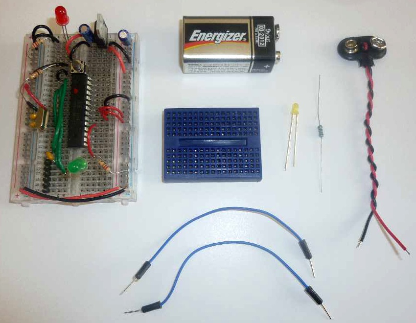
Figure 3-1 shows the components required to assemble Subtask 1. Later, you’ll use the FTDI adapter to upload the sketch to the MintDuino.
Start Building
You’ll start the assembly of Subtask 1 by inserting the LED and resistor (refer to this resistor as RES1 for all subtasks) into the mini breadboard, as shown in Figure 3-1.
Before you continue, there are a few things you need to know when using the mini breadboard:
The mini breadboard does not have letters or numerals to label the various rows and columns (which the MintDuino’s breadboard does have).
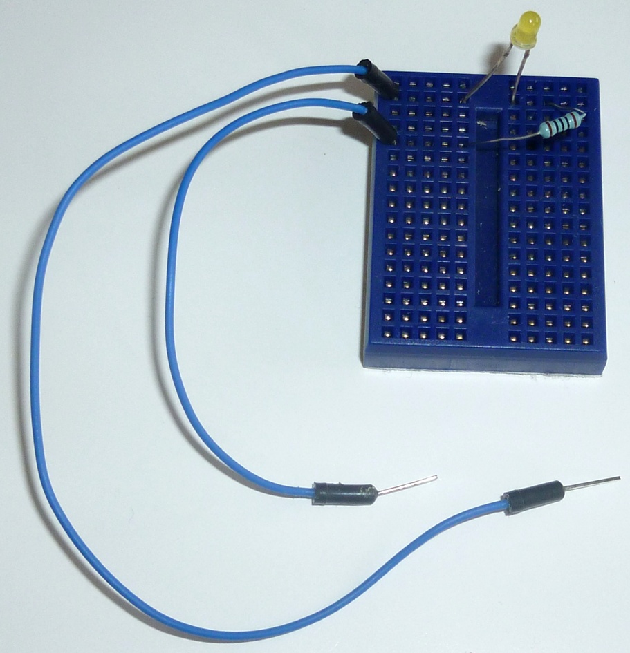
When wiring, rotate the mini breadboard so that it is taller than it is wider (as seen in Figure 3-2); with this orientation, each row is broken into two segments of five holes.
The five holes in each segment share a common connection point; when inserting components, make certain that leads are inserted in different segments and not in the same grouping of five holes or the component will be shorted.

Take note that the LED has one leg that is shorter than the other. The longer leg is referred to as the anode or + lead (positive); and the shorter leg is referred to as the cathode or – lead (negative). When connecting an LED to a circuit, you must remember to connect the + lead to the voltage/supply side of a circuit and the – lead to the GND (ground) side of a circuit.
Because you haven’t yet wired up power to the MintDuino, just remember (or jot down a note here) where the longer + lead of the LED is located. If you’re following along with the included images, you’ll want to insert the longer + lead closer to the left side of the mini breadboard; this side will be closest to the MintDuino once it is finally connected to the mini breadboard.
Note
One useful way to remember how an LED is inserted into the mini breadboard is to insert the longer (+) lead closer to the MintDuino. If you consistently use this method, you’ll always be able to look at an inserted LED and determine which lead is the anode and which is the cathode.
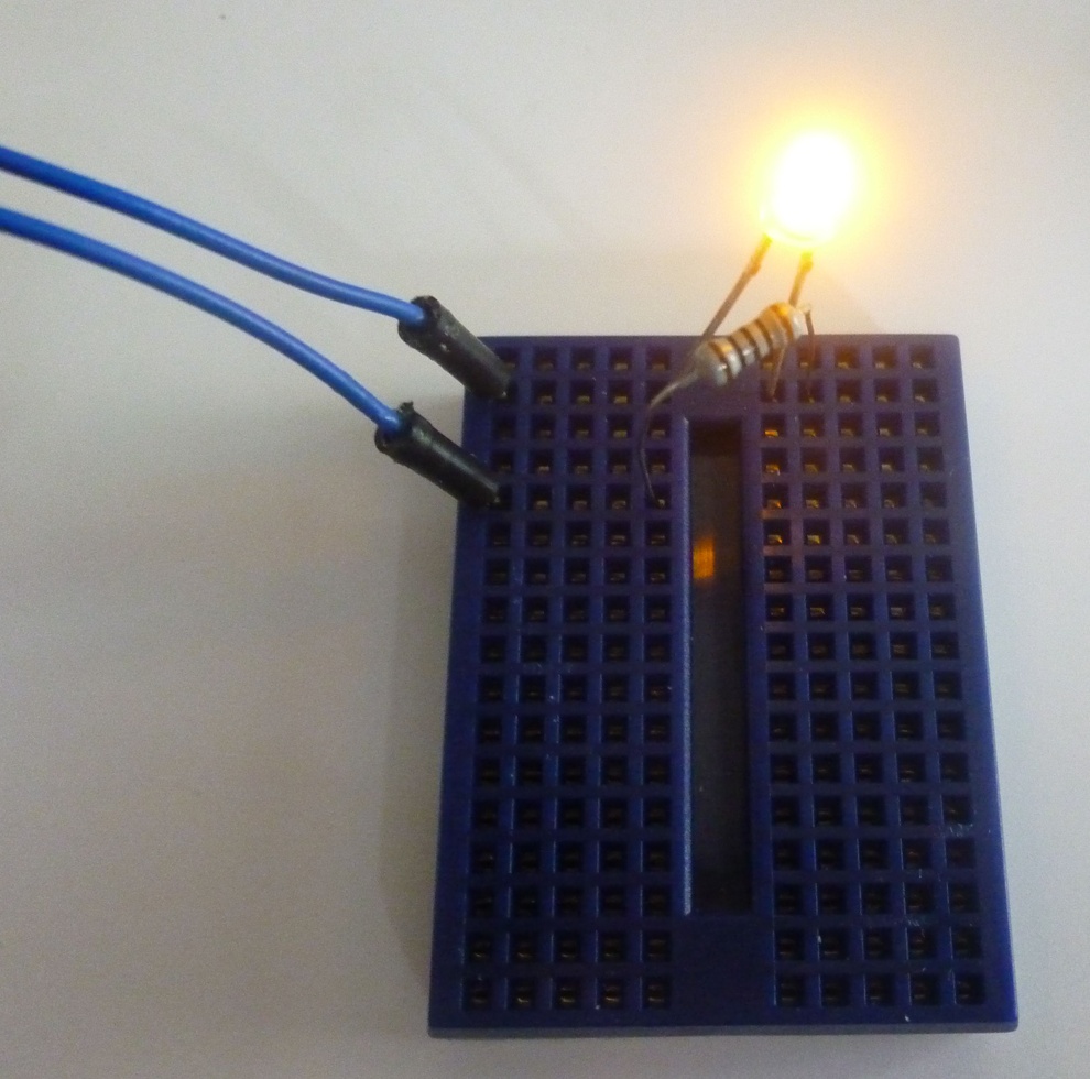
I’ve also inserted RES1 so that one of its leads shares a row with the cathode (–) lead of the LED. Notice in Figure 3-2 that RES1’s other lead is inserted into an empty row on the mini breadboard just below the LED’s anode lead.
Next, you’ll use two jumper wires to connect the mini breadboard to the MintDuino. Insert one jumper wire into the same row as the LED’s anode lead. Insert the other wire into the same row as RES1’s non-shared lead (the lead not shared by the LED’s cathode lead). This is shown in Figure 3-3. Black wire is often chosen when making connections to GND and red wire is typically selected for making connections to voltage/power; feel free to use these colors for the jumper wires if you have them (or if you have the Survival Pack), but it is not required.
Now you’ll connect the two jumper wires to the MintDuino. If you’ve built your MintDuino based on the building instructions in Chapter 1, you’ll want to connect the jumper wire connected to the LED’s anode (+) lead to Pin 13 on the ATmega 328 chip. This corresponds to Row 21 on the MintDuino (again, if you’ve taken care to wire it up exactly as the instructions specify). You can plug that jumper wire into any free hole between a and e on Row 21.
Note
Pin 13 corresponds to Digital Pin 7—this information will be required shortly when we write the program to test the LED.
Plug the other jumper wire from the LED’s cathode (–) into any hole on the GND column of the MintDuino. Double-check this and make absolutely certain that you’ve connected it to a GND column and not the PWR (5v or 3.3v) column.
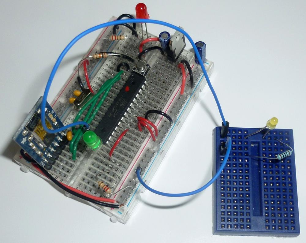
Figure 3-4 shows the two jumper wires now connecting the mini breadboard to the MintDuino.
Upload Your First Sketch
Now it’s time to upload the Subtask 1 program (sketch). You can download this sketch from http://examples.oreilly.com/0636920020882, or simply open your Arduino IDE and enter the following sketch/code:
// MintDuino NoteBook 1 – Subtask 1
int ledPin = 7; // Digital Pin 7 for LED anode connection
int ledWaitMin = 2000; // Set minimum wait time to 2000 milliseconds
void setup() {
// use noise on pin 1 to generate a random number
randomSeed(analogRead(1));
pinMode(ledPin, OUTPUT);
}
void loop() {
// add random time of 0-5 seconds
int ledWait = ledWaitMin + random(5000);
// three fast blinks
for (int count = 0; count < 3; count++) {
digitalWrite(ledPin, HIGH);
delay(250);
digitalWrite(ledPin, LOW);
delay(250);
}
delay(ledWait); // random amount of time passes
digitalWrite(ledPin, HIGH);
delay(2000); // wait 2 seconds after random lighting
digitalWrite(ledPin, LOW);
delay(5000); // wait 5 seconds before resetting
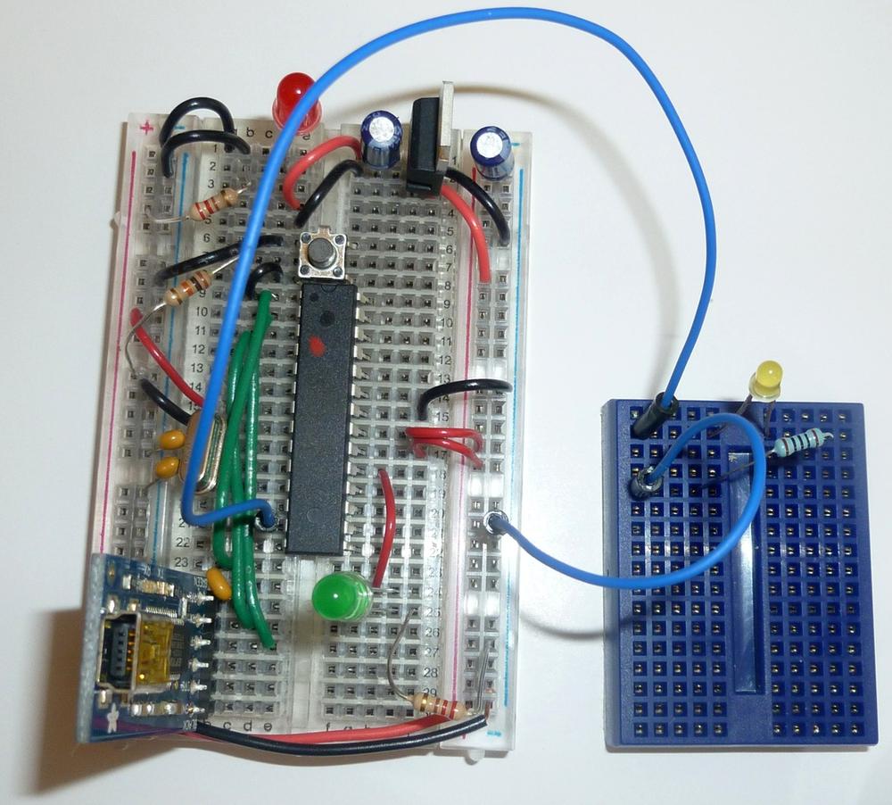
}Connect the FTDI Friend (or other FTDI adapter) to your MintDuino as seen in Figure 3-5. This connects your computer to the MintDuino so that you can upload the sketch. Remember that you’ll need to provide power to the MintDuino using the 9V battery!
After uploading the sketch to the MintDuino, leave the USB cable plugged into the FTDI/MintDuino and you should see a quickly flashing LED on the mini breadboard, as shown in Figure 3-6.
Leave the circuit wired up, as you’ll use it again with Subtask 2, but unplug the USB cable that connects the FTDI/MintDuino to your computer.