
Chapter 5. Subtask 3: Light an LED with a Pushbutton
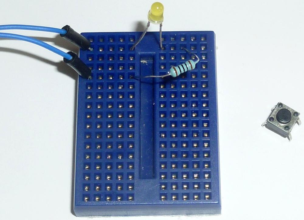
Subtask 3 will add to the same circuit you assembled for Subtasks 1 and 2 by introducing the single pushbutton component to the mini breadboard, as seen in Figure 5-1. Subtask 3 will require the following additional components beyond what you’ve already assembled. All of these are available in the Mintronics: Survival Pack:
1 resistor, 100 ohm (minimum)
1 red jumper wire (3 inches in length)
3 blue jumper wires (make two of them 2 inches in length, and one of them 4 inches; they can be any color except red or black)
1 pushbutton
Note
By the end of this Subtask, you will probably have exhausted the supply of jumper wire that came with the Survival Pack, and will need to dip into your jumper wire kit if you haven’t already.
Add the pushbutton to the mini breadboard by inserting it so that the distance between the two top legs is a single hole (on a single row) and the distance between a top and a bottom leg has two holes between it (spanning four rows altogether). A close-up of this can be seen in Figure 5-2.
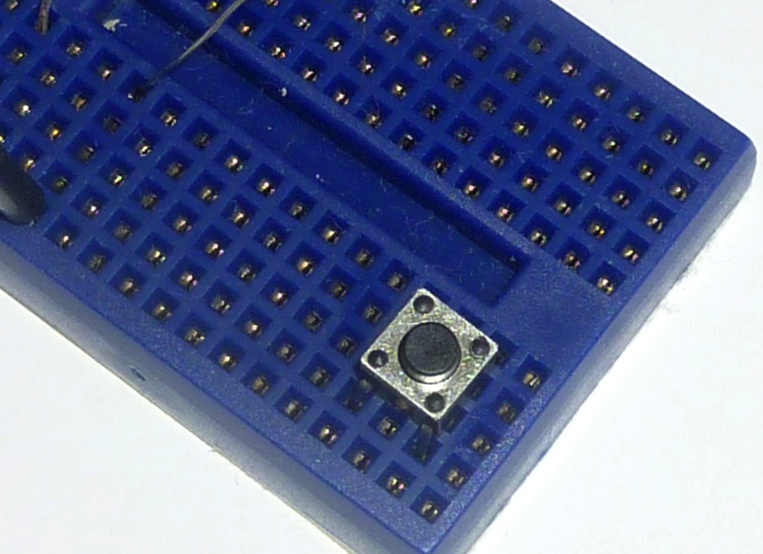
Figure 5-3 shows the pushbutton inserted into the mini breadboard. Make certain to leave the leftmost hole open on the top and bottom row where the pushbutton is inserted. (These will be used to add jumper wires.)

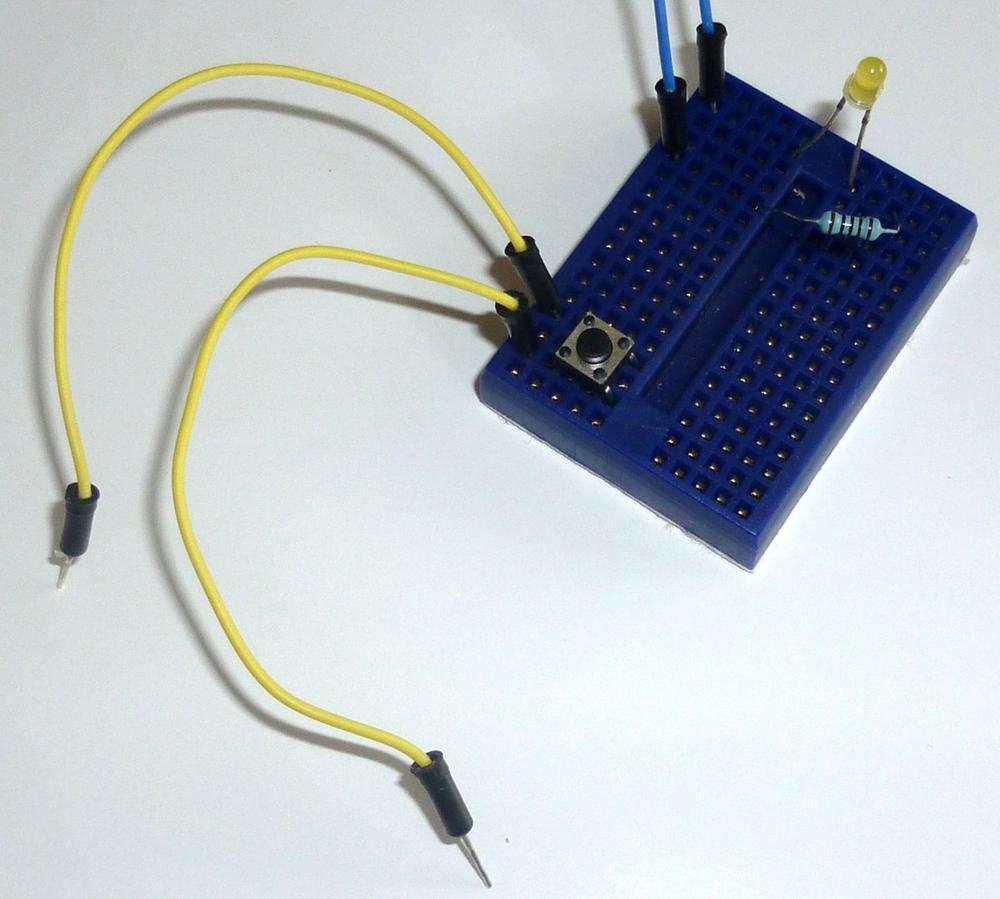
Connect two jumper wires to the pushbutton, as shown in Figure 5-4. One jumper wire is inserted in the first hole at the top row of the pushbutton and the second jumper wire is inserted in the empty bottom row of the mini breadboard.
Next, add a single 100 ohm resistor (this resistor will be referred to as RES2) to the mini breadboard, as shown in Figure 5-5. This resistor (RES2) will have one of its leads inserted into the row where the first resistor (RES1) is inserted, and the jumper wire goes to GND. The other lead for RES2 can be inserted in a row just above the pushbutton.

As shown in Figure 5-6, insert the top jumper wire of the pushbutton into the row containing only a RES2 lead (not the row that shares GND with RES1) and insert the bottom jumper wire of the pushbutton into the bottom (empty) row of the mini breadboard (which will serve as a +5V supply for the mini breadboard).
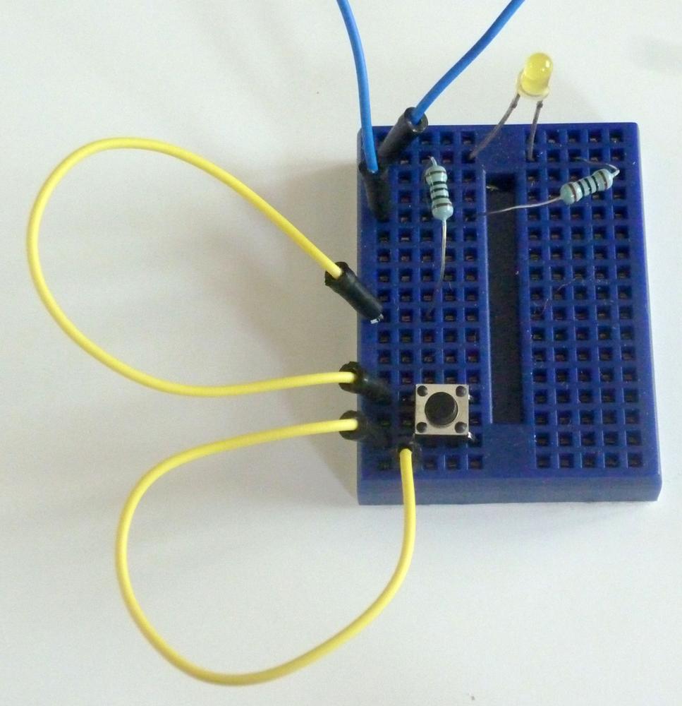
Finally, add two more jumper wires. Insert the red one into the bottom row of the mini breadboard and connect it to +5V on the MintDuino—we’ll call this the JUMPV. Insert the other jumper wire where the pushbutton’s top jumper wire and RES2 are inserted. Then connect this new jumper wire to Digital Pin 4 (or Pin 6 on the ATmega chip)—we’ll call this JUMP4. This corresponds to Row 14 on the MintDuino (only if you’ve taken care to wire it up exactly as the online instructions specify). You can plug that jumper wire into any free hole between a and e on Row 14. Both of these new jumper wires can be seen in Figure 5-7.

Light the LED
Now you will program the the LED to light up after the pushbutton is pressed. You can download the program for Subtask 3 online at http://examples.oreilly.com/0636920020882 or simply enter the code below into the Arduino IDE:
// MintDuino NoteBook 1 – Subtask 3

int ledPin = 7; // Digital Pin 7 for LED anode connection
int button = 4; // Use pin 4 for the button

void setup() {
    pinMode(ledPin, OUTPUT);
    digitalWrite(ledPin, LOW);
}

void loop() {
   int state = digitalRead(button);
   if (state == HIGH) { // determine if button is pressed or not
     lightLED();        // if it is, light the LED
   }
}

void lightLED(){ // only called when the button state is HIGH (pressed)
  digitalWrite(ledPin, HIGH);
  delay(1000);
  digitalWrite(ledPin, LOW);
}
Upload the sketch to the MintDuino and the following will occur:
The LED will not light (at first) as it waits for the button to be pressed.
The program will loop forever, waiting for the button to be pressed.
When you press the button, the
statevariable is set toHIGH.If
stateisHIGH, thelightLEDfunction is called.When the
lightLEDfunction is called, the LED stays lit for 1 second and then turns off.The program waits for the button to be pressed again.
Now we’re getting close. We know how to light an LED, create random time before the LED lights up, and we know how to wire up a button to light up the LED. But to make this a real game, there must be at least two opponents, and that means adding a second button to the mix…which is exactly what we’ll do in Subtask 4.
Note
If the LED is not lighting up when you press the pushbutton, check your wiring. The pushbutton must be connected to +5 volts—check that a jumper wire (JUMPV) is connecting the pushbutton to the bottom row of the mini breadboard that is supplying the voltage.
Also verify that the other jumper wire leaving the pushbutton shares a row with RES2 and JUMP4 on one end, and is inserted into pin 6 on the ATmega chip on the other end.