
Chapter 1. Build a Mintronics: MintDuino
The MintDuino is perfect for anyone interested in learning (or teaching) the fundamentals of how micro controllers work. It will have you building your own micro controller from scratch on a breadboard, and then easily programming it from almost any computer via the Arduino programming environment.
Unlike pre-built micro controllers, the MintDuino demonstrates the specific relationship between the wires, resistors, capacitors, and integrated circuits that enables you to program the micro controller from your computer. After building the MintDuino, you’ll have a much better understanding of how micro controllers work, and how electronics can interact with the physical world. This chapter explains how to assemble the MintDuino; in Chapter 2, you’ll learn how to create a simple game with it.
Build the Power Supply
Start building your MintDuino by adding the 7805 power regulator. This converts the 9v power to 5v power that the ATMega can use. Insert the 7805 into column “i” on the breadboard and rows 1, 2, and 3. The metal heatsink should be facing the right (or column “J”). Now we are going to add two 10 μF capacitors to the power regulator:
I like to trim the leads down so they don’t stick so far out of the breadboard. One lead is longer than the other. The long lead is the (+) lead and the short one is the (-) lead. If you trim it, make sure to keep the lengths different lengths so it’s easy to identify the (+) and (-) leads.
Take the first capacitor and insert the (+) lead into “g1” and the negative lead into “g2”. Easy!
Take the other 10 μF capacitor, and insert the (-) lead into row 1 of the (-) power rail of the breadboard. Insert the (+) lead into row 1 of the (+) rail of the breadboard.
Now lets get some regulated power over to the power rails of the breadboard. Start by stripping the ends of one piece of red wire cut to approximately 1/2” long. Insert the wire from the (+) rail of the breadboard to “j3” of the breadboard. Next, strip the ends of one piece of black wire cut to approximately 1/2” long. Insert the wire from the (-) rail of the breadboard to “j2” of the breadboard. Your breadboard should look like Figure 1-1

Now it’s time to add the power LED. Start by cutting down the leads, just as you did on the capacitor. Make sure to keep the long one (+) longer than the short one (-)! Now you can insert the red LED into the breadboard: the longer lead (+) goes into “d2” and the negative (-) goes into “d1”. Let’s get the power distributed around the board and to the LED:
Start by cutting one red wire, approximately 1/2” long and one black wire, approximately 1/2” long. Strip both ends of each wire.
Insert the red wire from “f1” to “e4”, and the black wire from “f2” to “e5”.
Cut another piece of black wire about 1/2” long (from here on out, I’m going to stop reminding you to strip each end, so make sure you do it) and insert it from the (-) rail of the breadboard and “b1”.
While we are here, lets add a 220 Ohm resistor (red, red, brown) from the (+) rail of the breadboard to “b2”. This will limit the amount of current that goes into the LED, and keep it from burning out.
Lastly, cut (1) piece of red and black wire about 1 1/2” long and connect the right side rails together. Remember to connect (+) to (+) and (-) to (-). Your breadboard should look just like Figure 1-2

Now we can power it up! Connect the battery clip’s red wire (+) to “d4” and the black wire (-) to “d5”. Connect a 9v battery and the red LED should light up. Your breadboard should look just like Figure 1-3.
Warning
If the LED doesn’t light up, disconnect the battery immediately and double check the wiring. Take the circuit apart if necessary and start from the beginning. If the LED doesn’t work at this point, nothing else will.

Now you have a nice 5V regulated power supply from a 9V battery. Your ATMega will thank you for it! OK, enough fun. Unplug the battery and let’s get started with the micro controller.
Power the Microcontroller
Now it’s time to connect power to the ATMega 328 chip (also known as an integrated circuit or IC). This is the brains of your MintDuino. It combines a microprocessor, flash memory, RAM, and digital as well as analog inputs and outputs into a single chip known as a microcontroller. It’s also the most fragile part, so make sure you’ve disconnected the battery before you do anything. The ATMega has a small “U” shaped notch on one end. This notch lets you know where pin 1 is on the chip. If you hold the chip vertically, with the notch on top, pin 1 is directly to the left of this notch. Insert the IC so the notch is pointing towards the power supply you just built, and so that pin 1 goes into “e9” on the breadboard.
Note
You may need to bend the pins in a little bit so they don’t flare out too much. Don’t use a lot of force to insert the IC or you may damage the pins.
With the ATMega inserted, you should insert the 16 MHz clock crystal, which controls the speed at which the microcontroller executes instructions:
Insert the crystal into the breadboard at “b17” and “b18”. It’s not polarized, so orientation isn’t important: you can insert it either way.
The crystal needs some capacitors to work properly. The two 22pF capacitors (marked “220”) are not polarized either, so their orientation does not matter.
Insert one 22 pF capacitor so one pin goes into the the ground rail of the breadboard and the other into “a17”.
Insert the other 22 pF capacitor with one pin into the the ground rail and the other into “a18”.
While we are working on this part of the breadboard, let’s connect a ground connection to the microcontroller: cut a 1/2” piece of black wire and connect the ground rail of the breadboard to “a16”.
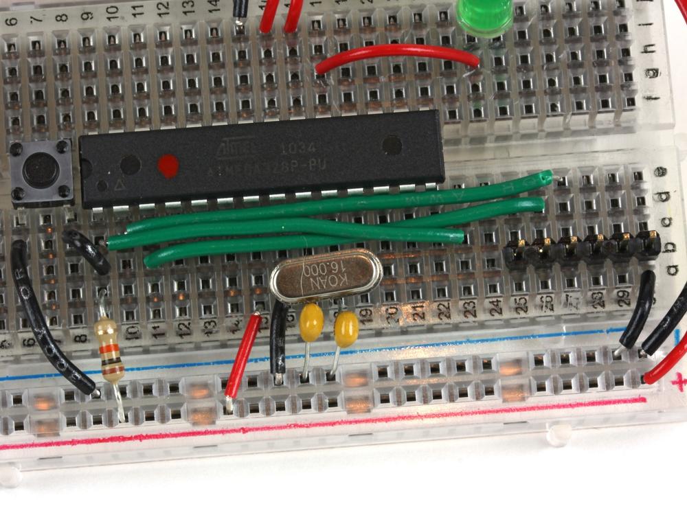
At this point, the center of your breadboard should look like Figure 1-4.

Now you’re ready to connect the positive rail of the breadboard to the microcontroller:
Cut 3 pieces of red wire, all of them about 1/2” in length, and one black wire 1/2” in length.
Use one red wire to connect the (+) rail of the breadboard to “j16”.
Use another piece of red wire to connect the (+) rail of the breadboard to “j17”.
Use one black wire to connect the (-) rail of the breadboard to “j15”.
Back to the other side of the board (by the crystal). Connect the remaining red wire from the (+) rail to “a15”.
Let’s wire up the green status LED, which will help us know whether everything is working properly. You can trim the LED’s leads if you’d like (this will make it fit the board more snugly), but remember to keep the long lead longer than the short lead:
Cut one piece or red wire about 3/4” long.
Insert the longer lead of the LED (+) into “i24” and the shorter lead (-) into “i25”.
Next connect the (-) ground rail of the breadboard to “j25” using a 220 Ohm resistor (red,red,brown).
Connect “h24” to “h18” with the red wire.
When you’re done, the breadboard should look like Figure 1-5. Now we’re ready for another test: connect the battery to the board as you did earlier, making sure you connect red to red and black to black. The red power LED should light up immediately, followed by the green LED. The green LED will then start blinking. This is because a simple “blink” program has already been uploaded to the ATMega. If the LEDs don’t light up, immediately disconnect the power, and check all your connections again.
Note
Technically, you now have an LED connected to Analog “pin 13” of the Arduino, which is the same pin used by a standard Arduino’s onboard LED. However, this is not actually pin 13 of the ATMega. The Arduino development environment uses a separate pin numbering scheme (it has a set of digital pins numbered 0 through 13 and a set of analog pins numbered 0 through 5). We’ll go over the pins in the last step of the build.

Getting Ready to Program
Now you’re ready to add some components that you’ll need before you can program the MintDuino. Let’s start with the reset button:
Cut one piece of black wire about 1” in length.
Connect the ground rail (-) of the breadboard to “d6”.
Cut another piece of black wire about 1/2” in length and connect it from “d8” to pin 1 of the ATMega at “c9”
Now press the button into the breadboard. It only fits one way, so make sure the pins all line up properly (if it feels like you’ll have to force it, turn it 90 degrees and try again). The four leads of the button will fit in “e6”, “e8”, “f6”, and “f8”.
Connect “b9” to the (+) rail of the breadboard with a 10k Ohm resistor (brown,black,orange).
You’re almost there; check out Figure 1-6 to see how your breadboard should look now.

Next, you need to wire up the six-pin programming header (only four pins are used). This doesn’t connect to the microcontroller’s traditional programming pins, but to Ground (-), the microcontroller’s reset pin, as well as its two UART (serial port) pins, TX and RX. Unlike other microcontroller environments, Arduino is programmed over a serial connection, which is why you can use a USB to TTL serial converter such as the FTDI adapter recommended in What You Need.
Start by using a pair of pliers to adjust the pins (gently) to be centered in the plastic rail, as shown in Figure 1-7. By centering the pins it makes it much easier to plug in the FTDI adapter later.
Once they are centered, insert the six-pin header in column “b” from “b25” to “b30”. Now you’re ready to wire up the programming pins.
Cut three lengths of green wire (color may vary) approximately 2” each.
Connect one wire from “d10” to “e27”.
Connect the second wire from “c11” to “d26”.
Connect the third wire from “d9” to “c23”.
Next, add the 100 nF capacitor (marked 104 on one side and K1K on the other) from “c25” to “b23”. It isn’t polarized, so you can insert it either way.
The final step is to add a 1/2” piece of black wire from “a30” to the ground rail (-) of the breadboard. Figure 1-8 shows the completed connections.

You’re all done! Your finished MintDuino should look like Figure 1-9. (Looks a bit like a scorpion, eh?) Now you’ll be ready to program the ATMega chip when the time comes in Chapter 3.
