Chapter 6
Working with Consultants
Whether you work on large or small projects—residential, commercial, or industrial building types—collaboration is an almost certain aspect of the workflow you will encounter when implementing BIM. This chapter discusses important considerations for interdisciplinary coordination as well as the tools within Autodesk® Revit® software to help you manage the process. This chapter covers aspects of collaboration solely utilizing the Revit platform, and Chapter 7, “Interoperability: Working Multi-platform,” focuses on collaborating with other software programs.
In this chapter, you’ll learn to:
- Prepare for interdisciplinary collaboration
- Collaborate using linked Revit models
- Use Copy/Monitor between linked models
- Run interference checks
Preparing for Collaboration
Working alone in the Revit environment will deliver measurable increases in productivity, quality, and consistency; however, the true benefit of building information modeling (BIM) is the ability to effectively collaborate between design disciplines, share model data with contractors, and deliver useful information to facility operators.
The difference between these working paradigms has been described as lonely BIM versus social BIM. Lonely BIM can be referred to as the use of isolated BIM techniques for targeted tasks such as architectural design or structural analysis. Social BIM is the act of sharing model data between project stakeholders in order to enhance collaboration while developing a building design. The importance of increased efficiency in collaboration is the underpinning for the goals set forth by organizations such as buildingSMART International (www.buildingsmart.com) or the UK’s BIM Task Group (www.bimtaskgroup.org).
The ability to support high-quality information exchanges necessitates the proper use of 3D models and nongraphic data in a highly collaborative environment. Although we will be discussing collaboration solely within the Revit platform in this chapter, the buildingSMART Alliance and the National BIM Standard (NBIMS-US) stress the need for open interoperability between BIM applications.
Once a project team decides to participate in social BIM—either through desire or the requirements of a client—they must decide how to collaborate with BIM in a manner that is useful to all constituents throughout the project life cycle. Whether your client requires it or not, you should develop a BIM execution plan in order to set clear expectations related to the use of BIM.
The buildingSMART Alliance (www.buildingsmartalliance.org)—in an effort sponsored by the Charles Pankow Foundation, the Construction Industry Institute, Penn State Office of Physical Plant, and the Partnership for Achieving Construction Excellence (PACE)—has created a BIM Project Execution Planning Guide and template for a BIM Execution Plan. You can find this information at the Penn State Computer Integrated Construction (CIC) website: http://bim.psu.edu.
One of the most critical parts of a BIM execution plan is the definition of the project goals and uses of BIM to achieve the stated goals. If you are just beginning your implementation of Revit software, you may be using it to create 3D visualizations, or perhaps you are attempting to increase your drafting productivity. Defining clear and concise reasons for implementing BIM on each project will help you define where to concentrate your modeling efforts. According to the buildingSMART Alliance, “[A] current challenge and opportunity faced by the early project planning team is to identify the most appropriate uses for Building Information Modeling on a project given the project characteristics, participants’ goals and capabilities, and the desired risk allocations.” A listing of the common uses of BIM along with potential value opportunities and required resources is also available on the Penn State CIC website.
According to the American Institute of Architects’ “Integrated Project Delivery: A Guide,” a BIM execution plan “should define the scope of BIM implementation on the project, identify the process flow for BIM tasks, define the information exchanges between parties, and describe the required project and company infrastructure needed to support the implementation.” To be clear, the development of such a plan does not imply the application of integrated project delivery (IPD). IPD is “a project delivery approach that integrates people, systems, business structures and practices into a process that collaboratively harnesses the talents and insights of all participants to optimize project results, increase value to the owner, reduce waste, and maximize efficiency through all phases of design, fabrication, and construction.” For the purpose of this chapter, we will consider only the collaboration and coordination between members of a project design team, not the interactions with a client or contractor.
For additional reading on IPD, refer to these sources:
- Integrated Practice/Integrated Project Delivery: www.aia.org/ipd
- Whole Building Design Guide: www.wbdg.org
- IPD and BIM white papers by Ted Sive: www.tedsive.com
Managing the Coordination Process
The coordination process in a Revit environment begins with linking multiple files together to form a composite view of your building project. Even though smaller projects might be coordinated within a single Revit project file, most moderate to large projects will be designed by multiple disciplines or trades working in different offices. A project can be divided in many different ways to meet a variety of workflow requirements. Most often, each discipline will develop at least one separate Revit project file, and many of these project files will be linked into each other for reference. Because there are several workflow possibilities, this chapter will focus on the coordination among a traditional design team consisting of the following:
- Architect
- Structural engineer
- Mechanical, electrical, and plumbing (MEP) engineers
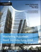
The workflow within a traditional design team is more complex than you might assume. If you were to graph the dependencies and coordination between these parties (Figure 6.1), you would see a web of primary relationships (architect to/from structure, architect to MEP) and secondary relationships (structure to/from mechanical and piping).
Figure 6.1 The relationships of interdisciplinary coordination
In addition, these relationships can be further parsed into physical and logical relationships. If we use mechanical and electrical as an example, you can see that a physical relationship means making sure a light fixture is not hitting the bottom of a duct, whereas a logical relationship means making sure the electrical design properly accounts for the load of the heating coil in a variable air volume (VAV) box (being designed by the mechanical engineer).
It is the complexity of these possible workflow scenarios that makes this process prone to errors, and illustrates the importance of proper coordination between the different disciplines of a design team. So, what are the tools that can be used for collaboration between Revit products? Three distinct tools are typically used in a collaboration scenario:
www.architecture-tech.com/2009/11/indiana-university-requires-bim.html
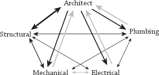
Given the range of available Revit tools for collaboration, they are not necessarily applicable to all interdisciplinary relationships. As shown in Figure 6.2, only the most appropriate tools should be applied to each collaborative situation. Note that these situations are merely suggestions based on the experience of the authors. The needs for your collaborative workflows may vary.
Figure 6.2 Suggestions for collaboration tools to be used between disciplines
Linked Models
The first rule governing all Revit-to-Revit coordination situations is that all linked project files must be generated with the same Revit platform version. For example, the architecture model must be generated with Revit® Architecture 2014, the structure model must be generated with Revit® Structure 2014, and the MEP model must be generated with Revit® MEP 2014. In a worksharing environment, it is also important to ensure that the computers of all team members working on a project have the same Revit build installed (Figure 6.3). As discussed earlier in this chapter, a BIM execution plan should include an agreement on all modeling and coordination software to be used on a project, including the version of each listed program.
Figure 6.3 Linked files must use the same platform version, and all worksharing team members should use the same build.

You can find the build information for your Revit product by clicking the Help drop-down button and selecting About Autodesk Revit 2014. The build appears at the upper right of the About Autodesk Revit 2014 dialog box.
Shared Positioning
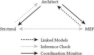
In the collaborative process of sharing information via linked models, the coordinated positioning of each model is of paramount importance. To ensure accuracy, every project’s BIM execution plan must include agreement on a common coordinate system and origin. This section will help you develop a fundamental understanding of the coordinate systems within Revit so you can configure and manage them in your projects.
We will begin our description with a simple statement: There are two coordinate systems in a Revit project: Project Internal and shared. Each system has essential features and limitations.
Figure 6.4 Diagram of the relationship between Project Internal origins and shared coordinates in linked models
Acquiring or Publishing Coordinates
When you attempt to synchronize shared coordinates between linked projects, there are two tools to achieve this: Acquire Coordinates and Publish Coordinates. A simple way to understand the difference between these tools is to think of them in terms of pulling versus pushing:
- Acquire = pull
- Publish = push
It is important to understand the situations in which you would pull or push coordinates between linked files. A typical workflow for establishing a synchronized, shared coordinate system on a single building project would be as follows:
For a campus-style project in which you might be creating multiple instances of a linked building model, you would most likely use Publish Coordinates to push information from a site model into the linked building model. Here’s how that would work in a hypothetical scenario:
Figure 6.6 The Project Base Point and Survey Point settings are found under Site in Visibility/Graphic Overrides.
Using Project Base Point and Survey Point
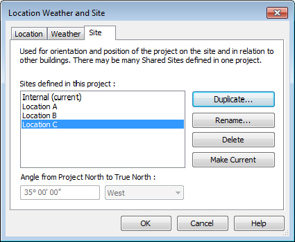
Revit provides two graphic objects to identify the Project Base Point and the Survey Point. In the default templates, these points are visible in the floor plan named Site; however, they can also be displayed in any other plan view by opening the Visibility/Graphic Overrides dialog box, selecting the Model Categories tab, and expanding the Site category, as shown in Figure 6.6. You can also use the Reveal Hidden Elements command in the view control bar to temporarily display these points.
Figure 6.5 Creating multiple locations for a single linked model

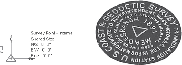
Figure 6.7 The Survey Point can be considered similar to a real-world geodetic survey marker.
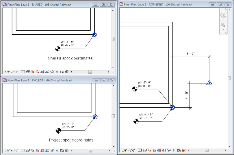
To further expand your understanding of these points and what happens when they are modified, we have created a sample file for your reference. Open the file c06-Shared-Points.rvt from this book’s companion web page (www.sybex.com/go/masteringrevit2014). In this file you will find three copies of the Level 1 floor plan. One view is configured to display the project coordinates, another view displays the shared coordinates, and the third view displays a combination of the two. There are also two types of spot coordinates: one indicating project coordinates in which the values are prefixed with the letter p and the other indicating shared coordinates with the prefix of s. You can open these three floor plans and tile the windows (click the View tab, select the Window panel, and choose Tile, or type the keyboard shortcut WT) to get a better sense of how these points affect one another (Figure 6.8).
Figure 6.8 Using tiled windows helps you examine the effect of project and shared coordinates.
In this sample file, you can explore the effects of moving the Project Base Point and Survey Point on your model’s coordinates. When selected, the Project Base Point and Survey Point have paperclip icons that determine the behavior of the points when you move them. Clicking the paperclip icon changes the state from clipped to unclipped and back to clipped.
The following is a list of the possible point modifications and explanations of how they affect the project. Note that in most cases you shouldn’t have to move the Survey Point or Project Base Point if you are using a linked Civil 2D or 3D file and acquiring the coordinates from the linked file.
Project Base Point: Clipped
- Move the PBP.
- PBP values change relative to the Survey Point.
- Project-based spot coordinates don’t change.
- Model elements “move” relative to shared coordinates.
Moving a clipped PBP is the same as using Relocate Project. That is, the model elements maintain their relationship to the PBP, but the relationship of the PBP to the Survey Point is changed.
Project Base Point: Unclipped
- Move the PBP.
- PBP values change relative to the Survey Point.
- Project-based spot coordinates change.
- Model elements don’t move.
Unclipping the PBP essentially detaches it from the internal project origin. Moving the unclipped PBP is only used to affect the values reported in spot coordinates set to the project origin base. It does not have any effect on exported files.
Survey Point: Clipped
- Move the SP.
- SP values don’t change.
- Shared spot coordinates change.
- Model elements don’t move.
The clipped Survey Point represents the origin of the shared coordinate system. Moving it is the equivalent of setting a new origin point. Use caution if you must move the shared coordinates origin if linked models already exist in which the shared coordinates have already been synchronized. In such a case, each linked model must be opened and manually reconciled with the model in which the origin has changed.
Survey Point: Unclipped
- Move the SP.
- SP values change.
- Shared spot coordinates don’t change.
- Model elements don’t move.
Moving an unclipped Survey Point essentially doesn’t do anything. It doesn’t affect spot coordinates and it doesn’t affect the origin of exported files.
Attachment vs. Overlay
Linked Revit models utilize what we will call a portability setting that is similar to the way Xrefs are handled in AutoCAD. Although this setting is not exposed when you initially link a Revit model, you can modify the setting by switching to the Insert tab and selecting Manage Links. Change the setting in the Reference Type column as desired (Figure 6.9).
Figure 6.9 Determining the reference type of linked Revit models
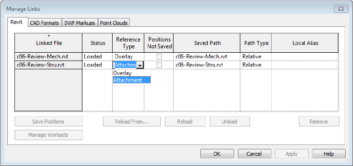
Figure 6.10 Notification of nested models using the Overlay setting

Links with Worksharing
If you are utilizing linked Revit models where one or more of the project files have worksharing enabled, there are a few guidelines to follow as well as some tangible benefits such as linked visibility control between worksets. Be sure to read more about worksharing in Chapter 5, “Understanding Worksharing,” before continuing with this section.
When you are linking worksharing-enabled files from consultants, you will first need to decide if you need to maintain the worksets in the linked files. Even though you may not have direct access to your consultants’ servers, the software will attempt to reconcile the location of each project model’s central file location. We recommend handling each received project file using one of the following options:
- Open the project using the Detach From Central option, choose Preserve Worksets, and then save the project as a new central file on your server. Refer to Chapter 5 for specific instructions on this process.
- Open the project using the Detach From Central option, choose Discard Worksets, and then save the file.
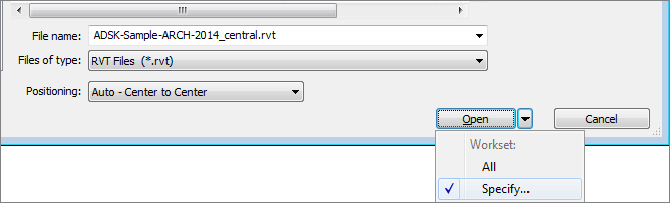
If your team decides to disable worksets in linked files received from consultants, you will avoid any problems related to the central file not being found; however, you will not be able to extend workset visibility settings into the linked files or use worksets to selectively load content from the linked model into your host project. If you preserve worksets, you can continue to use worksets in the linked model to your advantage. For example, when you first link a worksharing-enabled model into your project, you can use the Specify option associated with the Open button in the Import/Link RVT dialog box, as shown in Figure 6.11.
Figure 6.11 Use the Specify option to close worksets when linking.
At any time throughout the development of the project, you can adjust the loaded worksets from linked files very easily. From the Manage tab or the Insert tab in the ribbon, click the Manage Links button. In the Manage Links dialog box, select one of the linked RVT files, and if it is a worksharing-enabled file, the Manage Worksets button can be clicked (Figure 6.12) to open the Worksets dialog box.
Figure 6.12 Access worksets of linked files from Manage Links.

In addition to the workset-loading control, you can apply visibility settings automatically to linked models—as long as the worksets in any linked files are named exactly as they are in the host file. For example, if you linked a model that had the default workset named Shared Levels and Grids, and your host model also had that same workset, you can hide the workset in both the host and linked model in one step. Open the Visibility/Graphic Overrides dialog box, select the Worksets tab, and then set Shared Levels and Grids to Hide. You will see that any datum objects assigned to that workset—in either the host or linked model—are hidden. You do not need to perform a separate visibility override to the linked file.
While the automated visibility linking of worksets can be beneficial, it can also be problematic when you need to coordinate content between the host and linked models. In the same scenario described previously, what if you wanted the Shared Levels and Grids workset to be visible in the host model but hidden in the linked model? This is common when you are coordinating datum objects between architectural and engineering models. The grids and levels from a linked model should be visible for use with the Coordination Monitor tools described in this chapter, but then the linked references might need to be hidden. In this case, you might choose to access the Manage Worksets button discussed earlier and close the Shared Levels and Grids workset in the linked file. You could also adjust the linked view; however, this would require you to adjust every view in which the linked model appears. We discuss linked views in greater detail in Chapter 17, “Documenting Your Design.”
Using Worksets to Organize Linked Models
As we discussed in Chapter 5, we recommend that you create and reserve a workset for each linked Revit model, such as Link-RVT-Structure or Link-RVT-HVAC. This simple step will allow your team members to choose whether they would like any, all, or none of the linked models to be loaded when working on a host model. To enable this functionality, use the Specify setting in the drop-down options next to the Open button.
When the Worksets dialog box appears, select the worksets reserved for the linked models and set their Open/Closed status as you desire. The benefit of using worksets to manage linked Revit models is the flexibility it offers a project team. When a team member closes a workset containing a linked model, the linked model is unloaded only for that person—it does not unload for the entire team.
Workset Properties for Linked Models
Additional flexibility can be leveraged with the Workset parameter in both the instance and type properties of a linked model. In a large and complex project that consists of multiple wings where some of the wings are identical, each wing may consist of multiple linked models: architecture, structure, and MEP. Figure 6.13 shows a simplified representation of such a design where Wings A, D, and E are identical to one another, as are Wings B, C, and F.
Figure 6.13 Schematic representation of a complex project assembled with multiple linked models
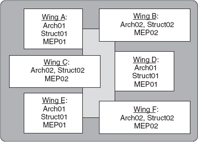
In Figure 6.13, there are two Revit models that represent wing design 01 and 02 for each discipline (Arch01, Arch02, and so on). Note that there are three instances of each linked model. For each instance of a linked model, you can specify the Workset parameter so that the workset instance property represents the wing, and the type property reflects either the entire discipline or one of the discipline models, as in this example:
- Instance workset: Wing A
- Type workset: Link-Architecture01 or simply Link-Architecture
Using this example, you can choose to open the Wing A workset, which would load all the discipline models, but only for Wing A, or you could choose to open the Link-Architecture workset, which would load only the architectural models but for all the wings. Note that you can modify the workset-type properties only after placing a linked model in your project. Access this setting by selecting an instance of a linked model and opening the Properties palette, and then click Edit Type. Although this functionality can offer a variety of benefits to your project team, it should be used with care and proper planning because it can adversely affect model visibility if you are using worksets for visibility manipulation.
Worksharing-enabled linked models also afford you the flexibility to adjust the visibility of project elements for the entire project, without relying on individual settings per view or maintenance of view templates. For example, grids and levels are not usually displayed from linked models because their extents are not editable in the host model and the graphics may not match those in the host model. Without worksets, the owner of the host model would have to establish visibility settings for the linked model within all views and hopefully manage those settings in view templates. Assuming the owner of the linked model maintains the levels and grids on an agreed-upon workset such as Shared Levels and Grids, you will be able to close that workset in one place, thus affecting the entire host project. To modify the workset options for linked Revit models, follow these steps:
Benefits and Limitations of Linked Models
To summarize using linked Revit models, let’s review some of the benefits and limitations. You should carefully consider these aspects not only when preparing for interdisciplinary coordination, but also when managing large complex projects with linked files.
The following list highlights some of the benefits:
The following list highlights some of the limitations:
Exercises: Using Linked Models
![]() Before beginning the exercises in this chapter, download the related files from this book’s web page. The project files in each section’s exercise should be saved because the lessons will build on the data. In this exercise, you will do the following:
Before beginning the exercises in this chapter, download the related files from this book’s web page. The project files in each section’s exercise should be saved because the lessons will build on the data. In this exercise, you will do the following:
- Link the architectural model to a structural project.
- Establish shared coordinates.
Note that the structural model is essentially a blank project with a few element types specifically built for this chapter’s lessons. Let’s get started working with shared coordinates:
Modifying Element Visibility in Linked Files
Once you have linked one or more Revit files into your source project file, you may want to adjust the visibility of elements within the linked files. By default, the display settings in the Visibility/Graphic Overrides dialog box are set to By Host View for linked files, which means model objects in the linked files will adopt the same appearance as the host file. In the following exercise, we’ll show you how to customize these settings to turn the furniture off in the linked file and then display the room tags:
Figure 6.14 Enable all custom display settings for a linked RVT file.
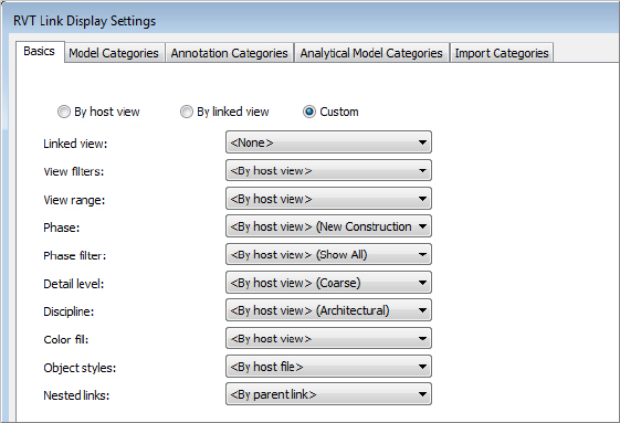
Figure 6.15 Enable custom display settings for model categories of a linked RVT file.

You should observe that all the furniture and casework from the linked architecture file are no longer visible in the Level 1 floor plan. In a standard architecture-to-structure collaboration scenario, the structural engineer is likely to have a view template in which typical architectural elements are already hidden. In such a case, the default By Host View settings would be sufficient. The previous exercise illustrates a scenario where additional visual control is required.
Using Linked Views
Whereas the previous exercise focused on the display of model elements, a slightly different approach is required to utilize annotation elements from a linked file. In the following exercise, we will show you how to display the room tags from the linked architectural model. Note that many other tags can be applied to linked model elements. Here are the steps:
After completing these steps, you should see the room tags from the linked architectural file in the host file. Remember that you can tag other model elements in linked files. Try using the Tag By Category tool to place some door tags on the linked architectural model.
Coordination Tools
Once you have established the configuration of linked Revit models for your project, the next step is to create intelligently bound references between specific elements within the models. In the past, CAD users might have referenced files containing grid lines or level lines to establish a level of coordination between one user’s data and another’s. Note that these elements in CAD are merely lines—not datum objects as they are in a Revit model. If these referenced elements were modified in a CAD setting, the graphic appearance of the referenced lines would update, but there would be no additional automated response to the geometry. It would be the responsibility of the recipient to update any referring geometry in their host files.
The coordination tools in Revit—Copy/Monitor and Coordination Review—allow a project team to ensure a high degree of quality control while achieving it at an increased level of productivity. These tools can function on datum (levels and grids) as well as model elements such as columns, walls, floors, and fixtures. The Copy/Monitor command is used first to establish the intelligent bonds between linked elements and host elements, whereas the Coordination Review command automatically monitors differences between host and linked elements that were previously bound with the Copy/Monitor command.
Although these tools are indeed powerful and have no similarities to CAD workflows of the past, it is important to employ proper planning and coordination with your design team. The familiar adage of “quality over quantity” holds true for the implementation of coordination tools. It may not be necessary to create monitored copies of all structural elements within the architectural model. How would these affect project-wide quantity takeoffs for the sake of minor improvements in graphic quality?
We reiterate the necessity of developing a BIM execution plan to determine important aspects of the collaboration process. When using specific coordination tools such as those in Revit, teams might plan on issues such as these:
- Who is the “owner” of grids and levels?
- Who is the “owner” of floor slabs?
- Are structural walls copied, monitored, or just linked?
- How often are models exchanged?
- How are coordination conflicts resolved?
A seemingly powerful BIM tool will not replace the need for professional supervision and the standard of care implicit to respective disciplines in the building industry. Thus, there is no substitution for the most important part of effective collaboration: communication. Without open and honest communication, the coordination tools will discover conflicts, but the results may be ignored, dismissed, or overwritten, to the detriment of the team’s progress.
Copy/Monitor
![]() The Copy/Monitor command allows you to create copies of linked elements for better graphic control of the elements while maintaining an intelligent bond to the linked elements. If the linked element changes in a subsequent iteration of the project file, the changes are detected in the Coordination Review tool, which we will discuss next.
The Copy/Monitor command allows you to create copies of linked elements for better graphic control of the elements while maintaining an intelligent bond to the linked elements. If the linked element changes in a subsequent iteration of the project file, the changes are detected in the Coordination Review tool, which we will discuss next.
With the structural model saved from the “Using Linked Models” exercises, switch to the Collaborate tab and select Copy/Monitor ![]() Select Link. Pick the linked architectural model, and the ribbon will change to Copy/Monitor mode. Click the Options icon to open the dialog box shown in Figure 6.16.
Select Link. Pick the linked architectural model, and the ribbon will change to Copy/Monitor mode. Click the Options icon to open the dialog box shown in Figure 6.16.
Figure 6.16 Element tabs available for Copy/Monitor in Revit Architecture
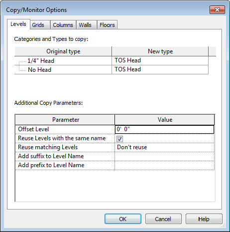
As shown in Figure 6.16, the Copy/Monitor Options dialog box in Revit is divided into five tabs representing the elements available to be copied and/or monitored. For each element tab, there is a list called Categories And Types To Copy. As shown in Figure 6.17, the Floors tab lists the available floor types in the linked model in the left column and host model floor types in the right column. Notice that any of the linked types can be specified with the option Don’t Copy This Type. This feature can be used for quality control if your project’s BIM execution plan states that certain elements are not to be copied. For example, if walls are not to be copied, switch to the Walls tab and set all linked wall types to Don’t Copy This Type. You can also use the option Copy Original Type if the element type exists in the linked file but not in the host file. After one or more of these elements are selected using Copy/Monitor, the type mapping will be synchronized.
Figure 6.17 The Copy/Monitor Options dialog box allows customization for intelligent collaboration.

At the bottom of the Copy/Monitor Options dialog box, you will find a section called Additional Copy Parameters for each element tab (refer to Figure 6.16). Note that the additional parameters are different for each element category. For example, when levels are copied and monitored, an offset and naming prefix can be applied to accommodate the difference between the finish floor level in a linked architectural model and the top of steel level in the host structural model.
Let’s take a closer look at each of the element category options available for the Copy/Monitor tool:
Exercise: Using Copy/Monitor
Continue with the structural model saved in the previous exercise in this chapter. In this exercise, you will do the following:
- Use Copy/Monitor to establish new levels and grids.
- Use Copy/Monitor to create floors.
- Link the new structural model back to the architectural model.
- Use the Monitor option for grids in the architectural model.
These steps will establish the intelligent bonds between elements in the host file with the related elements in the linked model. With the structural model open, activate the South elevation view. Then follow these steps:
- 1/4″ (8 mm) Head = TOS Head
- Offset Level: -0′-6″ (150 mm)
- Add the prefix to Level Name: T.O.S.
- 1/4″ (6.5 mm) Bubble = 1/4″ (6.5 mm) Square
- Arch Slab 6″ (150 mm) = LW Concrete on Metal Deck
- Set all other entries under Original Types to Do Not Copy This Type.
- Copy Openings/Inserts: Yes (checked)
If you now select any of the grids or levels in the host file, you will see a monitor icon near the center of the element. This icon indicates that the intelligent bond has been created between the host and the linked element and will evaluate any modifications in the linked file whenever the file is reloaded.
Save and close the structural model and then open the architectural model. Using the procedures you have learned in this chapter, link the structural file into the architectural model. Placement should be done in the Level 1 floor plan using Auto – By Shared Coordinates positioning.
Use the Copy/Monitor tools in Monitor mode to establish the relationships of the grids between host and linked models. Doing so will ensure that changes to grids in either model will be coordinated.
Coordination Review
![]() After intelligent bonds have been established between elements in linked models, it is the purpose of the Coordination Review tool to support the workflow when datum or model elements are modified. This tool was designed to allow the recipient of linked data to control how and when elements in host models are modified based on changes in the linked models.
After intelligent bonds have been established between elements in linked models, it is the purpose of the Coordination Review tool to support the workflow when datum or model elements are modified. This tool was designed to allow the recipient of linked data to control how and when elements in host models are modified based on changes in the linked models.
When a linked model is reloaded—which will happen automatically when the host model is opened or when you manually reload the linked model in the Manage Links dialog box—monitored elements will check for any inconsistencies. If any are found, you will see a warning message that a linked instance needs a coordination review.

The Coordination Review warning is triggered when any of the following scenarios occur:
- A monitored element in the linked model is changed, moved, or deleted.
- A monitored element in the host model is changed, moved, or deleted.
- Both the original monitored element and the copied element are changed, moved, or deleted.
- A hosted element (door, window, opening) is added, moved, changed, or deleted in a monitored wall or floor.
- The copied element in the host file is deleted.
To perform a coordination review, switch to the Collaborate tab and select Coordination Review ![]() Select Link. After picking one of the linked models, you will see the Coordination Review dialog box, which lists any inconsistencies in monitored elements (Figure 6.18).
Select Link. After picking one of the linked models, you will see the Coordination Review dialog box, which lists any inconsistencies in monitored elements (Figure 6.18).
Figure 6.18 The Coordination Review dialog box lists inconsistencies in monitored elements.
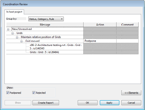
For each of the changes detected in the Coordination Review dialog box, one of the following actions can be applied. Note that actions resulting in changes to elements will be applied only to the host model; they do not modify elements in a linked model. Also note that not all options are available for all monitored elements.
As you can see, Coordination Review can be a powerful tool to support the collaboration process. Remember that such a tool may not be appropriate for all elements at all times. For example, instead of copying and monitoring columns and grids, it may be sufficient to copy and monitor only grids because the columns placed in your host model will move with the grids anyway.
Exercise: Using Coordination Review
In this exercise, you will utilize two files that have already been linked together with monitored elements between both files. You can download the files c06-Review-Arch.rvt (architectural model) and c06-Review-Stru.rvt (structural model) from this book’s web page. In this exercise, you will do the following:
- Modify elements in the architectural model.
- Use Coordination Review to address these changes in the structural model.
Remember that you can’t have a host model and a linked model open in the same Revit session. To make this lesson easier, you can launch a second Revit session. Open c06-Review-Arch.rvt or c06-Review-Arch-Metric.rvt in one session and c06-Review-Stru.rvt or c06-Review-Stru-Metric.rvt in the other. Then follow these steps:
- Move grid line F to the north by 2′-0″ (600 mm).
- Rename grid 6 to 8.
In the previous exercise, you might have noticed the appearance of a monitored floor sketch. Why did a floor sketch change if you only moved a grid and renamed another? The answer lies in constraints and relationships. The exterior wall in the architectural model was constrained to be 2′-0″ (600 mm) offset from grid line F. When it was moved, the exterior wall was moved to maintain the offset. The sketches of the model’s floor slabs were created using the Pick Walls tools, creating an intelligent relationship to the wall. The modified grid affected the wall, which modified the floor, and the Coordination Monitor tools ensured that all changes were detected and presented to you for action.
Interference Checking
In addition to asset management, digital fabrication, and cost estimation, 3D coordination is one of the most important uses of building information modeling. It has enormous potential to reduce the costs of construction through the computerized resolution of clashing building elements as well as exposing opportunities for alternate trade scheduling or prefabrication. The key component to achieving 3D coordination is interference checking, also known as clash detection.
- Mechanical Ductwork and Piping vs. Ceilings
- Mechanical Ductwork and Piping vs. Rated Walls (for coordination of dampers and other mechanical equipment needs)
- Mechanical Ductwork and Piping vs. Structure (columns, beams, framing, etc.)
- All Equipment and Their Applicable Clearances vs. Walls
- All Equipment and Their Applicable Clearances vs. Structure
- Mechanical Equipment and Fixtures vs. Electrical Equipment and Fixtures
- Mechanical Ductwork and Piping vs. Plumbing Piping
- Casework vs. Electrical Fixtures and Devices
- Furnishings vs. Electrical Fixtures and Devices
- Structure vs. Specialty Equipment
- Structure vs. Electrical Equipment, Fixtures, and Devices
- Ductwork and Piping vs. Electrical Equipment, Fixtures, and Devices
- Ductwork vs. Floors
- Casework vs. Walls
- Plumbing Piping vs. Electrical Equipment, Fixtures, and Devices
- Plumbing Piping vs. Mechanical Equipment, Fixtures, and Devices
- ADA Clear Space Requirements vs. Doors, Fixtures, Walls, Structure
Tools for Interference Checking
The Interference Check tool is a basic tool supporting 3D coordination. You can use it within a single project model or between linked models. You can also select elements prior to running the tool in order to detect clashes within a limited set of geometry instead of the entire project.
For more powerful clash detection capabilities, Autodesk offers Navisworks® Manage (www.autodesk.com/navisworks), which is a multiformat model-reviewing tool with various modules supporting phasing simulation, visualization, and clash detection. Figure 6.19 shows an example of a model in Navisworks Manage comprising Revit, Tekla Structures, and AutoCAD MEP components. Some of the benefits of using Navisworks for interference checking over Revit include automated views of each clash, grouping of related clashes, enhanced reporting, clash-resolution tracking, and markup capabilities. Revit models can be opened directly in Navisworks or exported directly to Navisworks format from the Application menu.
Figure 6.19 3D coordination model in Navisworks Manage

Exercise: Running an Interference Check
![]() Let’s take a look at the Revit interference-checking process. For this exercise, you will need to download three sample files to your computer or network: c06-Interference-Arch.rvt, c06-Interference-Mech.rvt, and c06-Interference-Stru.rvt. You can download these files from this book’s web page. The sample files are already linked into each other using relative paths, so be sure to place all three files in the same folder. Then follow these steps:
Let’s take a look at the Revit interference-checking process. For this exercise, you will need to download three sample files to your computer or network: c06-Interference-Arch.rvt, c06-Interference-Mech.rvt, and c06-Interference-Stru.rvt. You can download these files from this book’s web page. The sample files are already linked into each other using relative paths, so be sure to place all three files in the same folder. Then follow these steps:
Figure 6.20 Select categories to be included in an interference check.
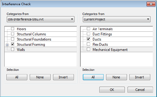
Figure 6.21 Results of an interference check are displayed in the Interference Report window.

Note that you can navigate in the 3D view using any method (mouse, ViewCube®, or SteeringWheels®) while keeping the interference report open. This facilitates resolution of the clashing items. The results of the interference check can also be exported to an HTML format report. Click the Export button and specify a location for the report. You can then share this report with other members of your design team for remedial actions on linked models.