
Modeling is the process of creating 3D objects, whether for animation or other purposes. Simple objects call for simple models, and complicated objects call for a complex of simple models. One of the toughest decisions is how to represent an object in 3D. Like a sculptor, you analyze the object and deconstruct its design to learn how to create it.
Maya uses three types of modeling: polygons, NURBS, and subdivision surfaces. All three require a process that begins with deciding how best to achieve your design, though it is common to mix modeling methods in a scene.
To help you decide where to begin, this chapter starts with an overview of modeling, briefly describing the three methods and how they differ. You'll also learn about Maya's primitives, which are available with all three modeling methods. The second part of the chapter takes a detailed look at modeling with polygons. (The next two chapters cover the process of modeling with polygons and subdivision surfaces and how to bring them together in one model.)
Topics in this chapter include:
Planning Your Model
Polygon Basics
Poly Editing Tools
Putting the Tools to Use: Making a Simple Hand
Creating Areas of Detail on a Poly Mesh
Modeling Complex Objects: The Classic Steam Locomotive
Suggestions for Modeling Polygons
The first step in making any object is to understand how it's constructed. The best training for a CG modeler is to visualize the elements that make up an object. Dissecting the components of an object into primitive shapes will help you translate and re-create it in 3D terms. You create the elements in Maya and then join them together to form the desired object.
Gather as much information as you can about the object you want to model. Take pictures from many angles, get sizes and dimensions, and even write down a description of the object. Try to re-create it in a different medium, such as a charcoal sketch or a simple clay or balsa-wood model. Why go through these steps before you start the model in Maya? The more perspectives from which you see your subject, the better you will understand and be able to interpret your model.
Maya has a rich toolset for creating models, so it's important to choose the methodology that best matches the modeling task at hand. Be prepared with sketches, pictures, and whatever information you can gather before you sit down to realize your CG model.
How detailed should your model be? This is a crucial question, because a model that's too complex, or a scene that has too much detail, wastes precious computing time and power, which will greatly increase render times.
Begin by deciding the purpose for your model. Then determine the level of detail at which it will be seen in your CG scene. For example, consider the two scenes in Figure 4.1. If you need to create a park bench that is shown in a far shot (left), it will be a waste of time and effort to model all the details such as the grooves in the armrest. If, however, your park bench is shown in a close-up (right), you'll need those details. It is important to plan your model in accordance with the level of detail it requires.
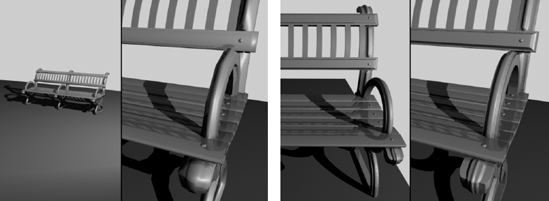
Figure 4.1. The level of detail you need to include in a model depends on how it will be seen in the animation.
If you aren't certain how much detail you will need, it is better to create a higher level of detail rather than skimping. You can easily pare down the detail if it becomes unnecessary in the scene.
Keep in mind that you can add detail to your model in the texturing phase of production. You would be amazed at the richness of detail a model can achieve with simple geometry and well-painted texture maps. (Chapter 7, "Maya Shading and Texturing," covers texturing.) It is also important to keep in mind that in the rendering phase, you can run into memory shortcomings if you have too many scene models or they are overly detailed. Finding the right balance is tough, but it will come with time and experience.
As the geometry detail increases in a model, the performance demands on your PC can skyrocket. If you are working with a slower machine or a with low-end graphics card, your models will have to be especially well thought out in terms of their level of detail. Equipped with this decision and hopefully a number of photos, web pictures, and sketches, you will find your modeling experience more productive.
A fundamental decision you'll make in planning is choosing a modeling method. Maya can define a model in three ways: polygons, NURBS, and subdivision surfaces. (Polygons are the subject of this chapter. NURBS and subdivision surfaces are the subjects of Chapter 5, "Modeling with NURBS, Subdivisions, and Deformers.") Although NURBS modeling is what Maya modeling is renowned for, polygons are the simplest to describe.
Polygons are made up of faces. A single polygon face is a flat surface made when three or more points called vertices are connected. The position of each vertex defines the shape and size of the face, usually a triangle. The line that connects one vertex to another is called an edge. Some polygonal faces have four vertices instead of three, creating a square face instead of a triangular one.

Polygonal faces are attached along their polygonal edges to make up a more complex surface that constitutes your model (as shown with the polygonal sphere in Figure 4.2). A camping tent is a perfect example. The intersections of the poles are the faces' vertices. The poles are the edges of the faces, and the cloth draped over the tent's frame is the resultant surface.
Polygon models are the simplest for a computer to render. They are used for gaming applications, which need to render the models as the game is running. Gaming artists create models with a small number of polygons, called low-count poly models, which a PC or game console can render in real time. Higher-resolution polygon models are frequently used in television and film work. In fact, a number of science fiction TV shows use polygonal models almost exclusively for their special effects. Because even complex polygon models can be made of a single surface, they are useful for character animation work as well. Models in character animation bend and warp a good deal, so having a single surface that will not separate at the seams can be advantageous. You'll get hands-on practice with polygon modeling later in this chapter.
NURBS is an acronym for Non-Uniform Rational B-Spline. NURBS modeling is based on mathematics that is more complicated than the mathematics for polygons. Because NURBS modeling requires more processing, this method is typically used for applications in which the rendering is done in advance, such as animation for film or television. NURBS modeling excels at creating curved shapes and lines, so it is most often used for organic forms such as animals and people, as well as highly detailed cars and the like. These organic shapes are typically created with a quilt of NURBS surfaces, called patches. Patch modeling can be powerful in creating complex shapes such as characters.
NURBS geometry is based on Bézier curves, a math concept originally developed by the French engineer Pierre Bézier. Bézier curves are drawn between control vertices (CVs) based on equations using cubic polynomials.
In essence, Bézier curves are created with a starting and an ending CV and at least two CVs in between that provide the curvature. As each CV is laid down, the curve or spline tries to go from the previous CV to the next one in the smoothest possible manner.
As shown in Figure 4.3, CVs control the curvature. The hulls connect the CVs and are useful for selecting multiple rows of CVs at a time. The starting CV appears in Maya as a closed box. The second CV, which defines the curve's direction, is an open box, so you can easily see the direction in which a curve has been created. The curve ends, of course, on the end-point CV. The start and end CVs are the only CVs that are always actually on the curve.
Whereas CVs control the curvature of a Bézier spline, NURBS surfaces are defined by curves called isoparms, which are created with CVs. The surface is created between these isoparms to form spans that follow the surface curvature defined by the isoparms, as in Figure 4.4. The more spans, the greater the detail and control over the surface; but this added detail makes greater demands on the computer, especially during rendering.


Unlike a polygonal model, a NURBS surface deformation is based on the interpolation of curves, which must interpret a deformation of polygons as a collection of faces created from straight edges. For that reason, it is easier to get a smooth deformation on a NURBS surface with few CVs. To get the same smooth look on a polygon would take much more surface detail.
As you can see in Figure 4.5, NURBS modeling yields a smoother deformation, whereas polygons can become jagged at the edges.
If your model requires smooth curves and organic shapes, use NURBS. When in doubt, however, it is better to begin modeling with NURBS. You can convert NURBS to polygons at any time, but converting back to NURBS can be tricky.

Figure 4.5. A NURBS cylinder (left) and a polygonal cylinder (right) bent into a C shape. The NURBS cylinder remains smooth, and the polygon cylinder shows its edges. A NURBS object retains its smoothness more easily, although it is possible to create a smooth polygon bend with increased surface faces.
Note
NURBS modeling is losing its popularity overall to newer and better polygonal modeling and subdivision techniques. It is, however, an excellent way to create smooth surfaces and difficult organic shapes, even though the resulting geometry is very frequently converted to polygons for rigging, texturing, and rendering.
You'll get important hands-on practice with NURBS surface modeling with NURBS patching in the next chapter.
Try This Open a new scene (choose File → New Scene). In the new scene, you'll create a few curves on the ground plane grid in the Perspective (persp) panel. Maximize the perspective view by moving your cursor to it and pressing the spacebar. Choose Create → CV Curve Tool. Your cursor will turn into a cross. Lay down a series of points to define a curved line on the grid. Notice how the actual Bézier curve is created between the points (CVs) as they are laid down.
Subdivision surfaces incorporate the best of polygons and NURBS modeling to give you the ease of polygon creation plus the smoothness and organic forms of NURBS geometry.
Subdivision surfaces usually start as polygonal surfaces. You then use NURBS math to smooth the rough polygon surfaces by subdividing them according to how the model needs to look. For example, you can easily turn a poly cube into a sphere by using subdivisions to subdivide the faces into smaller and smaller faces that are rearranged to form the sphere along smooth curves used to define this new surface.
With this technique, you can create simple poly models quickly and then overlay them with levels of detail to define the new smooth surface. You can go back to the original poly model at any time to make large-scale changes quickly and efficiently.
Furthermore, with subdivision surfaces you have the added advantage that your surface will not tend to crease or tear at the seams as NURBS models made of patches of surfaces are prone to do. This leads to better models with which to animate organics.
The disadvantage of subdivision surfaces is that they require even more computation than NURBS, and keeping models in subdivisions will cost you a lot of memory. It's almost always the best practice to convert subdivisions (subDs) back to polygons. You will also get hands-on practice with subdivision surface modeling in the next chapter.
Maya provides highly effective tools for all three types of modeling, so you can make a model with any technique in as much detail as necessary. The choice depends on how you prefer to model.
Polygons are a welder's tool. Polygon modeling involves tearing and extruding from larger pieces and welding several surfaces together to form a desired whole. Orthogonal models (models with straight lines and sharp corners) are created more easily with polys.
A clay sculptor might prefer NURBS. Pushing and pulling CVs to create subtle curves on the surface is like working soft clay with your fingertips; you are nurturing something into shape with the fine art of pressure.
Subdivision surfaces combine the best of both worlds. An artist can begin with a rough shape, chisel it out coarsely, and then switch to finely detailed sculpting by adding levels of detail to the sculpture only when and where needed. Subdivision surface modeling excels at creating organic shapes out of single surfaces.
In the end, converting everything back to polygons is almost always preferable. Why? The available rendering applications all turn everything to polygons (a process called tessellation) when they render the scene. You can save yourself some memory and time and be the master of your own models by trying to go back to polygons as often as is reasonable.
Primitives are the simplest objects that you can generate in Maya (or indeed in any 3D application). Primitives are simple geometric shapes—polygons, subdivisions, or NURBS. Typically, they are used to sculpt models, as you saw with the Solar System project in Chapter 2, "Jumping in Headfirst, with Both Feet."
Because you can define the level of detail of the primitive's surface, primitives offer great sculpting versatility through vertex or CV manipulation. You can create polygonal primitives using practically any level of subdivisions to define the number of vertices and faces. NURBS primitives can be created with almost any number of sections and spans to define the number of isoparms and CVs.
Note
Spans are isoparms that run horizontally in a NURBS surface; sections are isoparms that run vertically in the object.
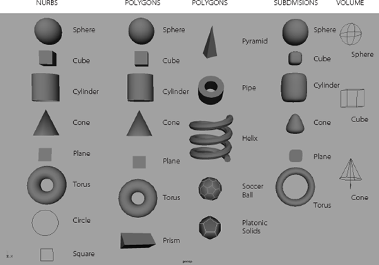
Starting with primitives, a modeler can create highly complex and detailed models. You may find it helpful to analyze your modeling subjects into forms and shapes that fit in with Maya primitives to get a better sense of how to begin a modeling assignment. Figure 4.6 shows all of Maya's primitives, NURBS, polygons, subdivisions, and volume primitives. Quite different from geometry primitives, volume primitives are used for lighting and atmosphere effects such as fog or haze and do not play a part in modeling.
In addition to using less bandwidth to render, polygon modeling is popular because its resulting models are usually one piece of geometry with many facets. You can, therefore, deform polygon models without fear of patches coming apart, as can happen with NURBS. Polygons, however, have a finite detail limitation and can look jagged up close or when scaled up. One solution to this problem in the Maya software is the Smooth tool. Many 3D applications support only this form of modeling, so it is a popular exchange method among platforms.
Polygons are inherently better for orthogonal models, mechanical objects, and the like. Character modeling with polygons, however, is quite powerful once you understand the tools to edit polygons. A popular method of polygonal modeling, sometimes called box modeling, involves creating a base object, such as a simple cube, and then pulling and pushing faces to draw out angles to create more faces. Whereas NURBS typically need the creation of curves to start, complex polygons are usually created from basic-shaped polygons such as primitives.
Another method for creating poly surfaces uses the same curves that NURBS surfaces use or even converts a completed NURBS surface model to polygons. A third method is to create poly surfaces directly with the Polygon tool, which allows you to outline the shape of each face. We'll take a look at these procedures in the next chapter.
The most notable difference between the options for a NURBS primitive and a poly primitive are the options for surface detail. With a NURBS surface, sections and spans define detail. With a poly surface, detail is defined by subdivisions, which are the number of rows and columns of poly faces that run up, down, and across. The more subdivisions, the smoother the surface will be.
Choosing Create → Polygon Primitives gives you access to the poly version of most of the NURBS primitives. Opening the option box for any of them gives you access to their creation options. To see an example, choose Create → Polygon Primitives → Sphere and open the option box.
To get started, first make sure that History is turned on or there will be no creation node; then click Create to make the poly sphere. Open the Attribute Editor and switch to its creation node, called polySphere1. In the creation node polySphere1, just as in the option box, you'll find the Subdivisions Axis and Subdivisions Height sliders, which you can use to change the surface detail retroactively.
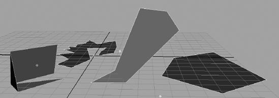
You use the Polygon tool (switch to the Polygons menu set, then choose Mesh → Create Polygon Tool) to create a single polygon face by laying down its vertices. When you select this tool, you can draw a polygon face in any shape by just clicking down the position of each point or vertex. Aside from creating a polygon primitive by choosing Create → Polygon Primitives, this is the simplest way to create a polygon shape. Figure 4.7 shows some simple and complex single faces you can create with the Polygon tool.
Once you have laid down all your vertices, press Enter to create the poly face and exit the tool. On complex shapes, you might want to create more than just the single face so that you can manipulate the shape. For example, you might want to fold it.

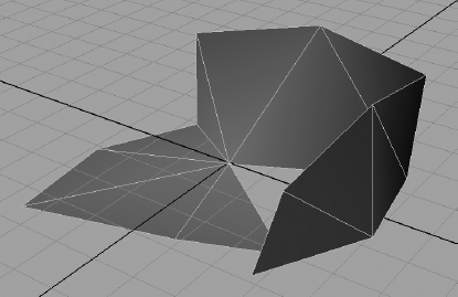
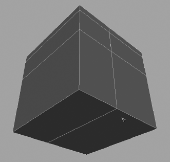
Try This The poly shown in Figure 4.8 was created with the Polygon tool and has only one face. Therefore, adjusting or deforming the surface is impossible. To fold this object, you need more faces and the edges between them. Make your own intricate poly shape with the Polygon tool by clicking vertices down in the different views to get vertices in all three axes.
With the surface selected, choose Mesh → Triangulate. The surface will have more faces and edges and be easier to edit, but it was still simple to create because you started with a single face. If you need a uniquely shaped poly, start with this tool, and then triangulate your surface into several faces as shown in Figure 4.9.
As you've learned, you can easily create complex models by adjusting existing, simpler poly objects with some of the poly editing tools that Maya provides. Here's a brief preview of what to expect in the world of poly editing. You should experiment with each tool on a primitive sphere as it is introduced, so saddle up to your Maya window and try each tool as you read along.
Later in this chapter, you'll deploy these new skills on two different poly models. In Chapter 6, "Building the Red Wagon," you will create a red wagon to be used throughout the rest of this book to texture, light, and render. For most of the work in this chapter, you will use the Polygons menu. Open the Edit Mesh menu and tear it off to place somewhere on your screen, so that you can get a good look at the tools and functions. You can access all the following tools from that menu.
The most commonly used poly editing tool has to do with extrusion. You can use Extrude to pull out a face or an edge of a polygon surface to create additions to that surface. The tool itself is accessed at Edit Mesh → Extrude. Maya will distinguish between edge or face Extrude based on whether you have selected edges or faces. Follow these steps:
Select a face or multiple faces of a polygon, and choose Edit Mesh → Extrude. The regular manipulator will change to a special manipulator, as shown in the left side image in Figure 4.10.
Grab the Z-axis move handle (the blue arrow), and drag it away from the sphere, as shown in the center of Figure 4.10.
Using the scale handles (the boxes) will scale the faces of the extrusion. The cyan circle will rotate the face. The image on the right in Figure 4.10 shows the faces extruded, rotated, and scaled.
Choosing the Extrude command again without deselecting the faces will let you extrude even more, keeping the original extrusion shape and building on top of that.
Selecting the edges of the poly surface instead of the faces and choosing Edit Mesh → Extrude will extrude flat surfaces from the edges selected. The special manipulator works the same way as Extrude does for poly faces.
Note
The face(s) you selected pull out from the sphere, and new faces are created on the sides of the extrusion(s). The Extrude tool is an exceptionally powerful tool in that it allows you to easily create additions to any poly surface in any direction. It is particularly useful for modeling characters and creatures. Later in this chapter, you'll use it to make a simple human hand.
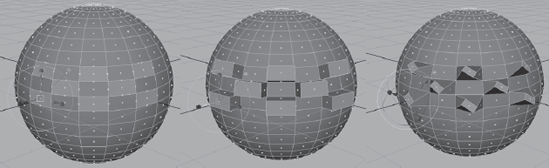
Figure 4.10. Extruding several faces at once on a sphere. The left shows the selected faces, the middle shows those faces extruded, and the right shows those faces extruded with a rotation and smaller scale.
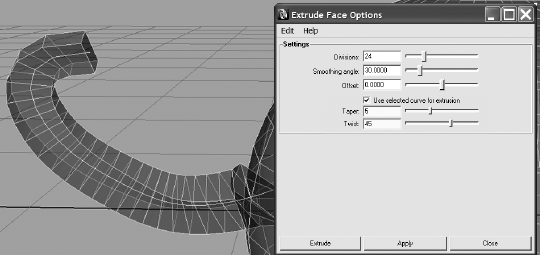
You can also use the direction and shape of a curve to extrude faces. Create a curve in the shape you want your extrusion to take, select the curve along with the face(s), and choose Extrude
This seems to be strange behavior, but the Twist and Taper values are taken into account in the extrusion. You can edit these values when you uncheck Use Selected Curve For Extrusion, or you can check it back on after you enter values for Twist and Taper. If your faces aren't extruding to the shape of the curve, increase the number of divisions.

Similar to extruding faces, Wedge Face pulls out a poly face, but it does so in an arc instead of a straight line. For this tool, you need to select a face and an edge of the selected face for the pivot point of the corner. Here's how to do this.
Select a face, Shift+select one of its edges, and choose Edit Mesh → Wedge Face
In the option box, you will notice some help for the tool under the Description heading. Under the Settings heading, you can select the degree of turn in the arc angle (90 degrees is the default) as well as the number of faces used to create the wedge (by moving the Divisions slider) as shown in Figure 4.12.
To access selection filters more easily, you can right-click an object to display a marking menu. Drag the cursor in the direction of the selection type you want, and release the mouse button. Then click or Shift+click your selection.
The Wedge Face tool is useful for items such as elbows, knees, archways, and tunnel curves.
Poke Face is great for creating detailed sections of a mesh (poly surface) and bumps or indentations. To use the Poke Face tool to add detail to a face, select a face, and then choose Edit Mesh → Poke Face.

A vertex is added to the middle of the face, and the Move manipulator appears on the screen as shown in Figure 4.13. This lets you move the point to where you need it on the face. You can add bumps and depressions to your surface as well as create regions of extra detail. By selectively adding detail, you can subdivide specific areas of a polygon for extra detailed work, leaving lower poly counts in less-detailed areas for an efficient model.
Using the Bevel tool to edit polygons is similar to using the NURBS version, but only if Bevel is used to round sharp corners. The Bevel tool requires that you select an edge or multiple edges and then use them to create multiple new faces to round that edge or corner.

Select an edge or edges and choose Edit Mesh → Bevel
The setting of the Roundness slider specifies the roundness of the corner. Setting the number too high will make the beveled edge stick out, as shown in Figure 4.15, although that can be a valid design choice. You can allow Maya to set the roundness automatically based on the size of the geometry being beveled. Check the Automatically Fit Bevel to Object check box to disable the Roundness slider. Move the Segments slider to set the number of new faces that are created on the bevel: the more segments, the smoother the bevel.
Use the Bevel tool to round polygonal edges. You can also use it to add extra surface detail, because Bevel creates more faces on the surface.

Starting with a simple polygonal cube, you will create a basic human hand.
Now either create a new project called Poly_Hand or copy the entire project from the CD and use that. Follow these steps:
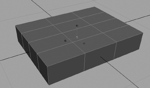
Begin by creating a polygonal cube. Open the Attribute Editor and, in the polyCube1 tab, set Subdivisions Width to 4, Subdivisions Height to 1, and Subdivisions Depth to 3. If you don't have that tab in the Attribute Editor, click Undo, turn History on, and re-create the cube.
Scale the cube to X = 1, Y = 0.25, and Z = 1.3, so that it looks as shown in Figure 4.16.
Enter Component mode (F8), and turn on the Faces filter

Select the front face that is in the corner closest to you by clicking its little blue handle box. You will extrude the face to make the first part of the index finger. Before you extrude, though, rotate the face a little bit out in the Y-axis, away from the rest of the hand, to angle the extrusion out toward where the thumb would be.
Choose Edit Mesh → Extrude, and use the Z-axis translate handle to pull out the face to a distance of 0.4 in the Local Translate Z attribute in the Channel box. This is the first segment of the index finger. Select the Extrude command for a new extrusion. Extrude the second segment of the finger out to 0.4 in Local Translate Z. Use Extrude again for the tip of the index finger, pulling that out to 0.3. Figure 4.17 shows the full index finger with the slight rotation away from the hand.
Save your work and compare it to the scene file
poly_hand_v1.mbin the Poly_Hand project on the CD.
Repeat steps 4 and 5 for the remaining three fingers. Remember, if you rotate the initial face of each finger a little bit away from the previous finger, the extrusions will have small gaps between them, as shown in Figure 4.18. Otherwise, the fingers will extrude right up against each other, like a glove with the fingers glued together.
Use Table 4.1 as a guide for the extrusion lengths for the different parts of each finger:
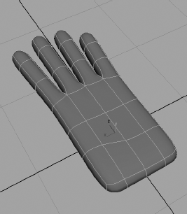
When you are done with the four fingers, select the hand and, in the Perspective panel, press 2 to give you a smooth preview of the hand. Way back in Chapter 3, we discussed levels of detail in the view panels. With a polygonal object, pressing the 1, 2, and 3 keys will preview the smoothness your model will likely have when it is smoothed (a polygonal modeling operation about to be discussed). When you press 2, your hand is previewed smoothed. It also shows the original shape of the hand as a wireframe cage as shown in Figure 4.19.
With the hand still selected, press 3 and the original wireframe cage disappears as shown in Figure 4.20. This does not alter your model in any way and, if you render, your hand will still be blocky just as you modeled it. Press 1 to exit the smooth preview and return to the original model view. The scene file
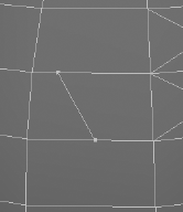
poly_hand_v2.mbshows the hand with the four fingers created.Now let's work on the thumb. First, you'll need to move a couple of edges to make room for where the thumb attaches to the hand. Select the three edges on the index finger side of the hand, and move them up toward the tip of the hand, as shown in Figure 4.21. This will create an elongated face to start the thumb.
You will use the Wedge Face tool to start the thumb. Select the elongated face. Right-click the object to display the marking menu, and choose Edge. Shift+select the edge on the left side of that face. (See Figure 4.22.)
Choose Edit Mesh → Wedge Face

To make the thumb itself, extrude that face first to 0.5 and then to 0.4 in Local Translate Z. The hand looks a bit awkward right now, especially the thumb area (see the second image in Figure 4.23).
Select the faces along the meaty part of the thumb, and move and rotate them to round out the hand. While you're at it, squeeze in the tips of the fingers a bit to point them all by selecting and scaling the very top face of each finger.
Select the pinkie finger edges (not faces), and scale them in to narrow the pinkie.
Select the edges that make up the knuckle of each finger (one by one), and scale them out in the X-axis to fatten the knuckles a bit. Your results should be similar to Figure 4.24.
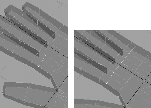
Now to add a bit more detail to the hand, you'll raise the knuckles. You'll have to create new vertices for the knuckles where each finger meets the hand. For this, the Split Polygon tool is perfect. Go back into Object mode (F8) and select the hand. Choose Edit Mesh → Split Polygon Tool. Your cursor will change to a sharp triangle. Use it to select a point on the hand where the index finger starts. Click the opposite edge on that face along the back of the hand. A line will be drawn between the two points (the first image in Figure 4.25).
If you press Enter, that line becomes a single new edge on that face. While you have the Split Polygon tool active, select three more points along the back of the hand as shown (the second image in Figure 4.25).
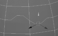
Press Enter to add four new edges and hence four new faces along the back of the hand for the knuckles. Select each of those new faces, and choose Edit Mesh → Poke Face to subdivide them into four triangles, with a vertex in the center. A special manipulator will appear. Use the Z translate handle to pull those middle vertices up to make knuckles (Figure 4.26).
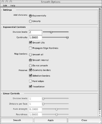
Now that you have a simple hand, you'll want to smooth out the mesh to make it less boxy. In Object mode, select the hand and press 2 to see a smoothed preview of what the hand will look liked once smoothed. Press 1 to exit smooth preview. Choose Mesh → Smooth
Click Smooth. Your hand should take on a smoother, rounder look—more like a real hand, and it should roughly resemble the preview. This time, however, you have altered the geometry and actually made the mesh smoother and given it a higher density of polygons. Notice all the nodes listed under INPUTS in the Channel box in Figure 4.28. This is because History has been on for the entire duration of this exercise. At any time, you can select one of those nodes and edit something—the extrusion of the pinkie, for example. You don't need to do any of this now, so with the hand selected, choose Edit → Delete By Type → History to get rid of all those extra nodes. (Feel free to edit any of those nodes through the Attribute Editor if you like.)


Save your file again. To verify that you've been working correctly, you can load the finished hand file (with its history intact) poly_hand_v3.mb from the CD.

As you saw with the hand, it became necessary to add more faces to parts of the surface to create various details. The hand takes on better form when time is devoted to detailing it. The hand shown in Figure 4.29 was begun using the previous steps, but it was detailed by creating faces using the tools discussed in this section, moving vertices, and adding fingernails. The most intricate of objects begin from the simplest models. You merely need time and effort to create them. Don't expect to be able to model intricately right from the start unless you already have modeling experience from another package. Recognizing how to detail models take a good amount of time and experience; just stay with it.
Maya provides several ways to add surface detail or increase a poly's subdivisions.

You can use the Add Divisions tool to increase the number of faces of a poly surface by evenly dividing either all faces or just those selected. Select the poly surface face, or faces, and choose Edit Mesh → Add Divisions. In the option box, you can adjust the number of times the faces are divided by moving the Division Levels slider. The Mode drop-down menu gives you the choice to subdivide your faces into quads (four-sided faces, as on the left of Figure 4.30) and triangles (three-sided faces, as on the right in Figure 4.30).

Figure 4.30. The Mode drop-down menu of the Add Divisions tool lets you subdivide faces into quads or triangles.
You can also select a poly edge to divide. Running this tool on edges divides the edges into separate edges along the same face. It will not divide the face; rather, you use it to change the shape of the face by moving the divided edges, as shown in Figure 4.31.
You use the Add Divisions tool to create regions of detail on a poly surface. This is a broader approach than using the Poke Face tool, which adds detail for more pinpoint areas.
Another way to create detail is to use the Split Polygon tool, which does exactly what its name suggests. As you've seen, when you choose Edit Mesh → Split Polygon Tool, your cursor changes to a triangle. Use this cursor to select two points along two edges of a face. This creates a straight line from the first to the second point, which serves as a new edge to divide the face into two halves as shown in Figure 4.32. Notice in the lower left in the Help line that there is a percentage readout that gives you the relative position of the tool along the current edge. You can use this readout to help position the new split.
Press Enter to create the new edge and faces or simply right-click to continue selecting new points for more edges to split the polygon face. When you're adding multiple new edges, right-clicking makes for a much faster workflow. Simply pick the first two points, and then right-click. The tool will still be active for the next split.
Using the Split Polygon tool is a flexible, accurate, and fast way to create surface subdivisions for your model.
This handy tool quickly adds edges to a poly selection, much in the same way as the Split Polygon tool, but it works much faster by working along the entire poly surface, along common vertices. The Insert Edge Loop tool automatically runs a new edge along the poly surface perpendicular to the subdivision line that you click, without requiring you to click multiple times as with the Split Polygon tool. We will use this tool in the Locomotive exercise shortly. You'll find it indispensable in creating polygonal models as it creates subdivisions quickly.
For instance, subdividing a polygonal cube is quicker than using the Split Polygon tool. With a poly cube selected, choose Edit Mesh → Insert Edge Loop Tool. Click an edge, and the tool places an edge running perpendicular from that point to the next edge across the surface and across to the next edge, as shown in Figure 4.33. If you click and drag along an edge, you can interactively position the new split edges.
Much like the Insert Edge Loop tool, the Offset Edge Loop tool inserts not one, but two edge loop rings of edges across the surface of a poly. Edges are placed on either side of a selected edge, equally spaced on both sides. For example, create a polygon sphere and select one of the vertical edges as shown in Figure 4.34. Maya displays two dashed lines on either side of the selected edge. You simply drag the mouse to place the offset edge loops and release the mouse button to create the two new edge loops.

The Offset Edge Loop tool is perfect for adding additional detail symmetrically on a surface quickly.
The Combine function is important in cleaning up your models and creating a unified single mesh out of the many parts that form it. When modeling, you'll sometimes use several different polygon meshes and surfaces to generate your final shape. Using Combine, you can create a single polygonal object out of the pieces.
The Merge tool is important when you are creating a polygon model because it fuses multiple vertices that are at the same point into one vertex on the model. Frequently, when you are modeling a mesh, you will need to fold over pieces and weld parts together. Doing so often leaves you with several vertices occupying the same space. Merging them simplifies the model and makes the mesh much nicer to work with, from rigging to rendering.
In the following simple example, we will create two boxes that connect to each other along a common edge and then combine and merge them into one seamless polygonal mesh. To begin, follow these steps:

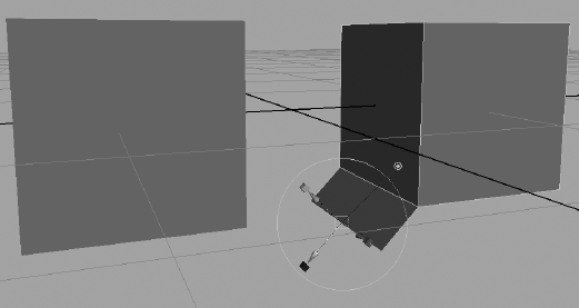
In a new scene, create two poly cubes and place them apart from each other, more or less as shown in Figure 4.35.
Select the bottom edge of the cube on the right that faces the other cube, and choose Edit Mesh → Extrude. Pull the edge out a little bit to create a new face as shown in Figure 4.36. This will be a flange connecting the two cubes. It is not that important how far you pull the edge out; you will be connecting the two cubes together by moving the vertices manually.
Select the first corner vertex on the newly extruded face, and snap it into place on the corner vertex of the other cube as shown in Figure 4.37. Remember, you can click the Snap To Points icon

Snap the other vertex to the opposite corner, so that the cubes are connected with a flange along a common edge, as shown in Figure 4.38.
Even though the cubes seem to be connected at a common edge, they are still two separate polygonal meshes. You can easily select just one of the vertices and disconnect the connective face of the two cubes. Now we need to merge the common vertices of the cubes. However, the Merge function will not work on vertices from two separate meshes. Therefore, you must first combine the cubes into a single poly mesh. The following steps continue our task:
Select the two cubes (one has the extra flange on the bottom, of course) and choose Mesh → Combine. This will make a single poly mesh out of the two cubes. You will now be able to use the Merge function.
Even though the cubes are now one mesh, you still have two vertices at each of the connecting corners of the cube on the left. As you can see in Figure 4.39, you can disconnect the flange by selecting just a single vertex at the corner and moving it. (Click on the vertex to select just one. Do not use a marquee selection as that will select both vertices at once.) If you move one of the corner vertices, just press the Z key to undo and return the flange to its connected position.
To merge the vertices at the corners, select both the vertices at the near corner (you can use a marquee selection), and then choose Edit Mesh → Merge. The two vertices will become one. Repeat the procedure for the far corner. Your connected cubes will become a single mesh with no redundant vertices. As you can see in Figure 4.40, if you select a vertex at a corner and move it, the cube and the flange both move and there will be no disconnect.


Note
If you need to separate a poly mesh back into its component meshes after you combine them, you can select the mesh and choose Mesh → Separate. You will not be able to use Separate if the mesh you have combined has merged vertices, however.
Keeping your meshes simple and organized is important to maintaining a clean and efficient workflow. You will notice fewer errors and issues with clean models when you animate, light, and render them. Combining meshes makes them easier to deal with, and Merge cuts down on unwanted vertices and makes working with the mesh cleaner and the surface easier. You will find that the more you model with polys, the more useful Merge becomes for creating great models.
Note
If the Merge function is not working on vertices in your work, make sure the model you are working on is a single mesh; merging vertices with this tool does not work on separate meshes. You must combine them into one poly mesh first.
Known as a poly knife in other 3D applications, the Cut Faces tool lets you cut across a poly surface to create a series of edges for subdivisions, pull off a section of the poly, or delete a section. (See Figure 4.41.) Select the poly object, and choose Edit Mesh → Cut Faces Tool. Click the option box if you want to extract or delete the section.
You can use the Cut Faces tool to create extra surface detail, to slice portions off the surface, or to create a straight edge on the model by trimming off the excess.

Select one or more faces, and choose Edit Mesh → Duplicate Face to create a copy of the selected face(s). You can use the manipulator that appears to move, scale, or rotate your copied face(s).
The Extract tool is similar to the Extrude tool, but it does not create the extra faces. Select the face(s), and choose Mesh → Extract to pull the faces off the surface (Figure 4.42). If the Separate Extracted Faces option is enabled, the extracted face will be a separate poly object; otherwise, it will remain as a part of the original.

You can use the Extract tool to create a hole in an object and still keep the original face(s). When you use this tool with the Split Polygon tool to make custom edges, you can create cutouts of almost any shape.
The Smooth tool (choose Mesh → Smooth) evenly subdivides the poly surface or selected faces, creating several more faces to smooth and round out the original poly object.
You can use a Maya feature called Artisan to sculpt polygonal surfaces. Artisan is a painting system that allows you to paint attributes or influences directly onto an object. With the Sculpt Geometry tool usage of Artisan, you paint on a polygon surface to move the vertices in and out essentially to mold the surface.
To access the tool in polygon modeling, select your poly object and choose Mesh → Sculpt Geometry Tool
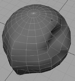
For more on sculpting, see the section "Using Artisan to Sculpt NURBS" toward the end of Chapter 5. The workflow is much the same as for sculpting with NURBS; the only difference when sculpting polygons is that the surface will behave in a slightly different manner when sculpted. Unlike the NURBS sphere, where the brush strokes give smooth curves in and out, a polygon surface is more jagged. Of course, if you create the poly with a large number of subdivisions, you will have a smoother result when using the Sculpt Geometry tool. (See Figure 4.43.)
This exercise will demonstrate the following polygonal modeling techniques:
Extrusion
Insert Edge Loop and Wedge Face tools
Object duplication
Pivot placement
CV curves and revolved surfaces
Complex model hierarchy
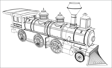
Now you are going to start to create a rather complex-looking object, an old-fashioned steam locomotive, using mostly polygons. (You will create one of the more detailed parts using NURBS patches in the following chapter.) You will use a schematic printout of the final model as a reference for your model. Because this is a complicated object, it's much better to start with good plans. This will involve some research, web surfing, image gathering, and/or sketching to get a feel for what you're trying to make.
To begin, create a new project for all the files called Locomotive, or copy the Locomotive project from the CD to your hard drive. If you do not create a new project, set your current project to the copied Locomotive project on your hard drive. Choose File → Project → Set and select the Locomotive.
Note
If you forget to set your project, your rendered images and scene files will be saved into your last project. When you create a new project, Maya automatically sets it as the current project.
Remember that you can enable Incremental Save to make backups at any point in the exercise.
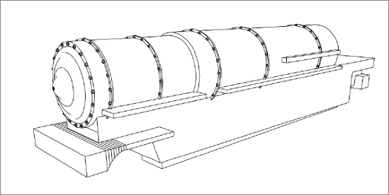
Now on to modeling a design already sketched and modeled. To begin, study the schematic printout of the final model included in the sourceimages folder of the project. This will help orient you to what we're building. Typically, you would be using sketches or downloaded images and such.
Beginning in Chapter 8, "Introduction to Animation," and following into Chapter 9, "More Animation!" you'll set up and animate the locomotive. When you're building any model, it is important to keep animation in mind, especially as it impacts grouping related objects in the scene hierarchy so that they will move as you intend. Creating a good scene hierarchy will be crucial to a smooth animation workflow; so throughout this exercise you'll use the Outliner to keep the locomotive's components organized as you create them.
The trick with a complex object model is to approach it part by part. Deconstruct the major elements of the original into distinct shapes that you can approach one by one. The locomotive can be broken down into five distinct objects, each with its own sub-objects:
Engine
Cabin
Wheels
Cowcatcher
You will model each part separately based on the detailed schematic in Figure 4.44.
The most prominent part of a steam locomotive is the steam engine, or boiler. Take a look at its shape. You can start with a simple cylinder and work from there. To start building the boiler, follow these steps:
Note
During this exercise, you will be switching a few times between the Polygons and the Surfaces menu sets to access the required functions.
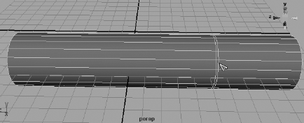
Create a polygonal cylinder by choosing Create → Polygon Primitives → Cylinder. Leave all the creation option settings at their defaults (do not enable Interactive Creation) to create the cylinder.
Rotate the cylinder 90 degrees in the X-axis to place it on its side. Scale the cylinder to about 1.8 in all axes. Then lengthen the cylinder until Scale Y is at about 8.9. You can either use the Scale manipulator or enter the values in either the Channel or Input boxes.
We will use the Insert Edge Loop tool mentioned earlier in this chapter to insert edges into the cylinder to make one end smaller. Select the cylinder, and choose Edit Mesh → Insert Edge Loop Tool
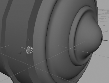
Right-click the cylinder, and choose Face from the marking menu. Select the end faces and scale them down a bit as in Figure 4.46. This gives us the main part of the boiler.
Make a new poly cylinder as before. Scale the cylinder to make it a flat plate and place it on the boiler. The cylinders will need to be scaled to fit snugly over the boiler as you see fit. This will give us a simple weld plate to provide the boiler with some simple detail. Choose Edit → Duplicate Special


Now we will create the boiler's front cap. Here we will use a NURBS curve to create a NURBS surface using a technique called Revolve, which we will discuss in more detail in the next chapter.
First, switch to the Surfaces menu and then follow these steps:

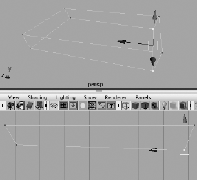
Choose Create → CV Curve Tool, and in the Side view panel, lay down CVs as shown in Figure 4.48 from the top of the curve down. Make sure you begin the curve about 1.5 units from the Z-axis so you can end the curve on the Z-axis line, as shown in Figure 4.48. When you have placed your last CV, press Enter to complete the curve. Don't worry if it is not exactly like the curve shown.
When you finish the curve in step 1, you should notice that Maya no longer displays its CVs in the panel. To display the CVs on a NURBS object, such as this curve, select the object and choose Display → NURBS → CVs. You can toggle the CVs off by choosing the same menu items again.
This curve is called the profile curve, and it will spin around to sweep a surface for the boiler cap. We need to revolve the curve around its bottom end to sweep a proper surface. Because you created the curve to end on the Z-axis, and the pivot point for the curve is by default at the origin, simply select the curve and while still in the Surfaces menu set, choose Surfaces → Revolve
Now that you have created the boiler cap, select the curve and move it in the scene. You will notice that the surface changes. This is how the history is displayed on the resulting surface. As we touched on earlier in the book, Maya's History functionality keeps a record of how the object was made, as long as the Construction History icon in the Status line is on.
We don't want history on the object, so select the boiler cap and choose Edit → Delete by Type → History. This will erase the history so the curve no longer affects the surface. Move the boiler cap into place at the front of the boiler. Scale it as needed to fit the cylinder's skinny end. (See Figure 4.49.)

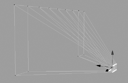
Now we will include a bit of detail by adding bolts to the front boiler cap and the weld plates. This will introduce you to the process of copying multiple objects into position automatically, otherwise known as copying into an array. To create the bolts, follow these steps:
Create a poly sphere by choosing Create → Polygon Primitives → Sphere
We need to duplicate this bolt many times to place it around the boiler cap and the weld plates. Instead of moving them into position one by one, we will create a circular array of bolts that we can group together and slap on the boiler. Move the bolt to the boiler cap, and place it on the left side of the boiler cap, halfway into the surface, as in Figure 4.50.
Enter Pivot Placement mode by pressing Insert (Home on a Mac, or fn + Home on a Mac laptop) to move the pivot of the bolt to the center of the boiler cap, and then exit Pivot Placement mode by pressing Insert (Home) again.
We will copy 19 more bolts to go around the boiler cap at 18-degree intervals, pivoting around the center of the cap. Select the bolt and choose Edit → Duplicate Special
Note
If you make the copies without moving the pivot point of the original bolt to the center of the boiler cap, none of the 19 copies will be arrayed into a nice circle around the boiler. They will end up in different configurations.
Notice that the option box does not close when you click Apply. Make sure to reset Duplicate Options back to normal. The next time you try to duplicate an object, you will get 19 instances of it if you don't reset it! In the option box, choose Edit → Reset Settings.
In the Outliner, select the 20 bolts and choose Edit → Group (or press the hot key combination Ctrl+G) to group them. Call the new group boiler_bolts or something similar to keep it organized. Center the pivot on the new group by choosing Modify → Center Pivot.
Select the boiler_bolts group, and duplicate it once to create another set of bolts you can place on the welding plates. You will have to scale the duplicated boiler_bolts group up a bit to make all the bolts fit around the weld plates. Repeat for the other plates as shown in Figure 4.52. Make sure you reset the duplicate options when you are finished to keep from making 19 copies next time around.


To check your work, or if you've just skipped ahead to this point, you can load the scene file locomotive_model_v1.mb from the Locomotive project on the CD.
Now we can tackle the base on which the boiler sits. Take a look at Figure 4.53, which shows a schematic view of the boiler sitting on the undercarriage of the train. Luckily, we have the luxury of referring to the final model here to visualize what we're modeling better.
Follow these steps to continue with the engine.
Create a poly cube and scale it to X = 2.7, Y = 2.95, and Z = 17.55. This will form the main length of the undercarriage you saw in the sketch in Figure 4.44, earlier in the chapter. Now we will use extrusions to create the ends. To make viewing easier while you create the undercarriage, you could select all the boiler elements and place them on a display layer to hide them as you work on this section. Alternatively, you could simply move the cube away from the boiler for the time being and move it back when you're finished.
Switch back to the Polygons menu, and right-click the cube you just created. Choose Face from the marking menu, and select the left end of the face. Choose Edit Mesh → Extrude. Using the Transform manipulator on the special Extrude manipulator, pull out the face slightly. Use the Scale Y manipulator (the green box) to scale the new face smaller in the Y-axis and move it up as shown in the left side image of Figure 4.54.
With the new face still selected, choose the Extrude tool again, and pull a new face out about 2.5 units to create a lip as shown in the right side image in Figure 4.54.
At the other end, we need to make a thinner lip. Select the poly object, and choose Edit Mesh → Insert Edge Loop Tool. Place a horizontal edge about one-fifth of the way down from the top edge. Choose the Extrude tool (from the Edit Mesh menu or from the Polygons tab of the Shelf, using the

Create three polygon cubes, and scale and position them at the right end of the undercarriage as shown in Figure 4.56. For now, just fit them in without worrying about overlapping or interpenetrating geometry.
For a finishing touch back there, we will round out the lip we created in step 4. Select the face on the end of the lip, and then right-click it again. This time choose Edge from the marking menu, and Shift+select the bottom edge as shown in Figure 4.57. Choose Edit Mesh → Wedge Face
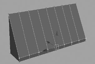
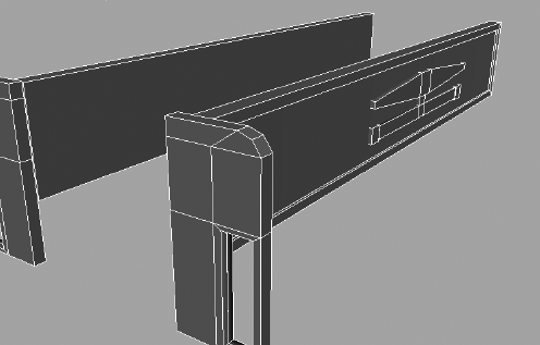
The next piece of the undercarriage fits on the left hand or front end and eventually attaches to the cowcatcher of the locomotive. Create a polygon cube, and scale it to X = 4.45, Y = 0.16, and Z = 4.0. Using the Insert Edge Loop tool, place nine equidistant subdivisions on the polygon slab, as shown in Figure 4.59. Notice that if you click and hold with the Insert Edge Loop tool, you can drag the location of the new edge line. This way you can more easily position the lines.
Select the bottom faces and move them down individually to create an arc, as shown in Figure 4.60. There is no need to extrude the faces; moving them one by one is fine. Place the new piece at the front of the undercarriage, as shown in Figure 4.61.
Let's tackle the cowcatcher. Create a polygon cube with eight subdivisions along its width. Scale the cube to 4.4 in X, 2.15 in Y, and 1 in Z. We will use this subdivided cube to pull vertices to make a cowcatcher shape. Enter Component Selection mode, pick the front top vertices, and move them down to make a wedge, as shown in Figure 4.62.
Select all the front vertices and the middle five back vertices along the bottom. Scale them in together in the Z-axis and then in the X-axis. Move them all forward to create the cowcatcher, as shown in Figure 4.63. Place the cowcatcher at the front of the undercarriage, as shown in Figure 4.64.
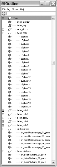
Place three poly cube slabs approximately as shown in Figure 4.65 for the boiler platforms. Group all these undercarriage pieces together and name them in a way that will help you stay organized. Also, make sure to group the parts of the boiler in a logical manner. The Outliner is shown in Figure 4.66 with the organization of the model so far.


You can load the scene file locomotive_model_v2.mb from the Locomotive project on the CD to check your work.
The fun parts of a steam locomotive are all the chimneys on top of the boiler. To create the main steam chimney and give it a revolving surface, follow these steps:
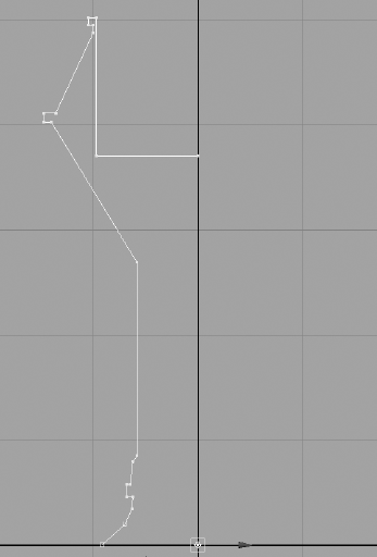
You will need to draw a profile curve for the smokestack/chimney. Choose Create → CV Curve Tool
This profile curve should now be about five units tall in the Z-axis in the Top view panel and have its pivot point at the origin. Enter the Surfaces menu set, select the curve, and choose Surfaces → Revolve
Change Axis Preset to Z. Also, at the bottom of the window, change Output Geometry to Polygons. We will not create a NURBS surface as we did before with the boiler cap, but instead will go for a poly revolve. Change Type from Triangles to Quads. This will create polygon faces that are rectangular rather than triangular.
Under Tessellation Method, select Standard Fit. Click Revolve, and you should have a chimney similar to the one shown in Figure 4.68. You may need to orient the chimney to fit the boiler properly if it is lying flat.
Delete the history by selecting the chimney and choosing Edit → Delete By Type → History. Place the chimney as shown in Figure 4.68. You can move the vertices at the bottom of the chimney to fit it to the round engine boiler as shown in Figure 4.69. You can also set to the Polygons menu.


Here is where I kick you out into the cruel hard world and make you create the remaining pieces for the engine boiler before we move on to the steam pumps, main cabin, wheels, and drive axles. You will find suggestions on how to create the individual pieces in this section. (We will set up the wheels in the animation chapters that follow.)
Study the following figures and graphics to get an idea of how to create these pieces using the Revolve tool and the other polygon toolsets used in this exercise and in this chapter. Figure 4.70 shows the extra pieces for you to build.
You can build the light box shown in Figure 4.71 from a polygon cube by adding subdivision edges with the Insert Edge Loop tool and extruding or moving faces in and out. The light itself is a simple cylinder set into this shape.


You can draw the two top boiler caps by drawing a profile curve and then revolving the boiler caps as we did for the chimney (Figure 4.72).

The piping and small tanks along the length of the engine boiler are simple cylinders placed in position, as shown in Figure 4.73.

The side panel details are simple poly cubes that have some faces extruded, with a few faces cut out (Figure 4.74).
You can load the scene file locomotive_model_v3.mb from the Locomotive project on the CD to go over the models firsthand and get a much closer look. You can use the scene file to help build the pieces shown in this section to complete the engine boiler and its details.
The following sections will cover the cabin and wheels.
All that remains now, as shown in Figure 4.75, are the main cabin, the wheels, and their drive system. We'll finish those parts in the following sections; we will set up, or rig, the wheels for animation in Chapter 9.
We'll start with the main cabin first. The cabin has two main sections, the cabin itself and the roof. Let's start with the roof and work our way down. Follow these steps:
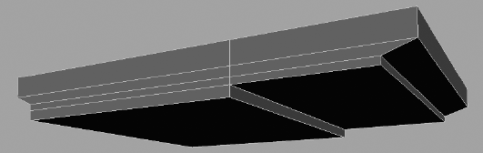
Make a poly cube and scale it so that X = 5.6, Y = 1, and Z = 7.7. Then select the front vertices (at the right side of the cube in the image here), and move them back a tad in Z to angle the edge a bit. Do the same to the rear bottom vertices, giving the cube a tapered look in the Z-axis (Figure 4.76).
We need to subdivide the cube. This time we will use the Add Divisions tool. Select the cube and choose Edit Mesh → Add Divisions
Right-click the cube to enter Component Selection mode, and choose Edge from the marking menu. Select the edges as shown here, and move them toward the back (to the left of the image in Figure 4.77) of the roof.
Using vertices, shape the roof to match the one in Figure 4.78.
Select the bottom two faces and extrude them down once. Select the back face again, and extrude that down one more time to match the shape shown in Figure 4.79.
Use the Insert Edge Loop tool to create more subdivisions along the long sides of the roof, and then move the corner vertices down to angle the side edges of the roof down a little bit to complete the roof, as shown in Figure 4.80.
The cabin is a simple cube that is subdivided with the Insert Edge Loop tool, as shown in Figure 4.81. To make the windows and the open back, select the faces that make up the openings in Component mode, and delete them.
Place the roof on top of the cabin and you're done! Figure 4.81 shows the completed main cabin from two sides.


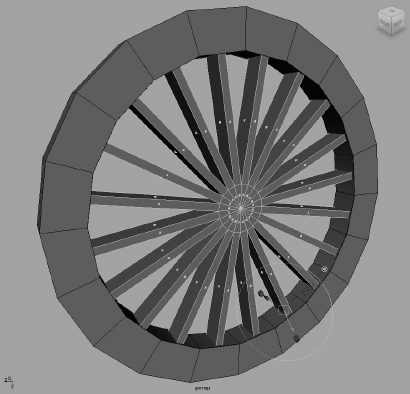
What's a locomotive without wheels? We will have two types of wheels: large ones that are driven by the steam pumps and a pair of small wheels in front of the boiler (see Figure 4.82).
To make the large wheels, follow these steps.
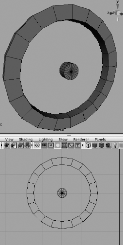
First, we'll create the outer rim of the wheels. Create a poly cylinder with Cap Divisions set to 5 in the option box and Axis Divisions set to 20. Scale the cylinder to X = 1.87, and squash it down to Y = 0.145. Turn it up on its side by rotating it 90 degrees in Z.
To hollow it out, select the inner faces on the caps, as shown in Figure 4.83, and delete them.
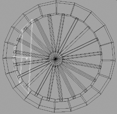
Now you should see a wheel rim similar to that in Figure 4.84. It is hollow on the inside, so you'll need to close the inside rim. Select the front edges of the inside rim, as shown in Figure 4.84, and choose Edit Mesh → Extrude. Extrude the edges toward the back side of the rim to close the inside rim.
The wheel spokes are next. You'll create the hub of the spokes with a poly cylinder scaled to X and Z = 0.25 and Y = 0.12, so it is slightly thinner than the rim. Rotate the hub 90 degrees in Z, and place it in the middle of the rim. It helps to snap both the hub and the rim to the same grid point to make sure they are centered and aligned (Figure 4.85).
Choose the Edit Mesh menu, and make sure that the Keep Faces Together option at the top of the menu is unchecked. Select the outer ring of faces on the hub, and extrude them out to meet the rim, as shown in Figure 4.86.
Next, create a poly cube and shape it as shown in Figure 4.87 to place it against the rim of the wheel on one side. This is where the steam drive's arm will connect to the wheel.
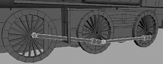
Group the pieces together and name the node large_wheel. Center the pivot on the hub by choosing Modify → Center Pivot. If your geometry is not perfectly symmetrical, the pivot may not center properly and you will have to enter Pivot mode (press Insert/Home) and move it manually to the center of the hub. If the top wheel node's pivot is not centered properly, animation will look weird. Duplicate and place the wheels as shown in Figure 4.88. Make sure they all face out properly and align as in Figure 4.88.
The wheel arms are next. These connect the wheels to the steam drive that runs the locomotive. You can use simple poly cubes to make the arms shown in Figure 4.89. Place them as shown, and then rotate the appropriate wheels (using the top large_wheel node) so that they align with the connecting plates. Notice that the arms go through the side panel detail you created earlier with the undercarriage. Group the arms together so that you have one group on either side of the train.


They sound like a trio of fifties rockabilly bands, but they are actually the last parts of the locomotive that we'll build in this chapter. The small wheels up front are the same as the larger wheels, except they do not have the connector plate and they have a solid background. You just need to copy one of the large_wheel groups and scale the top node down from 1.0 to 0.575. Delete the connector plate on the side and place a cylinder behind the wheel to close the back. Remember to group this new closing cylinder into the top node. Call the group small_wheel.
Figure 4.90 shows a small wheel in position.

The axle that holds the front wheels is easy to make using basic shapes. Using Figures 4.91 and 4.92 as guides, build the axle assembly using simple poly shapes made with primitives and a few subdivision tools and extrusions.
The steam pumps provide drive power to the wheel arms, which in turn rotate the wheels to move the locomotive. These pumps are located on the sides of the engine between the small wheels and the first of the large wheels. They connect down from the boiler and through a drive mechanism to the first set of large wheel on both sides.
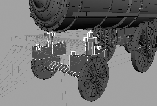
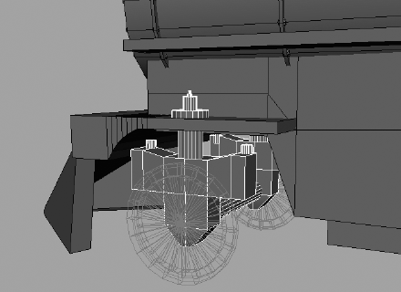
This drive mechanism rotates the first wheel, which drives the wheel arm to turn the other wheels on the engine. We will look at how to set up this relationship in the animation chapters later in the book. For now, let's make the steam pumps using simple poly objects, as shown in Figures 4.93 and 4.94.
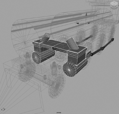

Figure 4.94. The drive mechanism is made of a couple of extruded cubes flanked by poly cylinder rods.

Connect the drive mechanism to the end of the wheel arm. Considering how your model will animate is an important aspect to modeling. This unit will animate in and out of the large pump cylinder, pulling the drive arm back and forth with it.
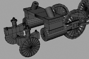
The completed model is shown in Figure 4.95.
Carefully go through your scene and name everything. OK, maybe not everything, but at least name the top nodes and important pieces of the model. Group items neatly so that everything makes sense. In Chapter 8 you will learn how best to organize the hierarchy of the model to suit animation needs.
Figure 4.96 shows the Outliner view of the organization of the final scene on the CD.
Open the scene file locomotive_model_v4.mb from the Locomotive project on the CD to compare with your work and to guide you as you complete your work. Comparing and contrasting are valuable learning aids. Sometimes figuring out how something was done by starting at the end and working backward (reverse engineering it) will give you a great deal of information.
Poly modeling lends itself nicely to a wide range of objects—practically anything you can think of, and some things you can't. Try modeling the following objects to fine-tune your skills and explore the toolset.

- Dining Room Table and Chairs
This is an easy place to start. There is good amount of leeway in the design, which will give you as much a challenge as you feel you can handle.
- Computer Monitor
With all its angles and overall surface details, a monitor makes for a great extrusion and face-editing exercise.
- Desk Lamp or Floor Lamp
This can be a quick exercise, so try to keep it highly detailed.
- Car
This exercise can be a real challenge, so keep it simple at first and increase the amount of detail the next time you try it. Try to keep your model to the overall shape of the car, and don't worry making doors and windows that actually operate. Try to model the faces so that different parts of the car have different faces. Use NURBS surface tools to create poly patches to form the body of the car.
In this chapter, you learned about the basic modeling workflows and how best to approach a model. This chapter dealt primarily with polygon modeling and covered several polygon creation tools as well as several polygon subdivision tools. You put those tools to good use building a hand and smoothing it out, as well as making a complex model of an old-fashioned steam locomotive. The latter exercise stressed the importance of putting a model together step by step and understanding how elements join together to form a whole model. You will have a chance for another model of that kind in Chapter 6, when you create a little red wagon.
Complex models become much easier to create once you recognize how to deconstruct them into their base components. You can divide even simple objects into more easily managed segments from which you can create a model.
The art of modeling with polygons is like anything else in Maya: Your technique and workflow will improve with practice and time. It is less important to know all the tricks of the trade than it is to know how to approach a model and fit it into a wireframe mesh.