
Now that you have a little more animation experience, you can get into some more involved animation practices and toolsets, taking the principles covered in this book and its examples further. Animation is a growing exploration, and you should use this book as a stepping-off point. For everything you're being exposed to here, there are many more techniques to discover.
Topics in this chapter include:
Skeletons and Kinematics
Skeletons: The Hand
Inverse Kinematics
Basic Relationships: Constraints
Basic Relationships: Set Driven Keys
Application: Rigging the Locomotive
In your body, your muscles move your bones and, as your bones move, parts of your body move. Bones are your internal framework.
In CG animation, a skeleton is an armature built into a 3D model that drives the geometry when the bones are moved. You insert a skeleton into a CG model and attach or bind it to the geometry. The skeleton's bones are animated (typically with rotations), which in turn move the parts of the geometry to which they are attached. By using a skeleton, Maya allows bending and deformation of the attached geometry at the skeleton's joints. A skeleton is, of course, useful for character work, but skeletons have many other uses. Any time you need to drive the geometry of a model with an internal system, such as fly fishing line or a tree bending in the wind, you can use skeletons. We will use them to drive the locomotive later in this chapter.
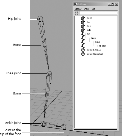
Skeletons rely on hierarchies. Bones are created in a hierarchical manner, resulting in a root joint that is the parent of all the joints beneath it in the hierarchy. For example, a hip joint can be the root joint of a leg skeleton system in which the knee joint is the leg's child, the ankle joint belongs to the knee, and the five toe joints are the ankle's children. (See Figure 9.1.)
Using skeletons, you can easily create an immediate hierarchical system with which to animate. Furthermore, pieces of geometry need not deform to be attached to a bone system. Objects can be grouped with or under joints. They move under their parent joint and rotate around that joint's pivot as opposed to their own pivot point.
A skeleton is really just a collection of grouped and properly positioned pivot points called joints that you use to move your geometry, whether it deforms or not. A bone is the length between each joint; bones only show you the skeletal system.
Inverse Kinematics (IK) and Forward Kinematics (FK) are the methods you use to animate a skeletal system. FK rotates the bones directly at their top joint to assume poses. This method resembles stop-motion animation, in which a puppet, along with its underlying armature, is posed frame by frame. With FK, the animator moves the character into position by rotating the joints that run the geometry.
The rotation of a joint affects the position of the bones and joints beneath it in the hierarchy (see Figure 9.2). If you rotate the hip up, the knee and ankle will swing up as if the character is kicking. If you rotate the knee down, the ankle pivots down as if this character is seated. This form of motion moves the way you would expect it to move in hierarchies and is, therefore, called Forward Kinematics.
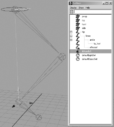
IK uses a more complex, but often easier, system of IK handles that are attached to the tip of a joint system. The corresponding base of the IK system is attached further up the skeleton hierarchy to a joint determined to be the root of that IK segment. It need not be the root joint of the entire skeleton, though.
The bones and joints in the IK chain are affected only by movement of the IK handle. When the handle moves, an IK solver figures out how to rotate all the joints to accommodate the new position of the IK handle. Moving an IK handle will cause the bones to rotate around their joints to accommodate a new position.
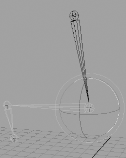
The effect is as if someone grabbed your hand and moved it. The person holding your hand is similar to an IK handle. Moving your hand causes the bones in your arm to rotate around the shoulder, elbow, and wrist. As you can see in Figure 9.3, the animation flows up the hierarchy and is, therefore, called Inverse Kinematics.
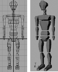
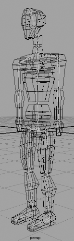
To understand skeletal hierarchy, take a look at a simple bi-ped (two-legged) character made of primitive blocks. He's called Block Man. (Surprise!) In Figure 9.4, each block represents a part of the body, with gaps between the blocks representing points where the body pivots.
The pivot of each block is placed to represent the appropriate joint location. For example, the shin's pivot is located at the knee. Each block is grouped up the chain so that the foot moves with the shin, which moves with the thigh, which moves with the pelvis.
The hands are grouped under the arms, which are grouped under the shoulders, and so forth down the spine to the pelvis. The head groups under the first neck block, and so on down the spine to the pelvis. The pelvis is the center of the body, which is known as the root of the figure.
The way this figure is grouped (see Figure 9.5) represents how the hierarchy of a character works for the most part. Each body part is attached and becomes the child of the part "above" it in the chain.
Load the file block_man_v02.mb from the Block_Man project folders on the CD for a good reference of the grouping structure. This file shows you what a skeleton hierarchy does.
In the Hypergraph Hierarchy window, choose Options → Layout → Freeform Layout to position the nodes in any way you want. To make selections easier, you can arrange the nodes as if they were on a body (see Figure 9.6). You can toggle between freeform and automatic, and your freeform layout will be retained.
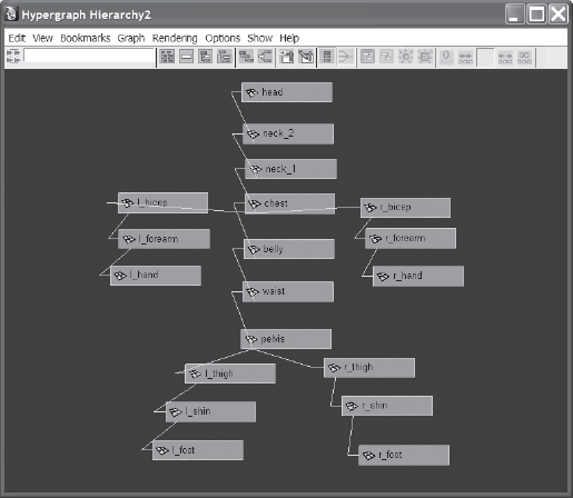
The basis of how the block man is laid out and grouped is what skeletons are all about. Skeletons make character animation easier by automating, at the very least, the hierarchy and pivot placement described earlier.
You'll use the block man to create a skeleton. Load block_man_v01.mb from the Block_Man project. This is the same as block_man_v02.mb, but this version is not grouped.
Maximize the Front View window. Switch to the Animation menu by using the drop-down menu or by pressing F2.
Activate the Joint tool by choosing Skeleton → Joint Tool. Your cursor will turn into a cross.
Click in the middle of the pelvis to place the first joint, the root joint of the skeleton.
Shift+click up to the space between the pelvis and the waist.
Note
The joint display size in your Maya window may not match those shown in the book. This is not a problem; however, you can change the joint sizes by clicking Display → Animation → Joint Size.
By pressing Shift as you click, you create a joint in a straight line from the last joint placement. A bone is created between the two joints as a visual guide to the skeleton. The placement of the joints depends on the active view, so placing a second joint in a different view may place the joint in an awkward location.
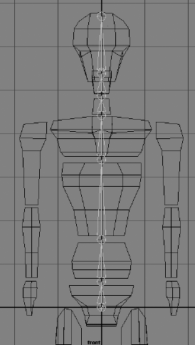
Click more joints up the spine at the gaps between the body parts as shown. (See Figure 9.7.)
You need to start a new branch of joints leading into the legs and arms. You'll begin with the arms. With the Joint tool still active, press the Up arrow key three times to move up the hierarchy of joints to the one between the neck and chest parts.
Note
Pressing the Up arrow key takes you up one node in a hierarchy. Pressing the Down arrow key takes you down one node in a hierarchy. This approach also applies to skeletons, because they are hierarchies.
Stay in the front view. Now, from this joint between the neck and chest, click to place a joint at the top of the right bicep at the shoulder. Click down to create joints at the elbow, the wrist, and the tip of the model's right hand.
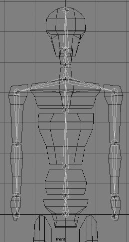
Press the Up arrow to pick walk up the chain to the neck/chest joint, and repeat step 7 to create the joints for the left arm as shown in Figure 9.8.
To start another string of joints in the first leg, pick walk back up the skeleton until you're at the pelvis root joint. (See Figure 9.9.)
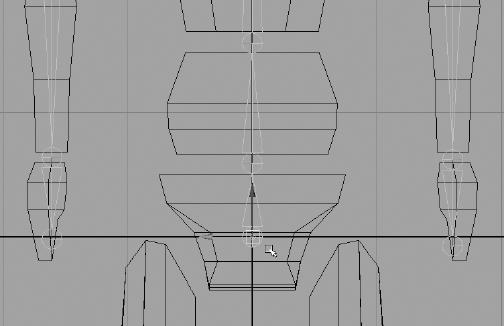
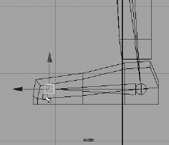
From the root joint at the pelvis, click to create a joint at the tip of the right thigh and work down to the knee and ankle. Place the ankle joint halfway down the foot, as shown in Figure 9.10, as opposed to the gap between the shin and the foot. Press the spacebar to return to the four-way view from the front view, and maximize the side view. Click to create a joint at the tip of the foot. This allows you to place a joint in the proper axis in the side view. (See Figure 9.11.)
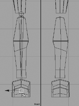
Return to the front view, and press the Up arrow to get back to the pelvis joint. Repeat step 10 to create joints for the left leg. After you place your joints, press Enter. Figure 9.12 shows the skeleton.
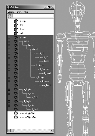
You now have a full skeleton for your character. To attach the geometry, all you need to do is parent the body parts under their appropriate joints. Before you get to that, take a few minutes and name all the joints in the Outliner to make the scene easier to manage. Figure 9.13 shows the names used in the project on the CD.
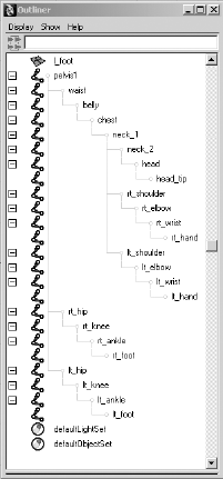
You can also load the block_man_skeleton_v01.mb file from the Block_Man project to get to this point.
To parent the block man's geometry to the skeleton, follow these steps:
Starting with the right foot, parent it under the right ankle joint (rt_ankle) by MMB+clicking and dragging it to rt_ankle in the Outliner or the Hypergraph. You don't want to parent it under the right foot joint (rt_foot), because you need the foot geometry to pivot with that foot bone and inherit the rotations from the ankle above it. Parent the left foot under the left ankle (lt_ankle). (See Figure 9.14.)
Parent the rest of the body parts (see the following list) under their respective joints, as shown in Figure 9.15.
Shins under the knees and thighs under the hips
Hands under the wrists, and forearms under the elbows
Biceps under the shoulders
Head under the head joint (the joint between the head and the top neck geometry)
The top neck geometry under the joint between the two neck pieces
The bottom neck geometry under the joint between the chest and the neck
The chest under the joint between the chest and belly pieces
The belly under the joint between the belly and waist


A walk cycle is an animation that takes the character through a few steps that can be repeated many times so that the character seems to be taking numerous steps. In a cycle, make sure the position of the first frame matches the position of the last frame so that when the animation sequence is cycled, no "pop" occurs in the motion at that point.
Now, try animating this character's walk cycle using FK on the skeleton. You'll find the workflow straightforward, as if you were adjusting positions on a doll.
Load the block_man_skeleton_v02.mb file from the Block_Man project on the CD for the properly grouped model and skeleton.
Use the key poses in the following figures to guide you in animating the body as it walks. You'll key at five-frame intervals to lay down the gross animation. You can go back and adjust the timing of the joint rotations in the Graph Editor to make the animation better. The white leg and arm are behind the body, farther from the camera.
This animation is also called pose animation because you are posing the character from keyframe to keyframe.
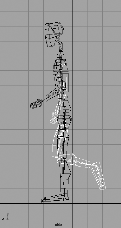
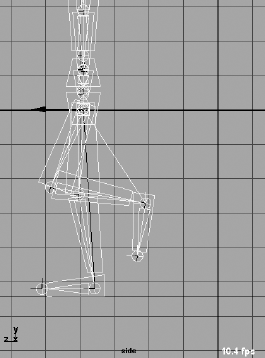
Figure 9.16 shows the character's starting position. Here you'll set a key for this position and then begin the walk cycle by moving the joints into their second position and keyframing that.
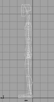
At frame 1, set a key for the rotation of all the joints. The easiest way is to select all the joints in the Outliner or the Hypergraph. With this pose animation, make sure all the joints are keyframed at every step, even if Auto Keyframe is turned on. Also set a position keyframe for just the pelvis joint.
A quick way to select all the joints, and only the joints, is to filter the Outliner view to show only joints. In the Outliner, choose Show → Objects → Joints. To reset the Outliner, choose Show → Show All.
Go to frame 5. Rotate the back leg (the block man's right, white leg) back, and rotate the foot to make it level again. Lower the body (select and move the pelvis joint) to line up the back heel with the ground. This will keep the man on the ground as he goes through the walk cycle, although he won't actually move forward yet.
Rotate the near leg (the man's left leg) forward, bend the knee, and pivot the foot up a bit.
Rotate the back arm forward, and rotate the near arm back (opposite from the legs). Bend the arms at the elbows.
Bend the man forward at the waist, bend neck_1 forward, and tilt the head back up to compensate a little. Figure 9.17 shows the pose at this point.
Select everything in the Outliner, and set a rotation key. You're setting a pose for all the joints, which will ensure that all body parts are in synch.

If you don't key everything every step of the way, some parts of the body will not key with Auto Keyframe properly because the last time they moved might have been two steps previous.
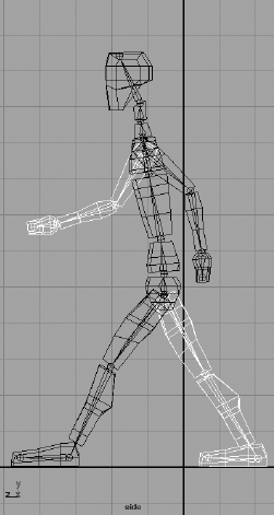
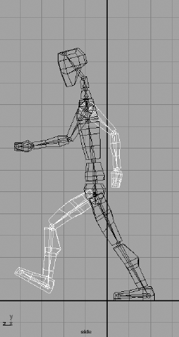
Figure 9.18 shows the position you'll keyframe at frame 10; it's approximately midstride for the first leg.
Go to frame 10. Rotate the back leg out farther, and level the foot. Lower the body to place the man on the ground.
Rotate the front leg out, straighten the knee, and flatten the foot to place it on the ground. This is midstride. Swing the arms in their current direction a touch more. Bend the torso forward some more. Make sure you set a key for all the joints.
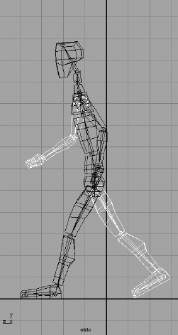
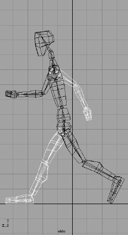
Figure 9.19 shows the position you'll keyframe at frame 15. At this point, the character begins to shift his weight to the front leg as it plants on the ground, and the character also begins lifting the back leg.
Go to frame 15. Rotate the front leg back toward the body, and raise the body as the man steps to keep the front foot flat on the ground. Rotate the back knee up to lift the foot, and rotate the foot down to make him push off the toe.
Start swinging the arms in the opposite direction. Start straightening the torso back up, but bend the head forward a bit.
At frame 20, the man will shift all his weight on the front leg and move his body over that leg, lifting his rear leg to begin its swing out front to finish the stride. Figure 9.20 shows the pose.
Rotate the front leg almost straight under the man, and lift up the body to keep the front foot on the ground. Lift the rear leg and swing it forward.
Straighten the torso and keep the arms swinging in their new direction. Key all the joints.
Now the man will swing his whole body forward, pivoting on the left leg (the dark one) to put himself off center and ready to fall forward into the next step. Figure 9.21 shows the pose.
Go to frame 25.
Rotate the front (dark) leg back behind the man, and swing the white leg up and ready to take the next step. Lower the body to keep the now rear foot (the dark one) on the ground.
Use Figure 9.22 as a guide for creating the next pose. Notice that it is similar to the pose at frame 10 (in Figure 9.18). As a matter of fact, the only major differences are which leg and arm are in front. Everything else should be about the same. You'll want some variety in the exact positions to make the animation more interesting, but the poses are much the same.
You've finished a set of poses for the character's first step. The next set of poses for your walk cycle will correspond to the first set, but now the other leg and arm correspond to these positions. For example, you animated the left leg taking a step forward in the first series of poses. The next series of poses will have to do with the right leg. The pose at frame 35 corresponds to the pose at frame 15. Frame 40 matches frame 20. You can start a new series of poses with the left leg.
Once a 30-frame section is complete, you will need to return to the animation through the Graph Editor. Adjust all the keyframes that you set at five-frame intervals to make the animation more realistic. Right now you have only the gross keyframes in place, so the timing is off. Your next step is to time the frames properly. This is ultimately a matter of how the animation looks to you.
Logistically speaking, some poses take a little less time to achieve than the evenly spaced five frames you used. For example, achieving the second pose from the start position should take four frames. The third pose (see Figure 9.18 earlier in the chapter) from frame 5 to frame 10 should take four frames. The next frame section originally from frame 10 to 15 (the fourth pose; see Figure 9.19 earlier in the chapter) should also take only three frames. To accomplish this easily, follow these steps:
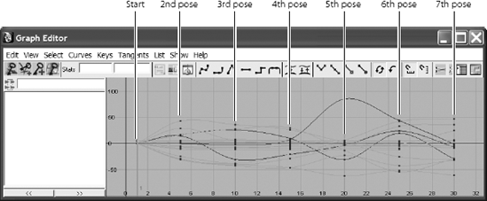
Select the top node of the skeleton (the pelvis), and open the Graph Editor. On the pelvis node in the left side of the Graph Editor, Shift+click the plus sign to open the entire tree of nodes beneath the pelvis. All the animated channels will show their curves to the right as shown in Figure 9.23.
Marquee-select all the keyframes on the curves beyond frame 1, but not including those at frame 1. Press the W key to activate the Translate tool. Shift+MMB+click in the Graph Editor (so you can move only in one axis), and drag the keys horizontally to move them all 1 unit (frame) to the left. All the keyframes move, and the second pose now goes from frame 5 to frame 4.
Deselect the keys now at frame 4 by holding down the Ctrl key (you will also use the Ctrl key on a Mac) and marquee-deselecting all those keys at frame 4. Shift+MMB+click and drag the remaining selected keys 1 unit to the left again. The third pose goes from being at frame 9 to frame 8.
Deselect the keys now at frame 8 and Shift+click and drag the other selected keys to the left two frames so that the fourth pose animates between frame 8 and frame 11. Deselect the frame 11 keys, and move the rest over two frames to the left again so that the next section runs from frame 11 to frame 14. The following section should go from frame 14 to frame 18. The final section should go from frame 18 to frame 22. Figure 9.24 shows the new layout for the curves.
Continue to set and adjust keys for another cycle or two of the walk. The majority of time spent in animating something like this involves using the Graph Editor to time out the keyframes to make the animation look believable. Also try offsetting some of the arm rotations a frame to the left or right to break up the monotony that arises from having everything keyed on the same frame.

Load the file block_walk_v01.mov or block_walk_v01.avi of this walk cycle from the Images folder of the Block_Man project on the CD to see the animation in motion. It's a rough cycle, and you have to keep adjusting the character's height to keep the feet on the ground. This is where IK comes in handy, as you'll see later in this chapter. Also, the file block_man_skeleton_walk_v01.mb in the Block_Man project has the keyframed cycle for you to play with and continue animating.
This walk cycle animation is more about getting comfortable with keyframing and skeletons than it is about creating great walk cycles, so take some time to practice and get better. Animating walk cycles is a good way to hone your animation skills. Several great books are devoted to character rigging and animation alone, and you can research the field for ways to become more proficient. But keep in mind that movement and timing are what make animation good, not the setup or the model.
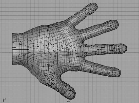
For another foray into a skeletal system, you can give yourself a hand—literally. You'll use a skeleton to deform the geometry and animate it as a hand would move.
Load the file poly_hand_skeleton_v01.ma from the Poly_Hand_Anim project on the CD. The hand is shown in Figure 9.25.
You'll use it to create a bone structure to make the hand animate. This is called rigging.
To create the first bones of the hand, follow these steps:
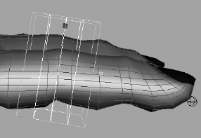
Maximize the Top View window. Switch to the Animation menu by using the drop-down menu or by pressing F2.
Activate the Joint tool by choosing Skeleton → Joint Tool. Your cursor will turn into a cross.
Click at the base of the wrist to place the first joint. This will be the root joint of the hand.
Shift+click the bottom part of the palm.
Place joints down through the thumb from this second joint according to the corresponding bones in Figure 9.26.
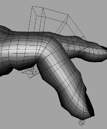
To start another string of joints into the palm, press the Up arrow key four times until you're at the second joint at the base of the palm.
The next joint you place will be a branch from this joint. Place that joint in the middle of the palm. Place another joint up farther along the palm, and then branch it out to the index finger. Press the Up-arrow key to return to that upper palm joint, and start a new branch into the middle finger. Repeat this procedure to place joints for the remaining fingers as shown in Figure 9.27. With these joints placed, you have a simple skeleton rig for the hand. This rig allows you quite a bit of hand and finger movement.


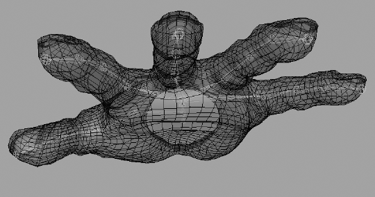
Check the other views (see Figure 9.28) to see where you need to tweak your joint positions to fit the hand. Ideally, you want the joints to be set inside your intended geometry in the same way that real bones are laid out.

To position the joints, you can use either of two Maya tools: Move or Move Pivot. First, you'll try the Move tool. Select the tip joint for the pinkie. It needs to be lowered into the pinkie itself. Select the Move tool (press W), and move it down into the tip of the pinkie. Now move on to the top pinkie knuckle. Notice that if you move the knuckle, the tip will move as well. That's not such a great idea.
Instead, it's best to move joints as pivots. Because joints are nothing more than pivots, go into the Move Pivot mode (press the Ins key, or the Home key on a Mac) to move joints. Select the top pinkie-knuckle joint, and move it with Move Pivot instead (press Ins or Home). Only the joint moves, and the bones adjust to the new position. Set the positions on the remaining joints to be inside the hand properly, as shown in Figures 9.29 and 9.30.

An integral part of rigging a character or an object with a skeleton is binding, also known as skinning. Binding is another way to attach geometry to a skeletal system. With the block man, you directly attached the whole pieces of geometry to the bones through parenting; whereas binding involves attaching clusters, or groups of vertices or CVs, of the geometry to the skeleton to allow it to deform the model. This is typically how skeletons are used in character animation work. (For more on grouping and parenting, refer to the Solar_System exercise in Chapter 2, "Jumping in Headfirst, with Both Feet.")
The basic technique of binding a character is easy. However, Maya gives you tremendous control over how your geometry deforms.
Binding is, in theory, identical to the Lattice deformer you saw in Chapter 5, "Modeling with NURBS, SubDivisions, and Deformers." A lattice attached to an object exerts influence on parts of the model according to the sections of the lattice. Each section affects a NURBS surface's CVs or a polygon surface's vertices within its borders and, as a section of the lattice moves, it takes those points of the model with it.
Skeletal binding does much the same thing. It attaches the model's points to the bones and, as the bones pivot around their joints, the section of the model that is attached follows.
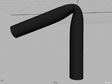
Figure 9.32. Smooth bind of the cylinder shown in Figure 9.31. The crease is smoother, yet less defined.
By attaching vertices or CVs (depending on your geometry) to a skeleton, you can bend or distort the geometry. When a bone moves or rotates about its joint, it pulls with it the points that are attached to it. The geometry then deforms to fit the new configuration of the bones bound to it.
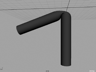
You can directly bind geometry to a skeleton in two ways: using Smooth Bind and using Rigid Bind. You can indirectly deform geometry using deformers and lattices attached to skeletons, but here you'll use the direct methods. Figure 9.31 shows a rigid bind, and Figure 9.32 shows a smooth bind.
Create a tall NURBS cylinder, with a span of 16 or more. The more spans you have in the deformable model, the better it will bend. Duplicate the cylinder, and move it over in your window. Now in the front view, create a four-bone (five-joint) skeleton that starts at the bottom of the first cylinder and goes straight up the middle, ending at the tip. Duplicate the skeleton, and move it to the center of the second cylinder.
A rigid bind is the simpler of the two, because only one surface point (vertex or CV) is affected by a joint at a time. A rigid bind groups the CVs of a NURBS or the vertices of a polygon into joint clusters that are then attached to the bones. No one surface point is influenced by more than one joint.
Therefore, bending a model about a joint with a rigid bind yields a more articulate crease than a smooth bind, which allows more than one joint to affect the CV or vertex, resulting in a more rounded and smooth bend.
To create a rigid bind, select the first skeleton and Shift+click its cylinder. In the Animation menu, choose Skin → Bind Skin → Rigid Bind
In the option box, you'll find that almost everything you need is already set to the default. The Bind To parameter lets you rigid bind the entire skeleton to the geometry or rigid bind only the joints selected. Using Selected Joints gives you the option of using just part of a skeleton system to rigid bind, which also gives you flexibility in how your rig affects the model. You'll leave that option on Complete Skeleton to attach the whole thing.
Click the Color Joints check box to set a different color for each joint in the bind, which can make for an easier workflow. The Bind Method parameter deals with how the points in the model will be attached. The default, Closest Point, organizes the points into skin point sets according the joint to which they are closest. They are then assigned to be influenced by that joint only.
The Partition Set option lets you define your own points before you bind and select which points are set to which joints. If you define a partition set for each joint you have, Maya assigns each set to the nearest joint. For example, you can define some points at the top of the surface to be a part of a set controlled by a joint in the bottom part. Closest Point is the best option for most work.
Using the defaults and turning on Color Joints, click the Bind Skin button in the option box. The root of the skeleton is now selected and the cylinder turns magenta, signifying it has input connections (such as history).
A smooth bind allows a joint to influence more than one skin point on the model. This allows areas of the model farther from the joint to bend when that joint rotates. Joints influence points to varying degrees between 0 and 1 across the surface, decreasing in influence the farther the point is from the joint. The multiple influences on a point all need to add up to 1 across all the joints that influence it. Maya automatically generates the proper influence amounts upon binding, although the animator can change these values later.
To create a smooth bind, select the second skeleton and its cylinder and choose Skin → Bind Skin → Smooth Bind
In the option box, you'll find the familiar Bind To parameter. You will also find, under the Bind Method drop-down menu, the options Closest in Hierarchy and Closest Distance. Choosing Closest in Hierarchy assigns the skin points to the nearest joint in the hierarchy. This is most commonly used for character work, because it pays attention to the way the skeleton is laid out.
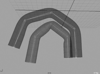
Figure 9.33. Rigid and smooth bound cylinders. The smaller cylinder is rigid bound, and the larger is smooth bound.
For example, a surface point on the right leg would not be affected by the thigh joint on the left leg simply because it is near it on the model. Closest Distance, on the other hand, disregards a joint's position in the hierarchy of the skeleton and simply assigns influences according to how far the point is from the joint.
Max Influences sets a limit on how many joints can affect a single point. Dropoff Rate determines how a joint's influence diminishes on points farther from it. For example, with Smooth Bind, one shoulder joint can influence, to varying degrees, points stretching down the arm and into the chest and belly. By limiting these two parameters, you can control how much of your model is pulled along by a particular joint.
Using all the defaults is typically best. So click Bind Skin in the option box to smooth bind your second cylinder to the bones.
Bend both cylinders to get a feel for how each creases at the bending joints. Figure 9.33 shows the difference.
If you want to do away with your binding, select the skeleton and its geometry and choose Skin → Detach Skin. The model will snap to the shape it had before the bind was applied and the joints were rotated. It's common to bind and detach skeletons several times on the same model as you try to figure out the exact configuration that works best for you and your animation.
If you need to go back to the initial position of the skeleton at the point of binding it to the model, you can automatically set the skeleton back to the bind pose after any rotations have been applied to any of its joints. Simply select the skeleton and choose Skin → Go to Bind Pose to snap the skeleton and model into the position they were when you bound them together. It is also best to set your skeleton to the bind pose whenever you edit your binding weights.
A MODELING TRICK USING A SKELETON
An easy way to create bends and creases in a model is to create the surface without the bend and use a skeleton to deform it the way you want. You can then detach the skin and bake the history so that the surface retains its deformation but loses its connection to the skeleton. Bind your geometry to the skeleton chain using Smooth Bind or Rigid Bind. Bend the skeleton to deform the geometry, and then choose Skin → Detach Skin
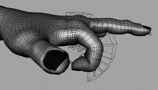
Because you'll want definitive creases at the finger joints, you'll use Rigid Bind for the hand.
Load your hand and positioned skeleton, or use the file poly_hand_skeleton_v02.ma from the Poly_Hand_Anim project on the CD. Now follow these steps to Rigid Bind the hand:
Select the skeleton's root at the wrist, and Shift+click the top node of the hand. If you are using the file from the CD, select the hand's top node (handTopNode) to make sure you select the fingernails as well, as shown in Figure 9.34.
Choose Skin → Bind Skin → Rigid Bind

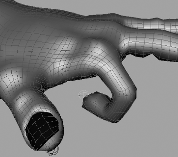
Select some of the finger joints and rotate them. Notice how the model creases at the knuckles, as shown with the index finger in Figure 9.35. If you rotate far enough, the model will fold in over itself.

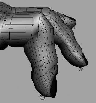
Having a rigid bind doesn't mean your creases always have to be this hard. With flexors (basically lattices, as discussed in Chapter 6, "Building the Red Wagon"), you can smooth out specific areas of a joint for a better look. This is useful at shoulder joints or hip joints, where a crease such as on an elbow is not desired. In this case, it will help smooth out the knuckles so the geometry doesn't fold over itself, as in the previous graphic.
Choose Skin → Go to Bind Pose to reset your skeleton.
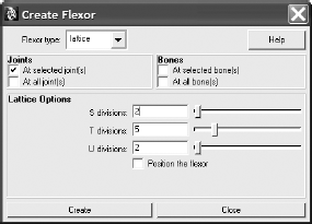
Select the middle knuckle of the index finger, and choose Skin → Edit Rigid Skin → Create Flexor to open the option box for Create Flexor (Figure 9.36).
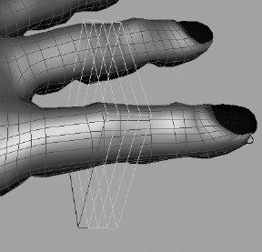
You'll notice that these options are similar to the lattice you created in Chapter 6 to edit the model. You can adjust the number of divisions later through the Attribute Editor, so you don't need to know exactly what you require before you create the flexor. Click Create to display a lattice at the joint position, as shown in Figure 9.37.
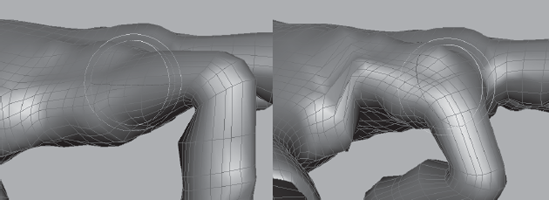
In the Outliner, drill down to the jointFfd1LatticeGroup node now attached under that knuckle joint in the hierarchy. Select the lattice as well as its base so you can adjust the size and, if need be, position of the flexor, just as you did on the lattice work earlier. Resize the flexor so that it better conforms to the knuckle, and elongate it so that it covers more of the finger, as shown in Figure 9.38.
Scaling and positioning the flexor (when both lattice and base nodes are selected) will make the joint bend smoother, without affecting it more than is necessary. By elongating the flexor here, you smooth out the knuckle's bend, prevent the polygons from bending over each other, and still maintain a crisp crease, as shown in Figure 9.39.
Create flexors for the other knuckles that will need them. Be sure to scale the flexors to make the most efficient use of them and fit them only where they need to be fitted. Figure 9.40 shows how the finger reacts when bending with flexors at each joint.
For reference, the scene poly_hand_skeleton_v03.ma from the Poly_Hand_Anim project on the CD has the hand rigid bound with flexors on one finger. Start with it to create flexors for the rest of the fingers, and animate the hand making some sign language positions, grabbing a pencil, or pressing a button.
Now try skinning the hand with Smooth Bind.
Load your prebound hand or poly_hand_skeleton_v02.ma from the Poly_Hand_Anim project on the CD. Now follow these steps to smooth bind the hand:
Select the root at the wrist and the top node of the hand (if you are using the hand from the CD, make sure you have the nails as well). Choose Skin → Bind Skin → Smooth Bind.
Try rotating some of the knuckle joints to see how the fingers respond. Go back to the bind pose when you're done.
Rotate the middle knuckle of the index finger down. Notice how the knuckle gets thinner the more you bend the finger there. Go to the top knuckle of the index finger and rotate that joint. Notice that part of the hand moves with the finger. This is again exaggerated because the hand is polygonal, so its deformations seem more severe than a NURBS model of the same hand. Figure 9.41 shows the result of bending at the index finger.
You usually edit a smooth bind by painting skin weights. Because points on the model are influenced by multiple joints in a smooth bind, you will need to adjust just how much influence is exerted by these joints on the same points.
Make sure you are in Shaded mode (press 5). Select the hand, and then choose Skin → Edit Smooth Skin → Paint Skin Weights Tool
Note
You paint skin weights on the affected geometry and not on the joints themselves, so you need to select the model and not the skeleton before invoking this tool.
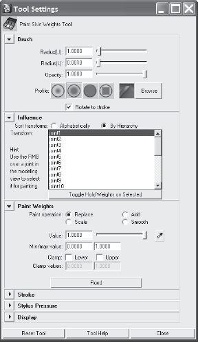
Your hand should now turn black, with a bit of light gray at the wrist. The option box will appear, listing the joints that are connected to the hand, as shown in Figure 9.42.
The color value (between white and black) determines how much binding influence the selected joint in the option box is exerting on that part of the geometry. It's best to name your joints properly so that selecting from this window is easier and more intuitive. If you loaded the file from the CD, you'll need to name the joints yourself to organize the scene and make working with it easier.
In the option box, make sure the Paint Operation button under the Paint Weights section is set to Replace. Change the Value slider to 0. In the Brush section, the Radius(U) and Radius(L) govern the size of your brush. Make sure the Opacity slider is set to 1.
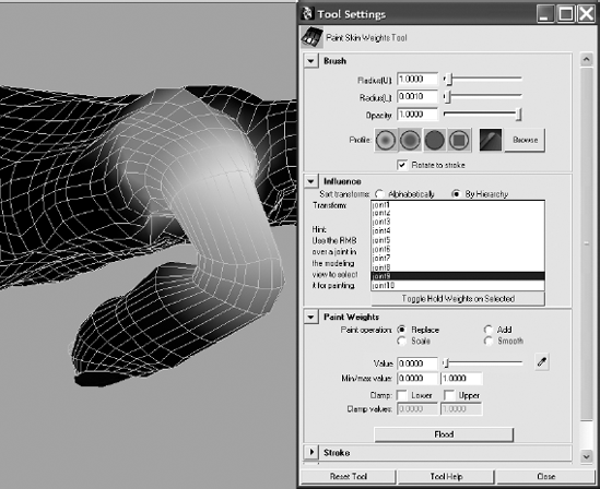
Click and paint the black value around parts of the hand and palm that should not be affected by the index finger bending at its top knuckle, as shown in Figure 9.43.
Note
Skin weights must always be normalized in a smooth bind, meaning the values have to add up to 1. When you reduce the influence of a joint on an area of the surface, the influence amount is automatically shifted to other joints in the hierarchy that have influence over that area, so those joints are now more responsible for its movement.
Smooth out the area where it goes from white to black. In the Tool Options window, set Paint Operation to Smooth. Rick-click to smooth the area around the knuckle for a cleaner deformation. Your index knuckle should now bend beautifully.
You can exit the Paint Skin Weights tool by selecting another tool (press W for Translate, for example), and your view will return to regular Shaded mode. Try bending the rest of the fingers and painting their influences and then animate the hand, making gestures or grabbing an object using FK animation to set keys on the rotations.
Note
When you paint weights on polygons, keep in mind that you will be painting using the UVs. You might need to re-create the UVs of a polygonal mesh with a UV projection map for the Paint Weights tool to function properly, especially when importing and exporting the weight maps from one mesh to another (a procedure you won't encounter until later in your Maya experience).
The scene poly_hand_skeleton_v04.ma from the Poly_Hand_Anim project on the CD has the hand smooth bound with painted weights on the index finger for your reference. Try painting the other knuckles as needed for your animation.
Note
Rigging work is essential for getting a good animation from your model. In a professional shop, it usually falls under the domain of a technical director (TD) who oversees the set up of characters and may also model their geometry. The more time I spent rigging scenes for the animators when I was a TD on the television show South Park, the easier and faster they were able to accomplish their animations.
With IK, you have tools that let you plant a foot where it needs to be so you're not always moving the skeleton or model to compensate and keep the heel in place.
For legs, IK is nothing short of a blessing. There is no clearly preferable workflow to suggest when dealing with rigging arms and hands, however. Many people use IK on hands as well, but it can be better to animate the legs with IK and animate every other part of the body with FK. IK is best used when parts of the body (such as the feet) need to be planted at times. Planting the hands is not necessary for a walk cycle, and having IK handles on the arms may create additional work while animating them.
Now it's back to the block man. Switch to that project and load your version or the block_man_skeleton_v02.mb file from the Block_Man project on the CD.
You will create an IK chain from the hip to the ankle on each foot. Creating the IK from the hip to the toe will not work as well.
Because IK automatically bends the joints in its chain according to where its end effector, or IK handle, is located, it has to choose which way to bend at a particular joint. To prevent IK from choosing the wrong way, you will first nudge the knees slightly to let the IK solver know which way that joint is supposed to go. Follow these steps:
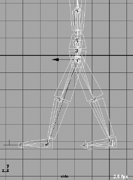
Select the two knee joints. In Pivot mode (press Ins; press the Home key on a Mac), move the knees a little bit forward to create a slight crook in the leg, as a natural knee would bend.
Open the IK Handle tool by choosing Skeleton → IK Handle Tool. Your cursor will change to a cross.
Select the start joint for the IK chain. This will be the root of this chain. Click the left thigh joint, and then pick your end effector at the heel joint. Repeat this procedure for the other leg. Figure 9.44 shows handles on both ankles.
If for some reason you can't manage to pick a joint for the IK tool, make sure that Show → Pivots is turned on in your view panel. Also, if you have difficulty seeing the handles, you can increase their size by choosing Display → Animation → IK Handle Size.
Move the IK handles around and see how the legs react. When you're done, reset the IK handle positions.
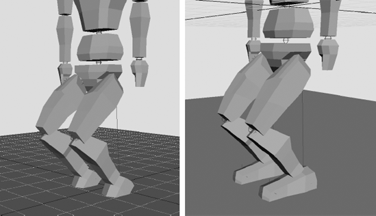
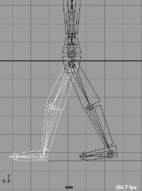
Grab the top joint of the skeleton, which is the pelvis joint. Move the joint, and the entire body moves with it. Select both ankle IK handles, and set a translation key for them (press Shift+W). Grab the pelvis joint again and move it. The feet will stick to their positions on the ground. Move the pelvis down and the legs bend at the knees. Notice how the feet bend into the ground, though (see Figure 9.45 on the left).
Move the pelvis back to the origin. You'll now create an IK handle for the foot so that the foot stays flat on the ground. Open the IK Handle tool. For the start joint, select the ankle; for the end effector, select the joint at the tip of the foot. Repeat for the other foot.
Note
You can invoke the last tool you used by pressing Y.
Set a translate key for the foot IK handles. Move the pelvis down and the legs bend at the knees and the ankle, keeping the feet flush on the ground (see Figure 9.45 on the right).

Because the block man's feet will stick to the ground, creating a walk cycle with IK animation will be far easier than using FK. Making the animation look good is still a tough job that requires a lot of practice.
Load the scene file block_man_IK_v01.mb from the Block_Man project on the CD, or use your own IK-rigged block man with handles at the ankles and feet. The white leg and arm are again on the far side of the character. You'll set keys at every five frames again for the gross animation. To keep this short, we'll just discuss setting poses with the feet. You can always return to the scene to add animation to the upper body with FK, as you did earlier in this chapter.
On frame 1, set translate keys on the pelvis joint and all four IK handles for their start position.
Go to frame 5, and move the pelvis forward about 1 unit. The legs and feet will lift up off the ground a bit and strain to keep their position. Lower the pelvis to get the feet flat on the ground again. Set a key for the pelvis. Because Auto Keyframe is turned on, all keys are set for this animation. (With the FK animation, you set keys for everything at every pose.)
Grab the near IK handles for the ankle and foot, and move them forward and up to match the pose shown in Figure 9.46.
Go to frame 10. Move the front foot forward and plant it on the ground. Move the pelvis another three-fourths of a unit. Set translation keys for the rear ankle and foot handles where they are. Make sure to place the pelvis so that the rear foot is almost flat on the ground. Match the pose shown in Figure 9.47.
Go to frame 15. Move the pelvis another 2 units to center the body over the front foot. Lift the rear ankle and foot IK handles up to bend the knee, and bring the knee up a bit. Match the pose shown in Figure 9.48.
Go to frame 20. Move the pelvis forward 1 unit, and swing the white leg forward as in the pose shown in Figure 9.49.
Move the pelvis three-fourths of a unit forward, and plant the front leg down. Set keys for the rear leg and foot where they stand. Match the pose shown in Figure 9.50.


The next pose should match the pose in frame 10, although with the other leg. Continue the cycle, with each successive pose matching the one 15 frames before it on the opposite side. Don't forget to add FK animation to the top of the body to give your character some weight. Some rotation at the waist and shoulders to make the block man shift his weight as he walks would be a good start.
Many animators use IK chains more often in effects animation than in character work. IK chains can drive whips and ropes, flutter flags, bounce ponytails, and pump pistons as well as move legs and arms. For example, you can use a different type of IK chain, the spline IK chain, to control the shape of your bone chain with a NURBS spline. This is great for snakes and other long, deforming objects.
To create a spline IK chain, choose Skeleton → IK Spline Handle Tool, and then select your top joint and end effector. Maya will create a spline running the length of the bone chain. Adjusting the curvature of the spline will in turn drive the bones, which will in turn drive the geometry bound to them. Figure 9.51 shows a spline curve affecting the curvature of the bones in its spline IK chain.

As you know, Maya is all about the relationships between object nodes. You can create animation on one object based on the animation of another object by setting up a relationship between the objects. The simplest way to do that (outside of grouping) is to create a constraint. For example, you can "glue" one object to another's position or rotation through a constraint.
A constraint creates a direct relationship between the source and the target object's Translate or Rotate attributes. This section explores six types of constraints: point, orient, scale, aim, geometry, and normal.
To attach a source object to a target object but have the source follow only the position of the target, use a point constraint. A point constraint will connect only the Translate attributes of the source to the target. To use this method, select the target object(s) and then Shift+click the source object. In the Animation menu, choose Constrain → Point
The options allow you to set an offset that will create a gap between the source and the target. Constraints are based on the pivots of the objects, so a point constraint will snap the source at its pivot point to the pivot point of the target. Offset would dictate the distance between their pivots in any of the axes.
You can constrain the same source to more than one target object. The source will then take up the average position between the multiple targets. By setting the Weight slider in the option box, you can create more of an influence on the source by any of the targets.
In Figure 9.52, a cone has been point constrained to a sphere. Wherever the sphere goes, the cone follows. This is different from parenting the cone to the sphere in that only its translations are affected by the sphere. If you rotate or scale the sphere, the cone will not rotate or scale with it.
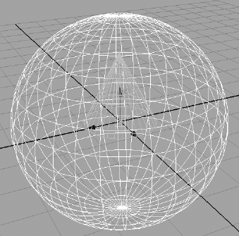
Although you can blend keyframe animation with constraint animation, as a beginner to Maya, consider that once you set a point constraint, you will be unable to control the cone's Translate attributes because they are being driven by the sphere's translations.
Point constraints are perfect to animate a character carrying a cane or a sword, for example. The rotations on the sword are still free to animate, but the sword is attached to the character's belt and will follow the character throughout the scene.
An orient constraint will attach the source's Rotation attributes to the target's Rotation attributes. Select the target object(s) first, and then Shift+click the source object. In the Animation menu, choose Constrain → Orient
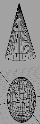
The Offset parameter allows you to set an offset in any axis. Otherwise, the source will assume the exact orientation of the target. In the case of multiple targets, the source will use the average of their orientations. Figure 9.53 shows the cone's orientation following an elongated sphere (the target).

A rotation constraint saves a lot of hassle when you have to animate an object to keep rotating in the same direction as another object. For example, if two speedboats are cruising along neck and neck and one turns, the other could turn to match, keeping them both on course. You could also set offsets and animate them to make the second boat look as if it's reacting to the other so that the animation doesn't look too perfect.
A scale constraint will attach the source's Scale attributes to the target's Scale attributes. Select the target object(s) first, and then Shift+click the source object. In the Animation menu, choose Constrain → Scale
The Offset parameter allows you to set a scale offset in any axis. Otherwise, the source will assume the exact scale of the target. The source will use the average of the scales of multiple targets. Figure 9.54 shows the cone's scale matching the target sphere.
The scale constraint is good for matching the sizes of objects. For example, if an air hose is inflating a string of balloons, constraining the balloons to one target saves you the hassle of animating all their Scale attributes in unison. If a cartoon character's eyes are bugging out at something, you can scale-constrain one to the other so that both bug out in the same time and proportion.
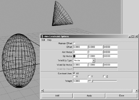
The aim constraint adjusts the source's rotations so that the source always points to the target object. Select the target object(s) first, and then Shift+click the source object. In the Animation menu, choose Constrain → Aim
The aim constraint has more options than the other constraints because you need to specify which axis of the source is to point to the target. You do so using the Aim Vector and Up Vector settings.
The Aim Vector setting specifies which axis of the source is the "front" and will point to the target. In the cone and sphere examples, you would set the Aim Vector of the cone to (0,1,0) to make the Y -axis the "front" so that the cone's point aims at the sphere. If Aim Vector is set to (1,0,0), for example, the cone's side points to the sphere. Figure 9.55 shows the cone pointing to the sphere with an Aim Vector setting of (0,1,0).
The Offset values will create an offset on the source's Rotation attributes, tilting it one way or another. The Up Vector setting specifies which way the cone will face when it's pointing to the sphere.
Aim constraints are perfect for animating cameras to follow a subject, such as a car at a racetrack.
The geometry and normal constraints will constrain the source object to the surface of the target object (as long as it's a NURBS or poly mesh).
With a geometry constraint, the source object attaches at its pivot point to the surface of the target. It will try to keep its own position as best it can, shifting as its target surface changes beneath it. Again, select the target, select the source object, and choose Constrain → Geometry.
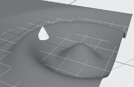
Using a geometry constraint is useful when you want to keep an object on a deforming surface, such as a floating boat on a lake. Figure 9.56 shows the cone after it has been geometry constrained to a NURBS plane that is being deformed by a Wave deformer (choose Create Deformers → Nonlinear → Wave). The cone will sit on the surface as the waves ripple through, but it will not rock back and forth to stay oriented with the surface.
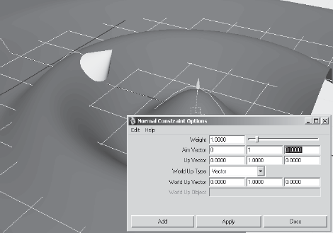
To get the cone to orient itself so that it truly floats on the surface, you need to use a normal constraint. Using a normal constraint rotates the cone to follow the surface's normals, keeping it perpendicular to the surface.
Note
A surface normal is an imaginary perpendicular tangent line that emanates from all surfaces to give the surface direction.
The normal constraint is similar to the aim constraint, and its options are similar. Using the Aim Vector setting, you specify which way is "up" for the object to define the orientation that the source should maintain. This setting will not, however, constrain the location of the source to the target. If you want a floating effect, use geometry and a normal constraint to get the cone to bob up and down and roll back and forth as the waves ripple along (see Figure 9.57).
Three more constraints are possible in Maya: the parent, tangent, and pole vector constraints. A parent constraint constrains an object's translation and rotation to another object by mimicking a parent-child relationship without actually parenting the objects. This keeps objects aligned without worrying about any grouping issues. You will have a firsthand look at this in the exercise where you rig the locomotive later in this chapter. Lucky you!
A tangent constraint keeps an object's orientation so that the object always points along a curve's direction. This constraint is usually used with a geometry constraint or path animation to keep the object traveling along a curve pointed in the right direction, no matter the direction of the curve. Pole vector constraints are used extensively in character animation rigs to keep IK joints from flipping beyond 180 degrees of motion.
A favorite feature for character riggers is the set driven key (SDK). A set driven key establishes a relationship for objects that lets you create controls that drive certain features of a character or an object in a scene.
Before you can use an SDK, you must create extra attributes and attach them to the top node of a character. These new attributes drive part of the character's animation. The term character is used broadly here. For example, you can set up a vehicle so that an SDK turns its wheels.
Let's start with a simple SDK relationship between two objects. You will create a relationship between a ball and a cone. As the ball moves up in the Y -axis, the cone spins in the X -axis. As the ball descends, the cone spins back. You will then revisit the hand and set up an SDK on the skeleton that animates the model.
To create a simple SDK to make a sphere control the animation of a cone's rotation, follow these steps:
Create a NURBS sphere and a cone in a new scene. Move the cone to the side of the sphere, and lay it on its side, as shown in Figure 9.58.
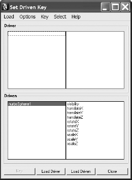
Select the sphere, and in the Animation menu, choose Animate → Set Driven Key → Set. The Set Driven Key window opens with the nurbsSphere1 object selected in the lower half of the window (the Driven section). Its attributes are listed on the right, as you can see in Figure 9.59.
You want the sphere to drive the animation of the cone, so you need to switch the sphere to be the driver and not what's driven. Click the Load Driver button to list the sphere in the top half of the window.
Select the cone, and click the Load Driven button to display the cone's attributes in the bottom half of the window.
In the Driver section, select the sphere's translateY attribute. In the Driven section, select the cone's rotateX attribute. Click the Key button to set an SDK that essentially says that when the sphere is on the ground (Y = 0), the cone's X rotation is 0 because both attributes are currently 0. The cone's rotateX attribute turns orange in the Channel box, meaning a driven key has been set.
Select the sphere and raise it up in Y to a height of 5. Select the cone and rotate it in X to 1800 to make it spin properly. Click the Key button in the Set Driven Key window to specify that when the sphere is at a height of 5, the cone's rotateX attribute will be 1800 degrees. As the sphere's height increases from 0 to 5, the cone spins from 0 to 1800 in X.

Automating some animations on a character is indispensable to an animator. This can't be truer than when setting up an SDK for hand control. After you model and bind a hand to a skeleton, you're ready for an SDK.
Open the scene poly_hand_skeleton_v05.ma from the Poly_Hand_Anim project on the CD, or use your own file that has the hand and its skeleton and is bound (either smooth or rigid) to the skin. Your file should not have animation, though. Set your hand to the bind pose before you begin.
First, you'll create a new attribute called index_pull to control a contracting finger.
Select the hand. (It's best to select the top node handTopNode instead of just the poly mesh of the hand.) In the handTopNode tab of the Attribute Editor, click the Extra Attributes section. For now, at least, this section is empty.
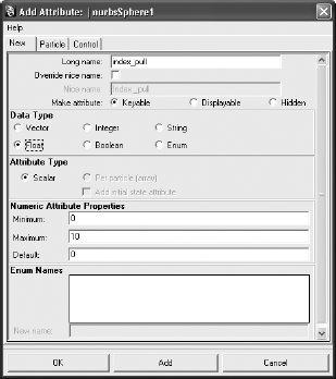
In the Attribute Editor menu, choose Attributes → Add Attributes to open the Add Attribute window, which is shown in Figure 9.60. In the Long Name field, enter index_pull. Make sure that the Make Attribute Keyable check box is checked and that the Float option is selected in the Data Type section. In the Numeric Attribute Properties section, set Minimum to 0, set Maximum to 10, and set Default to 0. Click OK.
After you click OK, the Index_Pull slider appears in the Attribute Editor and the Channel box. This attribute alone will control the entire index finger.
To set up the relationships with the SDK, follow these steps:
With the top hand node selected, open the Set Driven Key window (choose Animate → Set Driven Key → Set). Click Load Driver to specify that the hand should drive the animation.
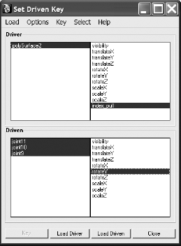
Because you're animating the index finger pulling back, you'll want to drive the rotations of the top three knuckles. Shift+click all three knuckles on the index finger. Click the Load Driven button. All three knuckles will appear on the bottom.
Select the hand's index_pull attribute and the three knuckles' rotateY attributes, as shown in Figure 9.61.
With the rotations of the knuckles at 0 and the index_pull attribute at 0 as well, click the Key button to set the first relationship. When index_pull is at 0, the finger will be extended.
Select the top hand node, and set the index_pull attribute to 5.
Select the fingertip's knuckle (joint11 in the CD file), and rotate it in Y to 20. Select the next joint up the chain (the middle knuckle, joint10), and rotate it to 35 in the Y- axis. Select the final index knuckle (joint9), and rotate it in the Y- axis to 5. Click the Key button. When the index_pull attribute is at 5, the finger will assume this bent position.
Select the top hand node, and set index_pull to 10.
Select each of the three knuckles. Set the tip to rotate to 65 in Y. Set the middle knuckle to 60. Set the last knuckle to 50. Click the Key button to see the result shown in Figure 9.62.
Select the top hand node, and change the value of the index_pull attribute to animate your finger. All you need to do to pull the finger is to set keys on that attribute, without having to rotate the knuckles constantly. Furthermore, you can set up a single SDK to control the bending of all the fingers at once, or you can set up one SDK for each finger for more control.
Open the scene poly_hand_skeleton_v06.ma from the Poly_Hand_Anim project on the CD to see the hand with the SDK setup on the index finger.
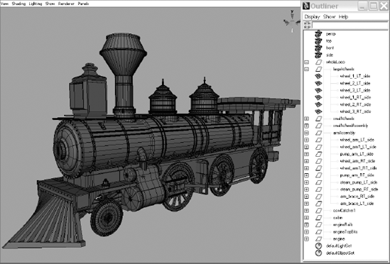
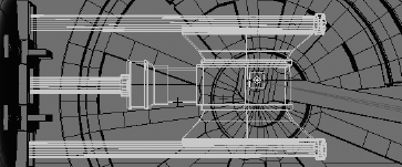
Now let's get back to our locomotive. In the previous chapter, you made sure the hierarchy and pivot placements were proper. In this exercise, you can use your own locomotive scene or the locomotive_anim_v1.mb file from the previous chapter. You can also use a fancy version of the locomotive, called fancy_locomotive_anim_v1.mb; it is set up similarly to locomotive_anim_v1.mb for the exercise. This scene is shown in Figure 9.63.
Familiarize yourself with the scene file first. To give yourself more modeling practice, you can use this scene file to remodel your own fancy locomotive if you like. All the parts of this fancy locomotive were made using the basic tools and procedures laid out in Chapter 4, "Beginning Polygonal Modeling."
Our goal here is to rig the scene to animate all the secondary movements automatically based on some simple controls, such as we did for the hand earlier this chapter. In reality, the locomotive's steam pump drives the arms that then turn the wheels on the locomotive. We will work backward, however, and use one wheel to drive the animation of everything else.
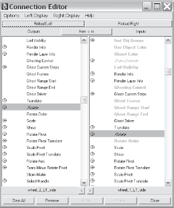
Because all the large wheels have the same diameter, they will rotate the same as the locomotive moves. In this case, we will use the Connection Editor to attach the X Rotation on all the wheels to our main control wheel. We will pick the middle wheel to be the control. To set up the locomotive, follow these steps:
Select the middle wheel on the left side of the locomotive (node wheel_2_LT_side) as shown in Figure 9.64. Open the Connection Editor (choose Window → General Editors → Connection Editor). Click the Reload Left button to load the attributes of the selected middle wheel. Now, select the front wheel on the left side, and click the Reload Right button.
Scroll down in the Connection Editor until you find Rotate in both columns. First, click to highlight Rotate in the left column and then click to highlight Rotate in the right column. This connects the two rotations so that they will both rotate at the same time, effectively letting you drive the animation of both wheels from just the center wheel. Figure 9.65 shows the Connection Editor.
Select the back wheel on the left side (wheel_3_LT_side). Click the Reload Right button in the Connection Editor. Connect the Rotate attribute for the middle and the back wheels. Close the Connection Editor, and select just the middle wheel. When you rotate the wheel, all three wheels rotate together.
Repeat this procedure to connect the rotations of the three wheels on the other side to this middle wheel as well. Now all six wheels rotate in synch with the one control wheel. As a matter of fact, when you select that left-side middle wheel (the control wheel), the other five wheels turn magenta, signifying a connection between these objects.

Note
If you get strange results when you connect the rotations of objects (for example, if the wheels flip over or rotate the opposite direction of the control wheel), try disconnecting all the connections, freezing transforms, and reconnecting the attributes.
We've now automated the animation of the wheels. Next, we will figure out how to connect the wheel arms to the wheels and drive their motion as well. To do so, follow these steps:
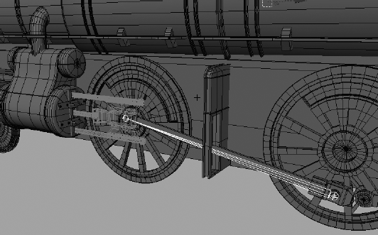
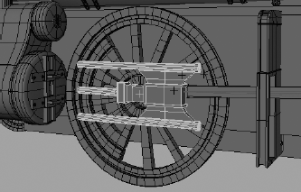
Create a single joint that lines up with the first wheel arm. The root joint will be placed where the wheel arm meets the middle wheel (control wheel), and the end joint will be placed where the wheel arm meets the pump arm, as shown in Figure 9.66. The pump arm has been templated in this graphic (displays in light gray wireframe) to show you the entire wheel arm and joint.
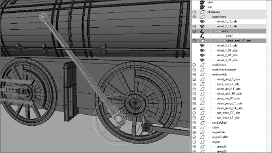
Group the joint under the control wheel's node, as shown in the Outliner in Figure 9.67. Then group the wheel arm under the top joint. This way the joint will rotate with the control wheel, also shown in Figure 9.67, albeit incorrectly to what we need for the pump arm.
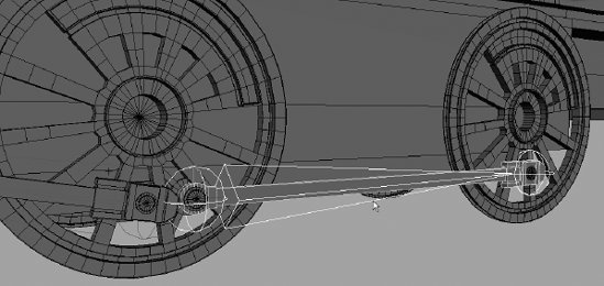
However, as you saw in Figure 9.67, the joint is not rotating properly to make the pump arm work right. The other end of it needs to attach to the pump arm in front of the front wheel, not fly up in space. We'll use an IK handle for this. Make sure the rotation of the control wheel and the joint/wheel arm are set back to 0 to place them in the original position. In the Animation menu, choose Skeleton → IK Handle Tool. Make sure the settings are reset for the tool. Select the root joint as the start joint for the IK Handle. Select the other tip of the bone as the end effector. You now have an IK handle at the tip where the wheel arm connects to the pump arm, as shown in Figure 9.68.
If you rotate the control wheel now, the wheel arm still separates from the pump arm. This is because the IK handle we just created needs a keyframe to keep it in position—that is, attached to the pump arm. Select the IK handle and, at frame 1, set a position keyframe. Now if you rotate the control wheel, the joint and wheel arm will pump back and forth.
Group the IK handle (ikHandle1) under the top node of the locomotive (wholeLoco) as shown in Figure 9.69.

Now we need to attach the pump arm to the wheel arm so that it pumps back and forth as the control wheel turns. If we simply group the pump arm with the end joint of the wheel arm's bone, the pump arm will float up and down as it pumps back and forth. We will need to use a constraint to force the pump arm to move back and forth only in the Z- axis.
Make sure the control wheel is set back to 0 rotation. Select the pump arm, templated in Figure 9.70 so that you can see through to the wheel arm and joint, and line up its pivot with the end joint of the wheel arm bone.
Select the end joint (called joint2), Ctrl+click the pump arm group in the Outliner (called pump_arm_LT_side) and, in the Animation menu, choose Constrain → Point
To fix the pump arm, simply select the vertices on the ends of the cylinders and extend them to make them longer, as shown in Figure 9.72. Now the pump arm will not pull out of the steam pump assembly.
You will have to adjust the pump arm so that the geometry fits when the pump pushes in as well.
The scene file fancy_locomotive_anim_v2.mb will catch you up to this point. Compare it to your work.

Now all that remains is to control the animation of the back wheel and its wheel arm. To set up the wheel arm animation, follow these steps:
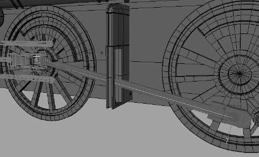
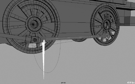
Using the methods described previously (in the steps in the Controlling the Wheel Arms section), create a joint to follow along the wheel arm between the middle control wheel and the back wheel. The root of the joint will be set at the control wheel, as shown in Figure 9.73.
As before, create an IK handle for the end joint of this new bone, where it meets the back wheel, as shown in Figure 9.74. Make sure the handle is at the back wheel, not the middle control wheel.
Group the new joint under the master wheel and then group the wheel arm under this new joint. Now if you rotate the control wheel, the wheel arm rotates with the joint and wheel but does not connect to the back wheel just yet. We need to attach the IK handle we just created for that joint to the back wheel. If you simply group the IK handle, as shown in Figure 9.75, you will run into a problem when you animate. Let's try it: Group the IK handle (ikHandle2) under the end back wheel, as shown in Figure 9.75, and then rotate the control wheel. The wheel arm pumps back and forth along with the back wheel, but every now and then the wheel arm geometry flips over backward. This is not good.
Fixing this is easy. The grouping of the IK handle to the back wheel is causing the issue. Although that is pretty much what we want to do, parenting the IK handle under the wheel is problematic. Here is where the parent constraint becomes extremely helpful. It will give us the desired result without the geometry flipping.
Make sure your control wheel is back to 0 rotation first! MMB+click in the Outliner, and place it outside the hierarchy of the locomotive to remove the IK handle from under the back wheel's node. You may also undo your past actions to the point before you grouped the IK handle (ikHandle2) under the back wheel. You gotta love Undo!
Select the back wheel, Shift+click the IK handle (ikHandle2), and choose Constrain → Parent. Now if you rotate the control wheel, everything will work great.
Group the IK Handle (ikHandle2) under the top node of the locomotive (wholeLoco).

You can use fancy_locomotive_anim_v3.mb to compare your work.
Note
Again, seeing procedures go slightly awry, as when the wheel arm flipped over, is important. Doing so gives you a taste of trouble and a chance to fix it. Troubleshooting is an integral skill for a good CG artist.
We're almost home free with the locomotive wheel rigging. Everything works great when you rotate the control wheel. If you select the top node of the locomotive and translate the train back and forth, everything should work perfectly. Simply repeat the steps in the previous few sections to connect the wheel arms and wheels on the other side of the locomotive and you're done! Figure 9.76 shows the completed and rigged locomotive.

In this chapter, you extended your experience with animation and learned about rigging techniques and automation. Starting with a simple block man, you learned how to set up a hierarchy for Forward Kinematics animation to create a walk cycle. Then you revisited the hand model and used a skeleton to rig the hand for animation. Next, you learned how to bind the geometry of the hand to the skeleton using rigid and smooth binds and how to edit the binding. You also learned how to create an IK system to drive the joints in the block man for an IK walk-cycle animation. After that, you learned how constraints can be used in rigging and how to set up driven keys to create easy controls to animate the hand. Finally, you put all these rigging tricks together to rig the wheels of the locomotive to automate the animation of that complex system with a single control based on the middle wheel.
The true work in animation comes from recognizing what to do in the face of certain challenges and how to approach their solutions. Maya offers a large animation toolset, and the more familiar you become with the tools, the better you'll be able to judge which tools to use in your work. Don't stop with this chapter; experiment with the features not covered here and see what happens.
Animation is about observation and interpretation. The animator's duty is to understand how and why something moves and to translate that into their medium without losing the movement's fidelity, tenacity, or honesty.