
Chapter 10
Autodesk® Maya® Lighting
Light shapes the world by showing us what we see. It creates a sense of depth, it initiates the perception of color, and it allows us to distinguish shape and form. For a scene to be successful in computer graphics (CG), these realities of light need to be reproduced as faithfully as possible. The trick is learning to see light and its astonishing effects on the world around us.
- Learning Outcomes: In this chapter, you will be able to
- Understand basic concepts for setting up CG lighting
- Choose the appropriate Autodesk® Maya® light for a scene based on light attributes
- Control which lights illuminate certain objects through light linking
- Create mood and realism with raytraced shadows
- Illuminate and render a scene with mental ray® Physical Sun and Sky
- Produce special lighting effects with volumetric lighting, lens flare, and shader glow
- Practice setting up a basic lighting solution for the toy airplane, glass candle holder, and decorative box
- Use raytracing to cast shadows in your scene and use refractions to create a glass look
- Animate the attributes of a light and aim lights with the special manipulator
Basic Lighting Concepts
It’s no surprise that lighting in Maya resembles direct-lighting techniques used in photography and filmmaking. Lights of various types are placed around a scene to illuminate the subjects as they would be for a still life or a portrait. Your scene and what’s in it dictate, to some degree at least, which lights you put where.
Although it’s easy to insert and configure lights, it’s how you light that will make or break your scene. Knowing how to do that really comes only with a good deal of experience and experimentation, as well as a good eye and patience.
This chapter will familiarize you with the basic techniques of lighting a scene in Maya and start you on the road to finding out more.
What Your Scene Needs
Ideally, your scene needs areas of highlight and shadow. Overlighting a scene flattens everything and diminishes details. Figure 10-1 shows a still life with too many bright lights.

Figure 10-1: An overlit still life
Similarly, underlighting your scene makes it muddy and lifeless, and it flattens the entire frame. Figure 10-2 shows the still life underlit. The bumps and curves of the mesh are hardly noticeable.
Like a good photographer, you want your image to have the full range of exposure. As in Figure 10-3, light and shadow complement each other and work to show the features of your surface.

Figure 10-2: An underlit still life

Figure 10-3: Balanced lighting creates a more interesting picture.
Three-Point Lighting
The traditional filmmaking and television approach to lighting is called three-point lighting. Three distinct roles are used to light the subject of a shot. More than one light can be used for each of the three roles, but the scene should seem to have only one primary (or key) light, a softer light to fill the scene, and a back light to pop the subject out from the background.
Three-point lighting ensures that the primary subject’s features aren’t just illuminated but featured with highlights and shadow. Using three directions and qualities of light creates the best level of depth. Figure 10-4 shows a schematic of a basic three-point setup.

Figure 10-4: A three-point lighting schematic
Key Light
A key light is placed in front of the subject and off to the side of the camera to provide the principal light on the subject. Because it’s usually off-center, the key light creates one side of brighter light, increasing the depth of the shot. This light also provides the primary shadows and gives the important sense of lighting direction in the shot.
Although it’s possible for several lights to fulfill the role of key light in a scene—for example, three ceiling lights overhead—one light should dominate, creating a definitive direction. Figure 10-5 (left) shows the subject being lit by only a key light, although it’s physically composed of two lights.

Figure 10-5: Key light only
The direction of the two lights remains the same, and one takes intensity precedence over the other and casts shadows. The effect creates a single key light, which produces a moody still life.
- Try This Set your project to the Lighting project downloaded from the book’s website. Open the scene file
still_life_v01.mafrom the Scenes folder.
- Set your project to the Lighting project downloaded from the book’s website. Open the scene file
still_life_v01.mafrom the Scenes folder. - In the camera1 viewport panel, press 7 for lighting mode. It should turn black; there are no lights.
- Click Create ⇒ Lights ⇒ Point Light and, in the persp window, place it as your key light (Figure 10-5, right). Use the camera1 viewport to gauge how the lighting composition is working for optimum placement of the Point light.
Fill Light
A more diffused light than the key light, the fill light seems directionless and evenly spread across the subject’s dark side. This fills the rest of the subject with light and decreases the dark area caused by the key light.
The fill light isn’t usually meant to cast any shadows onto the subject or background itself and is actually used to help soften the shadows created by the key light. Figure 10-6 shows the still life with an added fill light. Notice how it softens the shadows and illuminates the dark areas the key light misses.
Typically, you place the fill light in front of the subject and aim it so that it comes from the opposite side of the key light to target the dark side of the subject. Even though the still life in Figure 10-6 is still a fairly moody composition, much more is visible than with only the key light in the previous figure.

Figure 10-6: A fill light is now included.
- Try This In the existing scene that you started with a single Point light:
- Choose Create ⇒ Lights ⇒ Directional Light. Where you place the light doesn’t matter, but how you rotate it does.
- Rotate the light so you get a lighting direction opposite to the direction of the key light from the Point light already in the scene.
- With the Directional light selected, change its Intensity attribute in the Channel Box or the Attribute Editor from 1.0 to 0.5. Use the camera1 viewport to see how the fill light is working.
Back Light
The back light, or rim light, is placed behind the subject to create a bit of a halo, which helps pop the subject out in the shot. Therefore, the subject has more presence against its background. Figure 10-7 shows how helpful a back light can be.

Figure 10-7: A back light makes the subject pop right out.
The back light brings the fruit in this still life out from the background and adds some highlights to the edges, giving the composition more focus on the fruit.
Don’t confuse the back light with the background light, which is used to light the environment itself.
- Try This In your current scene with the two lights:
- Create a third light to be a Spot light.
- You can use Move and Rotate to position the light to shine from behind the fruit, or you can use the special manipulator. To use that, press T with the Spot light selected. You will see two Move manipulators, one for the source of the light and one for the target.
- Move the target to the front of the column stand and move the target behind and slightly above the fruit (Figure 10-7, right). Use the camera1 viewport to see how the back light should be placed.
Using Three-Point Lighting
The three-point lighting system is used for the primary subject of the scene. Because it’s based on position and angle of the subject to the camera, a new setup is needed when the camera is moved for a different shot in the same scene. Three-point lighting is, therefore, not scene specific but shot specific, as long as it does not break the overall continuity of the scene.
After the lighting is set up for the subject of a shot, the background must be lit. Use a directed primary light source that matches the direction of the key light for the main light, and use a softer fill light to illuminate the rest of the scene and soften the primary shadows.
Maya Lights
Six types of light are available in Maya: Ambient, Directional, Point, Spot, Area, and Volume. These lights are also used when rendering in mental ray. How you use each dictates whether they become key, fill, or rim lights. Each light can fill any of those roles, although some are better for certain jobs than others. The most commonly used light types for most scenes are Spot, Directional, and Ambient. All of these Maya lights render in Maya software as well as mental ray.
To create each light, choose Create ⇒ Lights and click the light type; that light will appear at the origin of your scene.
Common Light Attributes
Lights in Maya are treated like any other object node. They can be transformed, rotated, scaled, duplicated, deleted, and so forth, and they are visible as nodes in the Hypergraph and Outliner alongside other objects in the scene. Like any other node, lights have attributes that govern how they function. Figure 10-8 shows the Attribute Editor for a typical light.

Figure 10-8: A typical light’s Attribute Editor
When you select any light type and then open the Attribute Editor, you’ll see the following attributes and options:
- Type This drop-down menu sets the type of light. You can change from one light type to another (for instance, from Spot to Point) at any time; however, you may not keyframe changing a light’s Type attribute.
- Color This attribute controls the color cast by the light. The darker the color, the dimmer the light will be. You can use Color in conjunction with Intensity to govern brightness, although it’s best to set the brightness of a light to Intensity only. You can keyframe Color easily by simply RMB+clicking the attribute name Color in the Attribute Editor and choosing Set Key. Alternately, you may RMB+click Color in the Channel Box and choose Key Selected from the context menu.
- Intensity This attribute specifies how much light is cast. The higher the intensity, the brighter the illumination will be. You can also keyframe intensity by RMB+clicking the attribute just as with Color.
- Illuminates By Default check box This check box deals with light linking, or the ability to illuminate specific objects with specific lights. Clearing this check box causes the light not to illuminate all objects by default, requiring you to link the light to objects you do want it to light. Keep this check box checked unless you’re linking lights to specific objects. This chapter will briefly touch on light linking later.
- Emit Diffuse and Emit Specular check boxes For all light types except the Ambient light type, these check boxes toggle on or off the ability to cast diffuse lighting or specular highlights on an object (see Figure 10-9). This is useful for creating specific lighting effects. For example, if lighting an object makes it too shiny, you can disable the specular emission from one or more of the lights on that object to reduce the glare.

Figure 10-9: Lights can render diffuse or specular components if needed.
Light Types
Beyond the common light attributes, each light type carries its own attributes that govern its particular settings. In the following section, open the scene file still_life_v01.ma from the Lighting project and create the light being described to see firsthand how that particular light affects the scene.
Ambient Lights
Ambient lights cast an even light across the entire scene. These lights are used for creating a quick, even illumination in a scene; but, as you can see in Figure 10-10, they run the risk of flattening the composition. They’re perhaps best used sparingly and at low intensities as fill lights or background lights, though I personally don’t recommend using them at all.

Figure 10-10: Ambient light
The Ambient Shade slider in the Attribute Editor governs how flat the lighting is. The lower the value, the flatter the lighting. Figure 10-11 shows the effect of two contrasting Ambient Shade settings.
Directional Lights
Directional lights cast a light in a general direction evenly across the scene (see Figure 10-12). These lights are perhaps second to Spot lights as the most commonly used light type. They’re perfect for sunlight or general indoor lighting, for key lights, and for fill and back lights. They give an accurate sense of direction without having to emanate from a specific source.
Point Lights
A Point light casts light from a single specific point in space, similar to a bare lightbulb. Its light is spread evenly from the emission point (see Figure 10-13).
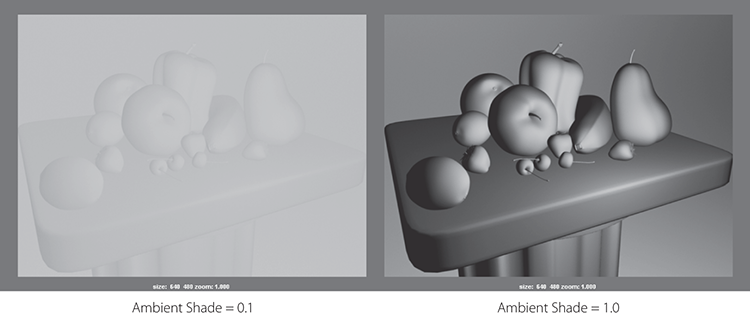
Figure 10-11: A low Ambient Shade setting flattens the image.

Figure 10-12: Directional light

Figure 10-13: A Point light placed in the front right of frame
Using the Decay Rate drop-down menu in the Attribute Editor, you can set how a Point light’s intensity diminishes over distance. With No Decay, the Point light illuminates an object far away as evenly as it does up close. This is the most common setting for most applications.
Setting Decay Rate to Linear, Quadratic, or Cubic requires you to increase the intensity level exponentially to compensate for the decay. You can use Decay Rate settings to illuminate nearby objects and to leave distant ones unaffected. In reality, lights have decay rates, so using them in CG creates a more natural falloff for light, as shown in Figure 10-14.
Point lights are good for effects such as candlelight or setting a mood.
Spot Lights
Spot lights are arguably the most used lights in Maya because they can be used for keys, fills, or rims, and they’re efficient.
Similar to Directional lights, Spot lights emphasize direction. But these lights emit from a specific point and radiate out in a cone shape, whereas Directional lights emit from an infinite source from a certain direction. As such, Spot lights can create a circular focus of light on the geometry much like a flashlight on a wall; Directional lights spread the light evenly. Figure 10-15 shows a Spot light on the still life.

Figure 10-14: A Point light with a Decay Rate set

Figure 10-15: Using a Spot light
The following attributes govern the behavior of Spot lights:
- Decay Rate Specifies the rate at which the light’s intensity falls off with distance, as with the Point light. Again, the intensity needs to increase exponentially to account for any decay.
- Cone Angle Sets the width of the cone of light emitted by the Spot light. The wider a cone, the more calculation intensive it becomes.
- Penumbra Angle Specifies how much the intensity at the edges of the cone and hence the circular focus dissipate. (See Figure 10-16.) A negative value softens the light into the width of the cone, decreasing the size of the focus; a positive value softens away from the cone.
- Dropoff Specifies how much light is decayed along the distance of the cone. The higher the drop-off, the dimmer the light gets farther along the length of the cone. This effect is much better to use than a decay rate, and it gives similar results.
Practical lights are easily created with Spot lights. For example, a desk lamp’s light is best simulated with a Spot light. Remember, with a Spot light, you can press T for the special manipulator, allowing you to move the source and target of the Spot light easily to orient and place the light in your scene.

Figure 10-16: The Penumbra Angle attribute controls the softness of the edge of a Spot light.
Area Lights
Area lights emit light from a flat rectangular shape only (see Figure 10-17). They behave similarly to Point lights, except they emit from an area and not from a single point. You can still set a decay rate, just as you can with Point lights. Area lights are the only lights whose scale affects their intensity. The larger an Area light, the brighter the light.

Figure 10-17: An Area light and its placement
Because you can control the size of the area of light being emitted, these lights are also very good for creating effects such as a sliver of light falling onto an object from a crack in a door (as in Figure 10-18), overhead skylights, or the simulation of large, diffused lighting fixtures such as overhead office lights. Use Area lights when you need to light a specific area of an object.
Additionally, Area lights give off a softer feel the larger they are. Often area lights give the best photographic light quality compared to the other light types, and I personally prefer using them the most, especially when used with mental ray rendering. They create the most accurate-looking shadows, though at the expense of slightly longer render times.

Figure 10-18: An Area light as a sliver and its placement
Volume Lights
Volume lights emit light from a specific 3D volumetric area as opposed to an Area light’s flat rectangle (see Figure 10-19). Proximity is important for a Volume light, as is its scale.
A Volume light can have the following attributes:
- Light Shape A Volume light can be in the shape of a sphere, a box, a cylinder, or a cone. You select a shape from the Light Shape drop-down menu.
- Color Range This section of attributes sets the color of the light using a built-in ramp. The ramp (from right to left) specifies the color from inside to outside. For instance, a white-to-black ramp from right to left creates a white light at the center of the Volume light that grades down to black toward the outer edge.
- Volume Light Dir This attribute sets the direction for the light’s color range: Outward lights from inside out, Inward lights from the volume’s edge into the center, and Down Axis lights as a gradient in an axis of the light.
- Arc And Cone End Radius This attribute defines the shape for the volume.
- Penumbra For cylinder and cone shapes, this attribute adjusts how much the light dims along the edge of its length.

Figure 10-19: A Volume light and placement
Use Volume lights when you need to control the specific area in which light is cast or when you need an object to move into and out of a particular area of light. Volume lights are not to be confused with volumetric lighting, such as the effect of a flashlight in smoke or headlights driving through fog. For volumetric effects, see the section “Volumetric Lighting” later in this chapter.
Lighting a Scene
Any of these aforementioned lights will work with Maya Software rendering and mental ray rendering. It’s also best to start with just a couple types of light, such as Directional and Spot no matter which renderer you use, before turning to the more sophisticated types, such as Area and Volume.
Getting the essence of lighting is far more important in the beginning than understanding the nuances of all the attributes of a light. At first, limit yourself to Spots and Directional lights and try to avoid any Ambient light use.
Light Linking
You can control which lights illuminate which objects by using Maya light linking. However, by default, lights created in your scene illuminate all objects in the scene. The easiest way to create an exclusive lighting relationship is first to create a light and then to turn off the attribute Illuminates By Default in the light’s Attribute Editor. This ensures that this light won’t cast light on any object unless specifically made to do so through light linking.
- Open the scene file
still_life_linking_v01.mafrom the Lighting project or use your own scene that already has at least three lights. Click the Render button ( ) in the Status line to render a frame (Figure 10-20). There are no shadows; you’ll deal with that in the next section.

Figure 10-20: All of the scene’s lights illuminate the scene.
- Create a new Directional light and, in the Attribute Editor, turn off the check box Illuminates By Default (it’s right below the Intensity slider). Set Intensity to 1 or more. You can see the placement of the light in Figure 10-21.
- Render a frame, and you won’t see any change. Adding a new light with Illuminates By Default disabled won’t increase the light level in the scene.
- To assign your new light to the objects you want to illuminate exclusively, choose Windows ⇒ Relationship Editors ⇒ Light Linking ⇒ Light-Centric. This opens the Relationship Editor and sets it for light linking. Light-Centric means the lights are featured in the left side of the panel, as shown in Figure 10-21, and the objects in your scene that will be lit are on the right.

Figure 10-21: The Light Linking window and the newly added Directional light

Figure 10-22: Select the scene objects to link to the Directional light.
- Now, select the light you want to link (in this case, the directionalLight2 you just created) and the objects in the scene you’d like to link to (in this case, the apple and the pepper, as shown in Figure 10-22). Notice that no other objects on the right side of the Relationship Editor are selected; this means they will receive no illumination from this light source.
- Render a frame, and you’ll see that the objects you linked are lit by the new light. In this case, the apple and the pepper are brighter than the other fruit in the still life. (See Figure 10-23.)

Figure 10-23: A linked light creates extra light for only the apple and the pepper behind it. The other objects aren’t illuminated by that light.
When you’re in Lighted mode (press 7 in the viewport) and using the default Viewport 2.0 renderer, linked lights aren’t taken into account in that display. However, if you switch the viewport renderer from Viewport 2.0 to High Quality Rendering (in the viewport’s menu bar, choose Renderer ⇒ Legacy High Quality Viewport), you will be able to see light linking work. Linked lights work with both Maya Software rendering and mental ray rendering.
Adding Shadows
Don’t be too quick to create an abundance of light in your scene to show off your models and textures. Shrouding objects in darkness and shadow is just as important as revealing them in light. A careful balance of light and dark is important for a composition. As Figure 10-24 shows, the realism of a scene is greatly increased with the simple addition of well-placed shadows. Don’t be afraid of the dark. Use it liberally but in balance.

Figure 10-24: Darkness and shadow help add a sense of realism, depth, and mood to an otherwise simple still life.
Creating Shadows in Maya
Lights can cast shadows in one of two ways, depending on how the scene is rendered: depth map shadows and raytraced shadows. Depth map shadows are faster; however, with computing being as fast as it is now, it’s usually just best to use raytraced shadows because they are more accurate and usually look much nicer. You will use raytraced shadows throughout this book.
When you create a light in Maya, raytraced shadows are enabled by default for the light. However, since Maya Software rendering does not have raytracing enabled by default, your renders will not have any shadows at first. You will need to turn on raytracing or switch to mental ray rendering to see your raytraced shadows. You will explore raytracing and mental ray further in Chapter 11, “Autodesk® Maya® Rendering.”
If you do not want to raytrace your shadows for whatever reason, you will need to enable shadow maps for your lights by clicking the Use Depth Map Shadows check box in the Shadows area of the light’s Attribute Editor. Maya will then generate shadow maps that locate where shadows fall by following the path of the light backward from the lighted object to the light itself. Shadow maps are generally fast because they do not need raytracing, but they are not very accurate.
On the other hand, raytracing involves tracing a ray of light from every light source in all directions and tracing the reflection to the camera lens. Therefore, you can create more accurate shadows in your renders.
As you can see, depth map shadows are not as nice as raytraced shadows when you compare Figure 10-25 and Figure 10-26. Raytracing shadows is pretty much the norm now.

Figure 10-25: A light with depth map shadows renders faster, though not as detailed as raytracing.

Figure 10-26: A light with raytraced shadows produces more detailed shadows.
Raytraced Shadows
When you create a light, the light’s Use Ray Trace Shadows setting in the Attribute Editor (see Figure 10-27, toward the bottom of the Attribute Editor window) is turned on by default. If you are rendering with Maya Software, open the Render Settings window by choosing Windows ⇒ Rendering Editors ⇒ Render Settings or by clicking the Render Settings icon (![]() ) in the Status line; then enable the Raytracing check box under the Raytracing Quality heading. Let’s add shadows to the scene using Maya Software rendering first.
) in the Status line; then enable the Raytracing check box under the Raytracing Quality heading. Let’s add shadows to the scene using Maya Software rendering first.
- In the file
still_life_linking_v01.mbfrom the Lighting project, select the Point light. In the Attribute Editor, turn on Use Ray Trace Shadows under the Shadows ⇒ Raytrace Shadow Attributes heading (Figure 10-27, right). In this scene, raytrace shadows have been disabled on purpose. All new lights you create will automatically have raytraced shadows enabled. - Select the Directional light and turn on Use Ray Trace Shadows.
- Open the Render Settings window and enable Raytracing (Figure 10-27, left).
- Render a frame, and you’ll see the scene looks more natural now with shadows (Figure 10-28). Turning on raytracing has also enabled reflections, which you’ll look at later this chapter. Notice how the brighter key light (Point light) casts darker shadows than the darker fill light (Directional). As a general rule, you don’t want too many lights in the scene all casting shadows; that may confuse the composition.

Figure 10-27: Make sure Use Ray Trace Shadows is checked on for the light (right) and enable Raytracing for the Maya Software renderer in the Render Settings window (left).

Figure 10-28: Raytraced shadows add a lot to the scene.
For an object that has a transparency map applied to its shader, however, only raytraced shadows can cast proper shadows. On the left of Figure 10-29 is a plane with a mapped checkerboard transparency casting a raytraced shadow over the still life. On the right is the same light using shadow maps instead of raytraced shadows.

Figure 10-29: Only raytraced shadows work with transparencies.
Controlling Shadows per Object
To better control your lighting, you can specify whether an object can cast and receive shadows in Maya. For example, if you have geometry casting light in front of a shadow but you don’t want it to cast a shadow, you can manually turn off that feature for that object only.
To turn off shadow casting for an object, follow these steps:
- Select the foreground lemon in the
still_life_linking_v01.mascene and open the Attribute Editor. - In the Render Stats section is a group of check boxes that control the render properties of the object, as shown in Figure 10-30 (left). Clear the Casts Shadows check box. If you don’t want the object to receive shadows, clear the Receive Shadows check box.
- Render a frame, and you’ll see the lemon has no shadows on the column’s tabletop; compare the render in Figure 10-30 (right) with Figure 10-28.

Figure 10-30: You easily can set whether an object casts or receives shadows in the Attribute Editor (left). The lemon does not cast a shadow anymore (compare with Figure 10-28).
Raytracing Soft Shadows
One interesting feature of shadows is that they can diffuse or soften as the shadow falls farther away from the object casting the shadow. For example, hold a pen on its end on your desk and notice how the pen’s shadow gets softer or fuzzier the farther it is from where the pen meets the table. This small detail can greatly enhance the reality of any render. To use soft shadows, follow these steps:

Figure 10-31: Regular raytraced shadows
- Open the
still_life_shadows_v01.mbscene from the Lighting project. Check out the render settings. Raytracing is already enabled for the key and fill lights as well as for the renderer. - Render a frame and notice that the shadows are sharp. Save that image into the render buffer by clicking the Keep Image (
 ) icon in the Render View settings. In Figure 10-31, you can see the still life rendered with sharp, raytraced shadows.
 - Select the Point light and open the Attribute Editor. Under the Shadows ⇒ Raytrace Shadow Attributes heading, set Light Radius to 0.2, as shown in Figure 10-32.

Figure 10-32: Setting the Light Radius value
- Select the visible Directional light (not the hidden directionalLight2 in the Outliner) and set its Light Angle option to 4.0. A Directional light’s attribute is called Light Angle instead of Light Radius, but it does the same thing. Now render a frame and compare it to the previous frame you rendered. The shadows are soft but noisy, especially on the background (Figure 10-33). Save your image in the render buffer.
The Directional light had a much higher light radius than the Point light because its shadows react differently. The Point light’s distance from the subject plays a big part in how the light affects the shadows from the subject, so it is more sensitive to Light Radius values than is the non-position-dependent Directional light.
- Now you’ll mitigate the noise. Select the Point light and in the Shadows ⇒ Raytrace Shadow Attributes heading, set Shadow Rays to 16. Select the Directional light and set its Shadow Rays value to 12.
- Render the frame, and your shadows should resemble the ones in Figure 10-34. The higher your Light Radius value, the higher you need to set your Shadow Rays setting to compensate for noise.

Figure 10-33: Soft but noisy shadows

Figure 10-34: A higher Shadow Rays setting makes for cleaner soft shadows.
Notice how the shadows soften more toward the edge of the shadow; the shadow is still sharp at the point of contact. This gives a much nicer feeling of depth to the scene. There is an increase in render time—it’s important to evaluate how much softening you need so you don’t overdo the look or increase the render time too much.
Using soft shadows was easy! Make sure you enable raytracing in Render Settings, of course. These soft raytraced shadows work both in Maya Software rendering and in mental ray rendering.
mental ray Lighting
mental ray lighting and rendering open up a large range of possibilities within Maya. As with all rendering, lighting plays a primary role. I’ll cover mental ray rendering more in the next chapter; however, because rendering and lighting go hand in hand, it’s tough to ignore it in this chapter. This section is a primer on mental ray light functionality.
Two additional functions that mental ray brings to the Maya table are caustics and global illumination (GI). Caustics is the scattering of light reflections off and through semitransparent objects, such as the light that shines on the ceiling above an indoor pool or the sunshine at the bottom of an outdoor pool. Global illumination is the effect of light reflected from one object to another. For example, if you place colored spheres inside a gray box and shine a light into the box, the walls and floor of that box pick up the color of the spheres. The light from the spheres reflects onto the walls and tints them with the spheres’ color. Furthermore, the light from the floor of the box bounces and helps illuminate the undersides of the balls.
For example, Figure 10-35 shows a scene file that has a dozen or so glass spheres inside an enclosed box. The box has four holes in the top, and two Spot lights with shadows turned on are positioned outside the box, shining in through the holes. Figure 10-35 shows a typical Maya Software render. The spheres are visible and reflect the environment, but overall they are dark, with the rest of the box in shadow and no bounced light.
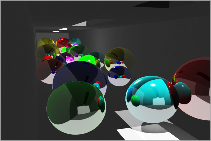
Figure 10-35: The Maya Software render of the box of spheres scene
However, when rendering through mental ray for Maya (see Figure 10-36), the light that enters the box bounces around the scene and illuminates the other spheres. The color of the spheres also colors the area immediately around them because of GI and/or Final Gather (which are lighting methods that allow light to bounce around in the scene giving a greater sense of realism to the render). Additionally, the light shines through the semitransparent spheres and casts caustic highlights on the floor. If you are reading a digital version of this book, you can see the color bouncing around in Figure 10-36.

Figure 10-36: The mental ray for Maya render of the scene
Image-Based Lighting
mental ray also gives you image-based lighting (IBL) in Maya. This method of lighting uses an image, typically a high dynamic range image (HDRI), to illuminate the scene using Final Gather or GI. Final Gather is a form of global illumination that relies on direct as well as indirect illumination. Direct illumination calculates the amount of light coming directly from lights in the scene and renders the result. However, it misses an important aspect of real-life lighting: diffuse reflections of light. Indirect illumination happens when light bounces off objects in a scene in order to reach and therefore light the rest of the scene—that is, diffuse reflections. Final Gather is typically a faster way than GI to get indirect illumination in a scene.
I’ll briefly touch on Final Gather here as you explore Physical Sun and Sky lighting in the next section. However, I’ll cover both IBL and Final Gather in depth in Chapter 11, when you light the toy plane and decorative box model (with displacement maps for box details as well).
mental ray Physical Sun and Sky

Figure 10-37: Enable mental ray rendering in Render Settings.
In Physical Sun and Sky lighting, mental ray for Maya creates nodes in your scene to simulate an open-air sunlight effect for your scene lighting. It’s a quick way to create a nice-looking render. You’ll place the textured red wagon into an open scene and apply a Physical Sun and Sky (PSAS) in the following exercise.
Make sure your project is set to the Lighting project from the web page and use the scene file WagonSunlight_v01.ma from the Scenes folder to follow along with these steps:
- The perspective camera for this scene is already set up in the persp viewport. Open the Render Settings window and switch to mental ray rendering in the Render Using pull-down menu at the top of the window, as shown in Figure 10-37.

Figure 10-38: The mia_physicalsky1 node
- In the Render Settings window, click the Scene tab. Under the Cameras ⇒ Environment heading, click the Create button next to Physical Sun And Sky. The Attribute Editor opens for the mia_physicalsky1 node you just created, as shown in Figure 10-38.
- Render a frame in the Perspective window and compare it to Figure 10-39. It’s a bit bright, but there’s something very nice about this render. Notice that the metal handlebar takes on a good look right off the bat.
The render is too bright, and the wood slats for the railings shouldn’t be reflective. Your render should also show that the fire-engine red of the wagon is a bit washed out.
- Let’s first address the wood railings. Open the Hypershade, and double-click the first Wood shader. Change Reflectivity to 0.1 from 0.5. Repeat for the second Wood shader.
- In the Render View window, click and drag a box region around the wood railings, as shown in Figure 10-40. Click the Render Region button (
 ) to render that part of the frame only.
 - The wood looks much better now, so let’s move on to the brightness of the scene. Open the Render Settings window, and go to the Scene tab. Click the Input arrow next to the Physical Sun And Sky attribute’s button (Figure 10-41). Doing so opens the Attribute Editor for the Physical Sun and Sky.
- Change Multiplier to 0.5 from 1.0, and re-render the frame. The brightness comes down nicely, and the wagon is less blown out than in your previous renders. See Figure 10-42.

Figure 10-39: The first PSAS render doesn’t look too shabby.

Figure 10-40: Render this region to check the reflection in the wood railings.
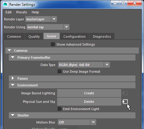
Figure 10-41: Click to open the attributes for the daylight system.
- Let’s play with the direction of the sun. Look in your persp viewport, and you see a Directional light sitting smack in the middle of the scene. Maya uses this light to set the direction of the sunlight, and it doesn’t contribute to the lighting of the scene in any other way. Only its rotation is important to PSAS. Its intensity, color, and other attributes are irrelevant. In this scene, the Directional light is called sunDirection and is in the wagon behind the third texture placement node, as you can see in Figure 10-43. This light represents the sunlight and is currently pointing almost straight down, as if the sun is high in the sky. It seems as if it’s about noon. RotateX for the sunDirection light is –75.

Figure 10-42: Bringing down the brightness of the sun

Figure 10-43: The sunDirection light adjusts only the direction of the sunlight in the scene.
- That third texture placement node is getting in the way. To turn off its display easily, in the persp viewport, click Show ⇒ Texture Placements to uncheck it. The green box disappears in this view until you turn it back on through the Show menu. Now that you can see the Directional light better, you see that the sun is pointed slightly toward the back of the wagon. Rotate the light so that it’s angled away from the camera even more, as shown in Figure 10-44. The sunDirection’s RotateX should be about –25.

Figure 10-44: Angle the sun farther away from the camera.
- Render the frame, and you’ll see quite a difference in the scene. Maya automatically adjusts PSAS settings to make the render appear as if the sun is about to set. This is because of the new angle. The scene (shown in Figure 10-45) not only shows a new lighting direction (the shadows fall toward the back and are longer) but also is a darker and warmer light, as if it were mid-to-late afternoon.

Figure 10-45: Now it’s late afternoon.
- Angle the sunDirection light even more (so RotateX is at about –2.5), almost parallel with the ground plane, and render a frame. Now the sun has all but set, and it’s dark dusk, just before night falls on the scene. See Figure 10-46.

Figure 10-46: It’s getting late; you should get home before nightfall.
- Rotate the sunDirection even more so that it’s at a RotateX of about 15. It’s now dark, and you can barely make out the wagon. (See Figure 10-47.) It’s time to go home before your mom gets mad. Remember, you can adjust the overall brightness of the scene by adjusting the mia_physicalsky1 node attributes, as you did in steps 6 and 7.

Figure 10-47: Ooh, it’s dark—Mom is gonna be mad.

Figure 10-48: The sun also rises!
You can add lights to the scene as well; you aren’t limited to the system’s results. For example, Figure 10-48 shows a render of the wagon with the sun beginning to rise behind it, making the foreground a bit dark. Figure 10-49 shows the same render but with an added Directional light (with an Intensity of just 0.25) pointing toward the front of the wagon. This helps define the front of the wagon, hinting that there is another light source, perhaps a porch light behind the camera.

Figure 10-49: Adding a light to illuminate the front of the wagon in this sunrise scene
The PSAS system can get you some fairly nice results quickly. Keep experimenting with different sunDirection angles as well as the attributes for the system to see what results you can get for your scene. Add lights to create areas of detail in your model.
Unbeknownst to you, when you invoked the PSAS system, Maya turned on Final Gather in the mental ray settings, as well as added a few nodes to the scene including a sky environment that surrounds your scene. This enabled indirect lighting to work in the scene. To get rid of the PSAS, you must go to the Render Settings window, and in the Indirect Lighting tab where you first turned on PSAS, you must click the Delete bar.
You’ll explore Final Gather in the next chapter. At the end of that chapter, though, I’ll introduce HDRI and image-based lighting for a fairly photoreal rendering of the toy plane and decorative box.
This is the perfect time for a break, so save your work (as if I have to tell you that at this point!), go grab some iced tea, and rest your eyes for a bit. In the next section, I’ll go over various special lighting effects before returning to the wagon.
Lighting Effects
In CG, you must fake certain traits of light in the real world. Using certain methods, you can create smoky light beams, glowing lights, and lens flares. Although some of these effects fall under the domain of rendering and shader tricks, they’re best explored in the context of lighting because they’re created by light in the real world.
Volumetric Lighting
How do you create an effect such as a flashlight beam shining through fog? This lighting effect is called volumetric lighting, and you can use it to create some stunning results that can sometimes be time-consuming to render.
You can’t apply volumetric effects to Ambient and Directional light types. To add a volumetric effect to any of the other types of lights, select the light and, in the Attribute Editor under the Light Effects section, click the checkered Map button to the right of the Light Fog attribute. This creates a new render node that appears in the Hypershade window. After you click the Map button, the Attribute Editor takes you to the lightFog node.
Maya handles volumetric lights by attaching a lightFog node to some lights such as a Spot light. The Color and Density attributes under this node control the brightness, thickness, and color of the fog attached to that light. Furthermore, in the light’s Attribute Editor, you can control the fog with the Fog Spread and Fog Intensity settings. Fog Intensity increases the brightness of the fog, and Fog Spread controls how well the fog is defined within its confines. For example, a Spot light with fog shows the fog in its cone. Figure 10-50 shows how Fog Spread affects the conical fog shape. You’ll see that some lights do not have the same fog controls mentioned earlier. The Spot light is perhaps the easiest light with which to create a fog effect.

Figure 10-50: Fog Spread affects how the fog dissipates to the edges of the cone.
If you want the rays of light within the fog to cast shadows, check Use Depth Map Shadows for the light. You’ll have to increase the depth map resolution for a higher-quality image.
Lens Flare
Lens flare and light glow, as illustrated in Figure 10-51, mimic the real-world effect created when light strikes a lens or when the light source is visible in the frame. The flare is created when the light hits the lens at a particular angle and causes a reflection of itself in the optics of the lens.

Figure 10-51: Light glow and lens flare turned on for the back light
To enable a light glow, under the Light Effects section in the light’s Attribute Editor, click the checkered Map button next to the Light Glow attribute to create an OpticalFX node that appears in the Hypershade. The Attribute Editor shifts focus to that new node, which controls the behavior of the light glow and lens flare. The OpticalFX node contains the following attributes and settings:
- Glow Type Setting this attribute specifies the kind of glow: Linear, Exponential, Ball, Lens Flare, and Rim Halo. These define the size and shape of the glow from the light.
- Halo Type Specifying a halo creates a foggy halo around the light in addition to the glow. You can find controls for the halo in the Halo section in the Attribute Editor.
- Star Points Setting this attribute specifies the number of star points the glow generates.
- Rotation Setting this attribute rotates the orientation of the star points.
- Radial Frequency Used in conjunction with the Glow Radial Noise attribute (see the next item) in the Glow Attributes section, this attribute defines the smoothness of any added glow noise.
- Glow Radial Noise Setting this attribute adds noise to the glow effect, creating light and dark patches within the glow for a more random look, as shown in Figure 10-52.
- Glow Color Setting this attribute specifies the color of the glow.
- Glow Intensity and Spread Setting these attributes specifies the brightness and thickness of the glow and how well it fades away.
To turn on a lens flare along with the light glow, click the Lens Flare check box at the upper right in the Attribute Editor for OpticalFX. The attributes in the Lens Flare section control the look of the flare.

Figure 10-52: Glow Radial Noise attribute
Light glows and flares can be highly effective in scenes, adding credibility to the lighting, but they’re often misused or, worse, overused in CG. Used sparingly and with subtlety, lens flares can go a long way toward adding a nice touch to your scene.
Shader Glow Effects
To create a glowing effect, it’s sometimes better to place a glow on a geometry’s shader instead of the light. Because a light must be seen in the shot and pointed at the camera to see any light glow and flare, a shader glow is sometimes more desirable. This process will composite a glow on the object that is assigned the Glow shader to simulate a volumetric light, such as a street lamp on a foggy night. Shader glows have far less render cost than true volumetric lights.
- Try This To light a still-life scene, follow these steps:
- Open the
still_life_v03.mafile in the Lighting project on the web page. Create a Spot light, place it over the still life, and aim it directly down onto the fruit, as shown in Figure 10-53. Turn on Use Depth Map Shadows for the light and set Resolution to 1024. Set Penumbra Angle to 10 and Intensity to 1.5. Press 7 for Lighted mode in the Camera1 viewport to see how the light is being cast. - The Spot light provides the practical light in the scene. You’ll place a bare bulb on a wire directly above the fruit. Create a NURBS sphere, and position it right over the fruit but in the frame for camera1 to see. In the Render Stats section of the Attribute Editor for the sphere, turn off Casts Shadows.
- Create a long, thin cylinder for the lightbulb’s wire and position it as if the bulb were hanging from it, as shown in Figure 10-54. Turn off Casts Shadows for the cylinder as well.
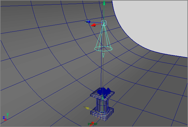
Figure 10-53: Aim a Spot light down toward the fruit.

Figure 10-54: Place a bulb on a wire over the fruit pedestal.
- Create a black Phong E shader to assign to the cylinder.
- Create a Phong shader for the bulb and assign it to the NURBS sphere. Set its Color to a pale, light yellow, and make it about 50 percent transparent.
- Select the Spot light and set its Color to the same yellow. You can do this easily through the Color Chooser. With the shader for the bulb selected, open the Color Chooser by clicking the pale yellow color you just made. Click the right arrow to place the yellow color in the swatches to the right of the main color swatch, or RMB+click any of the swatches.
- Pick the Spot light and click its Color attribute to set the Color Chooser to that color. Click the yellow swatch you created to get the same color on the light. For detail’s sake, make the light’s color less saturated.
- To make the shader glow for the bulb, open the Hypershade and select the bulb’s Phong material. In the Attribute Editor’s Special Effects section, drag the Glow Intensity slider from 0 to 1.0. If you render the frame, you’ll see that the glow isn’t quite enough to make a convincing lightbulb. In the Hypershade, select the shaderGlow1 node; this node controls all the glows in the scene.
- Set Quality to 0.1. In the Glow Attributes section, set Glow Intensity to 6.0, set Glow Spread to 0.5, and set Glow Radial Noise to 0.2.
The scene file still_life_v04.mb from the web page contains the full scene for your reference. See Figure 10-55 for the final result.

Figure 10-55: The bare lightbulb over the still life is created with a shader glow.
Assembling and Lighting a Scene
In this section, you’ll set up and light a simple scene with the toy plane and the decorative box so that you can render them together. Furthermore, in the next chapter, you’ll start using displacement maps for detail on the box, and you’ll use HDRI, mental ray, and Final Gather to get the most from lighting and rendering. The lighting you’ll start with will be basic for now. In the following exercise, you’ll create a basic lighting setup for the scene and get a direct lighting solution first. In the next chapter, you’ll expand on this lighting using mental ray and HDRI.
Set your current project to the Plane project, which you should have already downloaded from the book’s web page. This is important to make sure Maya finds all the project files it needs, so it bears repeating: Set your project to Plane! Did you set your project yet?
How about now?
Assembling the Scene
To begin lighting, open the planeLightingScene_v01.ma scene file from the Scenes folder of the project. This is a simple scene with a camera in place and a corner made up of a redwood tabletop and two white walls:
- Import the assets you need, starting with the toy plane. Select File ⇒ Import and, in the Options section on the right of the Import dialog window, turn off Use Namespaces, set Resolve to Clashing Nodes, and leave With set to the file name. This makes sure that Maya doesn’t append any additional names to original objects being imported from this file. Next choose
planeShading_v01.mafrom the Scenes folder. - Open the Outliner and select the top node of the toy plane (planeGroup). Go into the four-view layout so you can see all four viewports. Select one of the viewports and select Panels ⇒ Perspective ⇒ renderCam. This way you can work in the persp viewport and see how it affects the camera view from which you’ll be rendering.
Next you will bring in the decorative box from the previous chapters. This time, instead of importing, you will use referencing. This allows you to import a file into your current scene. However, with a reference, any time you adjust the original file, it will automatically update that model in the scene it has been referenced in. You’ll see this in action in the next chapter.
- Choose File ⇒ Create Reference. On the right side of the Reference dialog window, check the Use Namespaces box to turn it on. This will place the filename you are referencing in front of the object names in the Outliner.
- Navigate to your Plane project. In the Scenes folder, select
boxDetail01.mbto bring in the latest decorative box scene from Chapter 7, “Autodesk® Maya® Shading and Texturing,” as a reference. This is actually the same scene file asboxTextures03.mbin the Decorative_Box project that you completed in Chapter 7, but cleaned up a bit and placed in the Plane project folders for simplicity’s sake. The texture files you need are also copied into the Plane project’s Sourceimages folder. - Rotate the box to 200 degrees in the Y-axis and position the box next to the toy plane to match Figure 10-56.

Figure 10-56: Orient and place the decorative box next to the plane to match this position.
- You’ll now import the glass candle holder you created in Chapter 5 using NURBS techniques. There’s no need to use a reference like you did with the decorative box, so select File ⇒ Import and turn off Use Namespaces, set Resolve to Clashing Nodes, and leave With set to the filename, just like in step 1.
- Navigate to the candleholder project and, in the Scenes folder, select and import the
candleModel_v03.mbfile. - In the Outliner, select the candle’s top node (candleGroup) and move it to the front side of the toy plane, near to the camera. You will also have to scale the candleGroup to 0.65 to match the position and size in Figure 10-57. Don’t worry, the candle holder is all gray for now. Save!

Figure 10-57: Import and place the candle to match this layout.
Creating the Lights
Save your file and compare it to planeLightingScene_v02.ma or skip to the following section. Here you will lay out lighting using the three-point lighting system discussed earlier.
- In the renderCam viewport, press 6 for Texture mode and then 7 for lighted display mode. Using the persp viewport, create a Spot light; in the Attribute Editor, set Cone Angle to 70.0 and Penumbra Angle to 10.0. Place and orient the Spot light to be the key light, matching the position and orientation shown in Figure 10-58.
- Create a Directional light and place that as shown in Figure 10-59. Set Intensity to 0.6.
- Create a rim light with a Spot light with an Intensity value set to 0.7; place it as shown in Figure 10-60. Set Penumbra Angle to 10.0. Try using the special manipulator for the Spot light by pressing T. This way you can place the source and the target of the light to more easily position it.

Figure 10-58: Create a Spot light and place it as shown.

Figure 10-59: Create and place a Directional light as shown here.

Figure 10-60: Create a Spot light for a rim light and place it as shown here.
- In the renderCam viewport, render a frame (by clicking the icon in the Status line); you should see something like what is shown in Figure 10-61. You need to create a simple glass shader for the candle, and there are no shadows or reflections yet, but it’s a start. You’ll enable raytracing in the next section to make a glass shader and render shadows.
Reflection and Shadows
Save your file and compare it to planeLightingScene_v03.ma or skip to the following section. Here you will make rendering reflections and shadows possible.
- Open the Render Settings window (
 ) and click the Maya Software tab. In the Raytracing Quality section, click to enable Raytracing. If you render your scene now, you’ll notice shadows in the image; however, the rim light has disappeared. That is because it is behind the back wall and is being blocked. You need to turn off shadows for that rim light in the next step.

Figure 10-61: A simple render of the plane
- Select the Spot light that is your rim light (behind the back wall). In the Attribute Editor, under Shadows ⇒ Raytrace Shadow Attributes, uncheck the Use Ray Trace Shadows box to turn off those shadows.
- If you render the frame now, it should resemble the image in Figure 10-62. It’s a basic look, but it’s getting nicer now that you see reflections in the objects (except the candle holder) and shadows.
- Now let’s soften the shadows. Select the first Spot light you created (the key light) and, in the Shadows ⇒ Raytrace Shadow Attributes section, set Light Radius to 9.0 and Shadow Rays to 12.

Figure 10-62: Render with the rim light shadows turned off.
- Render a frame, and the shadows look nicer and more real. You can experiment with the light’s Light Radius and Shadow Rays values to dial in the shadows to your liking. The sharper the shadow, the smaller and the closer the source of the light will appear.
- However, the reflections in the toy plane make the plastic look too shiny. Select the body of the plane in the persp viewport and open the Hypershade window. In the Hypershade, click the Graph Materials On Selected Objects icon (
 ) to bring up the plane’s yellow Blinn shader in the Work Area.
 - Click the yellow shader and, in the Property Editor, under the Specular Shading section, set Eccentricity to 0.425, Specular Roll Off to 0.525, and Reflectivity to 0.25.
- Select the gray Blinn shader and repeat the same attribute values as step 7.
- In the Hypershade, click the phongFloor shader and set its Cosine Power to 30 and Reflectivity to 0.15. Render, and your frame should look more like Figure 10-63.
You can see that simple additions of shadow and reflections helped this render look nicer.

Figure 10-63: Reducing the glossy look of the plastic toy plane and the wooden tabletop
Making Glass
Now turn your attention to the glass candle holder and the candle inside. You can continue with your own scene or load the scene file planeLightingScene_v04.ma to skip to this point. You will create a glass shader and a simple shader for the candle in the following steps:
- In the Hypershade, create a new Phong shader and name it candleGlass.
- Open the Outliner. Shift+click the plus sign to the left of the candleGroup node to expand all the child nodes beneath it. Select the glassJar and glassLid objects; in the Hypershade, RMB+click the new candleGlass Phong shader and choose Assign Material To Selection.
- In the candleGlass shader, move the Transparency slider so that the black color swatch turns almost pure white. This will make the shader almost entirely transparent.
- Set Cosine Power to 60 to make the specular highlights tighter and more glossy looking. Render a frame, and you’ll notice the jar is now clear glass with a gray candle inside. You may also notice some strange vertical bars between the glass and the gray candle (Figure 10-64).
This phenomenon occurs when two surfaces penetrate each other. Since Maya is interpreting the geometry of the glass and the candle inside slightly differently during render time, this penetration may occur. You can simply reduce the size of the candle inside ever so slightly. However, you will address this issue when you render this scene with mental ray in the next chapter, so you can leave it be for now.
- There is a gray ring inside the lid of the jar that should be white plastic. In the Hypershade, create a new Blinn and give it a white color. Set Reflectivity to 0.1. Call this shader whitePlastic.
- In the Outliner, select the plasticSealer object under the jarLid group and assign it to the whitePlastic shader.
- Make another Blinn shader and give it a dark red color. Set Eccentricity to 0.125, Specular Roll Off to 0.85, and Reflectivity to 0.1. Name it candleWax.

Figure 10-64: Rendering a glass look for the candle jar shows a little bit of penetration with the gray candle inside. That’s okay for now.
- In the Outliner, select the candle object grouped under the jarCandle group and assign it to the candleWax shader.
- Finally, create a dark gray Lambert called blackWick and assign it to the wick object in the Outliner.
- Render your scene and have a look. The candle is looking nicer, but the glass is missing something still. You need to create refractions in the glass of the candle holder.
- Select the candleGlass Shader and, in the Property Editor, scroll down to and open the Ray Tracing section. Check the Refractions box to turn on refractions and set Refractive Index to 1.1. For refractions to show up, you will need to have a Refraction Index value other than 1. The lower or the higher than 1.0 that you set this value, the more distorted the refraction will be. Small deviations from 1.0 give you the best results; going too high or too low may look super weird.
- Before you render, go to the Render View window first (if you closed Render View after your last render, choose Windows ⇒ Rendering Editors ⇒ Render View). Click and drag a box around the candle in the image of your last render and then click the Render Region icon () to just render that part of the frame to save time. Your glass render should look much more like glass now (Figure 10-65).
The render is not looking too shabby, but when you tackle this scene again with mental ray in the next chapter, you will see how powerful mental ray rendering can be. In Chapter 11, you’ll add more texture maps to add carving detail to the decorative box, create mental ray specific shaders for the objects in the scene, and enable Final Gather to use an HDR image to light the scene to take it to a new level. Woo!
You can check your work against the scene file planeLightingScene_v05.ma in the Scenes folder of the Plane project.

Figure 10-65: The glass looks much nicer with refractions enabled.
Further Lighting Practice
Lighting professionals in the CG field are called on to find the most efficient way to light a scene and bring it to the peak of its beauty. Again, this comes only from experience. The best way to become a crackerjack lighting artist is to spend years honing your eye and practicing the latest procedures, such as HDR lighting.
The file still_life_v01.ma in the Lighting project on the web page contains the scene of the still life with no lights, so you can play with lighting and shadow methods as well as light linking to create some extra focus on some parts of the frame. The file still_life_v02.mb contains the same scene but with three-point lighting already set up.
Notice in the still_life_v02.ma file that two lights make up the key light (spotLight1 and spotLight2). One light makes up the fill light (directionalLight1), and two lights (spotLight3 and spotLight4) make up the back light.
For practice, download some models from the Internet and arrange them into your own still-life scenes to gain more lighting experience. Set up scenes, time the rendering process, and try to achieve the same lighting look using faster lighting setups that may not be as taxing on the renderer. Also, try taking pictures of situations and trying to match the lighting in the photo.
Try setting up simple scenes. Start with an indoor location that is lit by a single lightbulb. Then, try the same scene in the following locations to expand your lighting repertoire:
- A photography studio
- Outside in the morning on a bright summer day
- Outside at dusk in the fall
- Outside at night under a street lamp
- Inside on a window ledge
- At the bottom of a closet lit by a nearby hallway light
Tips for Using and Animating Lights
When you’re lighting a scene, invoking a lighting mode in your perspective or camera viewport will give you great feedback regarding the relative brightness and direction of your lights. Most consumer graphics cards can handle a maximum of eight lights in Lighted mode; some professional cards can handle more.
As you’ve seen, you invoke Lighted mode by pressing 7 on your keyboard (not through the number pad on the side). You must first be in Shaded mode (press 5) or Texture mode (press 6) to be able to press 7 for Lighted mode. Remember that Lighted mode displays linked lights as if they’re lighting the entire scene. This can cause some confusion, so it’s wise to take notes on any light linking in your scene.
The Maya IPR renderer is also useful when lighting a scene. This almost-real-time updating renderer will give you a high-quality render of your scene as you adjust your lights. Chapter 11 will explore the IPR renderer.
Animating a Light
Any attribute of a light can be animated in the same way that you animate any other object attribute. You can’t, however, animate a light’s type. To edit a light’s animation, you need only select the light and open the Graph Editor to access its keyframes. You can set keyframes on Intensity, Penumbra Angle, Color, and so on, within the Channel Box or the Attribute Editor. RMB+click the name of the attribute and choose Key Selected from the context menu.

Figure 10-66: Set a key for the light.
When you animate the color of a light or a shader, you set keyframes for the color’s RGB values as three separate keyframes. The Graph Editor shows a separate curve for the red, green, and blue channels of color when you animate a light’s color. You can set all three keys at once by RMB+clicking the Color attribute in the Attribute Editor and choosing Set Key from the context menu, as shown in Figure 10-66.
In addition, lights can be animated to be moved, scaled, and rotated like any other object. For further study, try animating the lighting for the simple scenes you set up to practice lighting from the previous section. Try creating animated lights to simulate a candle illuminating your scene, a campfire, or the flashing emergency lights you would find in your average space-station airlock.
Using the Show Manipulator Tool for Lights
As you saw earlier in the chapter, an easy way to manipulate lights is to use their special manipulator. For example, pressing T or choosing Modify ⇒ Transformation Tools ⇒ Show Manipulator tool with a Spot light selected gives you two Translate manipulators in the viewport, as shown in Figure 10-67, and displays the icon (![]() ) below the Tool Box.
) below the Tool Box.
This allows you to move the source or target of the light to aim it better. By clicking the cyan circle that appears below the source’s Translate manipulator, you can toggle through a number of manipulators to adjust the Spot light’s settings, such as cone angle (two clicks clockwise) and penumbra angle (three clicks clockwise). Figure 10-68 shows the manipulator for cone angle.

Figure 10-67: Using special manipulators to place and orient the Spot light

Figure 10-68: Adjusting the cone angle interactively with the special manipulator
Source and Target Translate manipulators are available for all light types through the Show Manipulator tool as well.
Summary
This chapter explored lighting in Maya, beginning with basic concepts that included the three-point lighting technique. You then learned about the different lights in Maya, how they work, and how you can use light linking to control your scene better. Shadows are an important part of lighting and were covered in this chapter, followed by a quick exploration of the Physical Sun and Sky system with mental ray and then lighting effects such as lens flare and light glows. You then created simple lighting for the toy plane, candle holder, and decorative box for a still rendering. You used raytracing to enable reflections and shadows as well as to create a glass look with refractions. Finally, you learned how to begin animating lights for your scenes.
Lighting is truly the linchpin of CG; it can make or break a scene. As you’ll see in the next chapter, lighting goes hand in hand with rendering and shading, and the more you understand about all three functions, the better your scenes will look. Don’t be afraid to experiment with lighting and shading schemes on all your projects.