
Chapter 9
More Animation!
Now that you have a little more animation experience, you can get into some more involved animation practices and toolsets, exploring the principles covered in this book and its examples. Animation is a long journey, and you should use this book as a stepping-off point. For everything you’re being exposed to here, there are many more techniques to discover.
- Learning Outcomes: In this chapter, you will be able to
- Use hierarchies in animation tasks
- Create and manipulate a skeleton system for animation and group models to bones
- Create a walk cycle using forward kinematics for pose animation
- Discern the two ways—smooth and interactive—to bind a mesh to a skeleton in Maya
- Use inverse kinematics in a rig of a simple character
- Create a walk cycle using IK animation
- Use constraints to automate animation
- Create set-driven keys for animation rigging
- Rig a locomotive for automated animation
- Rig a simple character for basic character animation
Skeletons and Kinematics
In your body, your muscles move the bones of your skeleton, and as your bones move, parts of your body move. In computer graphics (CG) animation, a skeleton is an armature built into a 3D model that drives the geometry when the bones are moved. You insert a skeleton into a CG model and attach or bind it to the geometry. The skeleton’s bones are animated, which in turn move the parts of the geometry to which they’re attached. By using a skeleton, the Autodesk® Maya® software allows you to bend and deform the attached geometry at the skeleton’s joints. A skeleton is useful for character work, but skeletons have many other uses. Any time you need to drive the geometry of a model with an internal system, such as a fly-fishing line or a tree bending in the wind, you can use skeletons. You’ll use skeletons to drive locomotive wheels and a simple character later in this chapter.
Skeletons and Hierarchy
Skeletons rely on hierarchies (see Figure 9-1). Bones are created in a hierarchical manner, resulting in a root joint that is the parent of all the joints beneath it in the hierarchy. For example, a hip joint can be the root joint of a leg skeleton system in which the knee joint is the leg’s child, the ankle joint belongs to the knee, and the five toe joints are the ankle’s children.
Geometry need not deform to be attached to a bone system; objects can be grouped with or under joints. They move under their parent joint and rotate around that joint’s pivot as opposed to their own pivot point.
A skeleton is really just a collection of grouped and properly positioned pivot points called joints that you use to move your geometry. A bone is the length between each joint; bones show you only the skeletal system and are not actual geometry.
Inverse kinematics (IK) and forward kinematics (FK) are the methods you use to animate a skeletal system. FK rotates the bones directly at their top joint to assume poses. This method resembles stop-motion animation, in which you pose a puppet, along with its underlying armature, frame by frame. With FK, the animator moves the character into position by rotating the joints that run the geometry.
Rotating a joint affects the position of the bones and joints beneath it in the hierarchy (see Figure 9-2). If you rotate the hip up, the knee and ankle swing up as if the character is kicking.
IK uses a more complex, but often easier, system of IK handles that are attached to the tip of a joint system. The corresponding base of the IK system is attached farther up the skeleton hierarchy to a joint determined as the root of that IK segment. It need not be the root joint of the entire skeleton, though.

Figure 9-1: A leg skeleton and its hierarchy

Figure 9-2: In forward kinematics, the joints are rotated directly.
The bones and joints in the IK chain are affected only by movement of the IK handle. When the handle moves, an IK solver figures out how to rotate all the joints to accommodate the new position of the IK handle.
The effect is as if someone grabbed your hand and moved it. The person holding your hand is similar to an IK handle. Moving your hand causes the bones in your arm to rotate around the shoulder, elbow, and wrist. As you can see in Figure 9-3, the animation flows up the hierarchy and is therefore called inverse kinematics.

Figure 9-3: In inverse kinematics, the joints rotate in response to the IK handle’s position.
Forward Kinematics: The Block Man
To understand skeletal hierarchy, look at Figure 9-4, which shows a simple biped (two-legged) character made of primitive blocks. He’s called the Block Man. (Clever!) Each block represents part of the body, with gaps between the blocks representing points where the body pivots.

Figure 9-4: The Block Man’s cubes arranged
The pivot of each block is placed to represent the appropriate joint location. For example, the shin’s pivot is located at the knee. Each block is grouped up the chain so that the foot moves with the shin, which moves with the thigh, which moves with the pelvis.
The hands are grouped under the arms, which are grouped under the shoulders, and so forth, down the spine to the pelvis. The head groups under the first neck block and so on down the spine to the pelvis. The pelvis is the center of the body, which is known as the root of the figure.
The way this figure is grouped (see Figure 9-5) represents how the hierarchy of a character works for the most part. Each body part is attached and becomes the child of the part above it in the chain.
Load the file block_man_v02.ma from the Block_Man project folder on the book’s web page, www.sybex.com/go/introducingmaya2016, for a good reference of the grouping structure. This file shows you what a skeleton hierarchy does.
In the Hypergraph Hierarchy window, choose Options ⇒ Layout ⇒ Freeform Layout to position the nodes any way you want. To make selections easier, you can arrange the nodes as if they were on a body (see Figure 9-6). You can toggle between freeform and automatic, and your freeform layout will be retained.

Figure 9-5: Pivot placements and grouping

Figure 9-6: A freeform layout in the Hypergraph Hierarchy window
Creating the Skeleton
The basis of how the Block Man is laid out and grouped is what skeletons are all about. Skeletons make character animation easier by automating, at the least, the hierarchy and pivot placement described earlier.
You’ll use the Block Man to create a simple skeleton. Load block_man_v01.ma from the Block_Man project. This is the same as block_man_v02.ma, but this version isn’t grouped.
- Maximize the front view window. Switch to the Rigging menu set by using the drop-down menu or by pressing F3.
- Activate the Joint tool by choosing Skeleton ⇒ Create Joints. Your cursor turns into a cross.
- Click in the middle of the pelvis to place the first joint, which is the root joint of the skeleton.
- Shift+click up to the space between the pelvis and the waist.
By pressing Shift as you click, you create a joint in a straight line from the last joint placement. A bone is created between the two joints as a visual guide to the skeleton. The placement of the joints depends on the active view.
- Click more joints up the spine at the gaps between the body parts, as shown in Figure 9-7. Place the second-to-last joint at the base of the skull, as shown in the side view in Figure 9-7. Place the last joint at the top of the head. Then press Enter to exit Create Joints. Select the top joint at the head and, in a side view, move that joint toward the forehead as shown to make the angle in Figure 9-7.

Figure 9-7: Place spine joints straight up the middle of the body and offset the last joint in the head.
- Use Figure 9-7 as a guide to name all your joints. Now you need to start a new branch of joints leading into the legs and arms. Begin with the arms.
- Activate Create Joints (Skeleton ⇒ Create Joints). In the front view, click to place a new joint at the top-left side of the upper chest just to the side of the joints you’ve already placed (see Figure 9-8, left); then click to place a second connected joint in the bicep at the shoulder. Click down to create joints at the elbow, the wrist, and the tip of the character’s right hand (which is on the left side of your screen). Press Enter to complete that part of the skeleton.
- Reenter Create Joints and repeat the previous step to create joints for the other arm, as shown in Figure 9-8 (right). Name your joints!
- You’ll notice that the arms are not part of the main skeleton yet. You need to connect them to the main skeleton. Open the Outliner and select the lt_clavicle joint. MMB+drag it to the chest node to group it to the chest (see Figure 9-9). Notice that a new bone appears between these two joints. Group the rt_clavicle to the chest as well. Figure 9-10 shows the arms are now part of the main skeleton.

Figure 9-8: Place joints for the arm.

Figure 9-9: Group the lt_clavicle to the chest.

Figure 9-10: The arms are grouped to the chest, and the joints are connected with new bones.

Figure 9-11: Place the leg joints and name them.
- To start another string of joints in the first leg, enter Create Joints. Then click the pelvis joint, selecting it. In the front view, place the first leg joint at the top of the screen-left thigh (the character’s right thigh). Place the next joint between the thigh and knee and then another at the top of the foot where it meets the ankle. Do not exit Create Joints yet!
- Switch to the side view and place another joint at the ankle, another in the middle bottom of the foot, and the last joint at the tip of the foot. Press Enter to exit Create Joints, and you’ll see that your leg is already attached to the pelvis; there’s no need to group in the Outliner this time like with the clavicles.
- In the side view, select the knee joint, and enter Pivot mode by pressing and holding the D key. Very slightly move the knee joint away from the front of the character, out toward the toe. This slight bend will be needed later when you continue the character rig. Using Pivot mode, make sure your joints are placed properly for the leg and foot using Figure 9-11 as a guide. Name your joints!
- Select the rt_hip joint and press Ctrl+D to duplicate the hip and the joints beneath it. In the front view, move the new rt_hip1 joint to the other leg and place it as shown in Figure 9-12 (left). Rename those new joints as shown.
You’re all done! You’ll be adding to this later in the chapter as you create a more well-rounded rig for the character, but for now, check your work against Figure 9-12 (right) and the block_man_skeleton_v01.ma file from the Block_Man project.

Figure 9-12: Duplicate the leg joints, move them to the other leg, and name the new joints (left). The skeleton is complete (right).
Attaching to the Skeleton
You now have a full skeleton for your character. To attach the geometry, all you need to do is parent the body parts under their appropriate joints. Before you get to that, take a few minutes and make sure all your joints are named in the Outliner to make the scene easier to manage. You can use Figure 9-13 as a naming reference.

Figure 9-13: After you check your naming, you’ll parent the pelvis geometry under the pelvis joint.
You can also load the block_man_skeleton_v01.ma file from the Block_Man project to get to this point.
To parent the Block Man’s geometry to the skeleton, follow these steps:
- Starting with the pelvis, parent it under the pelvis joint by MMB+clicking and dragging it to the pelvis joint. Once it’s in the group, MMB+drag the pelvis_geom again and place it between the pelvis and waist joints, as shown in Figure 9-13.
- Continue the MMB+dragging process in the Outliner to place everything but the feet geometry in its proper place in the skeleton using the following list and Figure 9-14 as guides. You will deal with the feet a little differently. Figure 9-14 shows the finished hierarchy in the Outliner and Hypergraph.
- Shins under the knees; thighs under the hips
- Hands under the wrists; forearms under the elbows
- Biceps under the shoulder joints
- Head under the head joint (not the head_tip joint)
- Top neck geometry (neck_2) under neck_2 joint
- Bottom neck geometry (neck_1) under the neck_1 joint
- Chest under the chest joint
- Belly under the belly joint
- Waist under the waist joint
- Now you’ll bind the feet to the foot joints, instead of grouping them. Since there is a joint in the middle of the foot, you’ll want to bend the foot. You will explore binding in more detail later in the chapter, but for now, select the l_foot geometry in the Outliner; then press Ctrl and select all three foot joints (lt_ankle, lt_ballFoot, and lt_foot) in the Outliner as well (see Figure 9-15, left).
- Select Skin ⇒ Bind Skin ❏, set Bind To to Selected Joints and Bind Method to Heat Map, and click the Bind Skin button. This will bind (a.k.a. skin) the foot geometry to the joints so you can then bend, or deform, the foot.
- To test the bind, select the middle foot joint (lt_ballFoot) and rotate it; the tip of the foot should move. Select the ankle and rotate it, and the whole foot should move. Undo your rotations or set the rotations back to 0 so that the foot is at its rest pose (a.k.a. bind pose) again. Just don’t undo the binding unless you need to redo steps 3 and 4. (See Figure 9-15, right.)
- Repeat steps 3 and 4 for the other foot to bind the geometry and test its movement. Just remember to undo your rotations to return to the bind pose.
The Block Man is now set up with a skeleton that you’ll use to make a simple walk cycle. This exercise will help get you more familiar and comfortable with animating a character. You will do more to this setup to make a better animation rig for the Block Man character later in the chapter.

Figure 9-14: Parent all the geometry except the feet into its proper place in the skeleton. The finished hierarchy is shown in the Hypergraph and Outliner side-by-side.

Figure 9-15: Bind Skin Options: the left foot geometry and the left foot joints selected (top). Bind and test the left foot (bottom).
The Block Man: FK Walk Cycle
A walk cycle is an animation that takes the character through a few steps that can be repeated many times so that the character seems to be taking numerous steps. In a cycle, make sure the position of the first frame matches the position of the last frame so that when the animation sequence is cycled, no “pop” occurs in the motion at that point.
Now, try animating this character’s walk cycle using FK on the skeleton. You’ll find the workflow straightforward, as if you were adjusting positions on a doll.
Load the block_man_skeleton_v02.ma file from the Block_Man project from the companion web page for the properly grouped and bound model and skeleton. In this file, the right arm and leg have drawing overrides enabled; this makes their wireframe display white to make it easier to distinguish between the right and left sides while working.
Use the key poses in the following figures to guide you in animating the body as it walks. You’ll key at five-frame intervals to lay down the gross animation. You can go back and adjust the timing of the joint rotations in the Graph Editor to make the animation better later. The white leg and arm are behind the body, farther from the camera.
This type of animation is also called pose animation because you’re posing the character from keyframe to keyframe.
Starting Out: Frames 1 and 5
Figure 9-16 shows the character’s starting position. Here, you’ll set a key for this position and then begin the walk cycle by moving the joints into their second position and keyframing that.

Figure 9-16: The character’s starting position
- At frame 1, set a key for the rotation of all the joints. The easiest way is to select all the joints (and only the joints) in the Outliner or the Hypergraph. With pose animation, you have to make sure that all the joints are keyframed at every step, even if Auto Keyframe is turned on. Also set a position keyframe for just the pelvis joint.
- Go to frame 5. Rotate the back leg back (the Block Man’s right, white leg), rotate the rt_ballFoot joint to bend the foot, and bend the ankle to make the ball of the foot level again. Lower the body (select and move the pelvis joint) to line up the back heel with the ground. This will keep the man on the ground as he goes through the walk cycle, although he won’t actually move forward yet.
- Rotate the near leg (the man’s left blue wireframe leg) forward, bend the knee, and pivot the foot up a bit.
- Rotate the back white wireframe arm forward and rotate the near arm back (opposite from the legs). Bend the arms at the elbows.
- Bend the man forward at the waist, bend neck_1 forward, and tilt the head back up to compensate a little. Figure 9-17 shows the pose at this point.
- Select all the joints in the Outliner and set a rotation key. You’re setting a pose for all the joints, which will ensure that all the body parts are in sync.
If you don’t key everything every step of the way, some parts of the body won’t key with Auto Keyframe properly because the last time they moved may have been two steps previous. This may cause confusion, so it’s best to key every joint at every step until you feel more comfortable editing character animation.

Figure 9-17: The second pose (frame 5)
Frame 10
Figure 9-18 shows the position you’ll keyframe at frame 10; it’s approximately midstride for the first leg.

Figure 9-18: The third pose (frame 10)
- Go to frame 10. Rotate the back leg out further and level the foot. Lower the body to place the man on the ground.
- Rotate the front leg out, straighten the knee, and flatten the foot to place it on the ground. This is midstride. Swing the arms in their current direction a touch more. Bend the torso forward some more. Make sure you set a key for all the joints.
Frame 15
Figure 9-19 shows the position you’ll keyframe at frame 15. At this point, the character begins to shift his weight to the front leg as it plants on the ground, and the character also begins lifting the back leg.

Figure 9-19: The fourth pose (frame 15)
- Go to frame 15. Rotate the front leg back toward the body and raise the body as the man steps to keep the front foot flat on the ground. Rotate the back knee up to lift the foot and rotate the foot down to make him push off the toe.
- Start swinging the arms in the opposite direction. Start straightening the torso back up, but bend the head forward a bit.
Frame 20
At frame 20, the man will shift all his weight onto the front leg and move his body over that leg, lifting his rear leg to begin its swing out front to finish the stride. Figure 9-20 shows the pose.

Figure 9-20: The fifth pose (frame 20)
Follow these steps:
- Rotate the front leg almost straight under the man and lift up the body to keep the front foot on the ground. Lift the rear leg and swing it forward.
- Straighten the torso and keep the arms swinging in their new direction. Key all the joints.
Frame 25
Now, the man will swing his whole body forward, pivoting on the left leg (the dark one) to put himself off center and ready to fall forward into the next step. Figure 9-21 shows the pose.

Figure 9-21: The sixth pose (frame 25)
Here are the steps:
- Go to frame 25.
- Rotate the front (dark) leg back behind the man and swing the white leg up and ready to take the next step. Lower the body to keep the now rear foot (the dark one) on the ground.
Frame 30
Use Figure 9-22 as a guide for creating the next pose. Notice that it’s similar to the pose at frame 10. As a matter of fact, the only major differences are which leg and arm are in front. Everything else should be about the same. You’ll want some variety in the exact positions to make the animation more interesting, but the poses are similar.

Figure 9-22: The seventh pose (frame 30)
Completing the First Steps
You’ve finished a set of poses for the character’s first step. You animated the left leg taking a step forward in the first series of poses. The next series of poses has to do with the right leg. The pose at frame 35 corresponds to the pose at frame 15. Frame 40 matches frame 20. You will copy keyframes in the Graph Editor to make more steps, but first let’s retime these initial keys before continuing.
When a 30-frame section is complete, you need to return to the animation through the Graph Editor. Adjust all the keyframes that you initially set at these five-frame intervals to make the animation more realistic. Right now, you have only the gross keyframes in place, so the timing is off. Timing the frames properly is ultimately a matter of how the animation looks to you.
Logistically speaking, some poses take a little less time to achieve than the evenly spaced five frames you used. For example, achieving the second pose from the start position should take four frames. The third pose (see Figure 9-18, earlier in the chapter) from frame 5 to frame 10 should take four frames. The next frame section, originally from frame 10 to 15 (the fourth pose; see Figure 9-19, earlier in the chapter), should take only three frames. To accomplish this easily, follow these steps:
- Select the top node of the skeleton (the pelvis) and open the Graph Editor. On the pelvis node in the left side of the Graph Editor, Shift+click the plus sign to open the entire tree of nodes beneath the pelvis. All the animated channels show their curves, as shown in Figure 9-23 (top).
- Marquee-select all the keyframes on the curves beyond frame 1, not including those at frame 1. Press the W key to activate the Translate tool. Shift+MMB+click in the Graph Editor (so you can move in only one axis) and drag the keys horizontally to move them all 1 unit (frame) to the left. All the keyframes move, and the second pose now goes from frame 5 to frame 4.
- Deselect the keys now at frame 4 by holding down the Ctrl key (you also use the Ctrl key on a Mac) and marquee-deselecting all those keys at frame 4. Shift+MMB+click and drag the remaining selected keys 1 unit to the left again. The third pose goes from being at frame 9 to frame 8.
- Deselect the keys now at frame 8 and Shift+click and drag the other selected keys to the left two frames so that the fourth pose animates between frame 8 and frame 11. Deselect the frame 11 keys and move the rest over two frames to the left again so that the next section runs from frame 11 to frame 14. The following section should go from frame 14 to frame 18. The final section should go from frame 18 to frame 22. Figure 9-23 (bottom) shows the new layout for the curves.

Figure 9-23: The Graph Editor shows the walk animation curves (top). The curves are retimed (bottom).
- Continue to set and adjust keys for another cycle or two of the walk. The majority of time spent in animating something like this involves using the Graph Editor to time out the keyframes to make the animation look believable. Also, try offsetting some of the arm rotations a frame to the left or right to break up the monotony that arises from having everything keyed on the same frame.
Load the file block_walk_v01.mov or block_walk_v01.avi of this walk cycle from the Images folder of the Block_Man project on the companion web page to see the animation in motion. It’s a rough cycle, and you have to keep adjusting the character’s height to keep the feet on the ground. This is where IK comes in handy, as you’ll see later in this chapter. Also, the file block_man_skeleton_walk_v01.ma in the Block_Man project has the keyframed steps for you to play with and continue animating.
Copy and Paste Keyframes
Now that you have a base to work with, you’ll copy and paste keyframes to extend the animation. This process can get a little tricky, so take it slow if you’re not comfortable with the Graph Editor yet. Open the file block_man_skeleton_walk_v01.ma to follow along with these steps:
- Extend the Time Range slider to 18 frames and open the Graph Editor. Select the back (white) leg at the
rt_hipjoint. - In the Graph Editor, Shift+click the plus sign next to the rt_hip entry to see all the joints and all their curves beneath it in the hierarchy.
- Marquee-select all the keys from frame 4 to frame 22. In the Graph Editor window, select Edit ⇒ Copy.
- Move the Time slider to frame 30 and, in the Graph Editor window, select Edit ⇒ Paste ❏. In the option box, set the Paste method to Merge. This setting is important; otherwise, the curves will not paste properly for your use! Click Apply to paste the keys at frame 30. Figure 9-24 shows the pasted frames in the Graph Editor and the Paste options.

Figure 9-24: Copy and paste keys for the white leg.
- Select the other leg (lt_hip) and repeat steps 2 through 4 to copy all the keys from frames 4 through 22. Go to frame 30 and paste (with the Merge option as in step 3) the keys for this leg. Don’t forget to Shift+click to expand all the joints beneath the hip joint in the Graph Editor to see, copy, and paste all the joints’ keys as you did in step 1.
- Repeat steps 2 through 4 for each of the two arms (rt_shoulder and lt_shoulder) to copy and paste their keys as well (copying keys from frame 4 through 22 and pasting at frame 30). Again, don’t forget to Shift+click them in the Graph Editor (step 2)!
- If you scrub your animation in the Timeline all the way to frame 48, you can verify that the animation copied properly for the arms and legs.
- The body is not moving yet, so let’s copy and paste those keys now. In the Outliner, Ctrl+select the waist, belly, chest, neck_1, neck_2, and head joints.
- Repeat steps 3 and 4 to copy and paste keys from frames 4 through 22 to frame 30 as you did with the legs and arms. There is no need to Shift+click any of the joints in the Graph Editor (step 2) this time since you individually selected each of the joints you need. Figure 9-25 shows the pasted frames for the body movement.
- Scrub your animation, and you’ll see you need to copy and paste keys for the pelvis next. Select the pelvis joint.
- In the Graph Editor, select all the keys from frame 1 to frame 22. This time, go to frame 27 and paste (with the Merge option as before!) the keys.
- Scrub your animation, and everything should be working great! But around frame 25, you should see the character dip down too far. Simply raise him up and key the pelvis position at frame 25 to compensate, and you’re done! The Block Man is walking for a full 48-frame clip now.

Figure 9-25: Copy and paste keys for the body movement.
Open the file block_man_skeleton_walk_v02.ma from the Block_Man project to check your work to this point.
Walk Cycle Wrap-Up
This walk cycle animation is more about getting comfortable with keyframing and skeletons than it is about creating great walk animation, so take some time to practice and get better. Character animation takes a lot of time and patience, and I encourage you to keep tweaking this animation and even create different walks of your own. Animating walk cycles is a good way to hone your skills. Several great books are devoted to character rigging and animation alone, and you can research the field for ways to become more proficient. But keep in mind that movement and timing are what make animation good, not the setup or the model.
Skeletons: The Hand
For another foray into a skeletal system, you can give yourself a hand—literally. You’ll use a skeleton to deform the geometry and animate it as a hand would move.
Load the file poly_hand_skeleton_v01.ma from the Poly_Hand_Anim project from the companion web page. The hand is shown in Figure 9-26 (top).
You’ll use it to create a bone structure to make the hand animate. This process is called rigging.
Rigging the Hand
To create the first bones of the hand, follow these steps:
- Maximize the top view window. Switch to the Rigging menu set by using the drop-down menu or by pressing F4.

Figure 9-26: The hand mesh (top); placing joints in the hand (bottom)
- Activate Create Joints by choosing Skeleton ⇒ Create Joints. Your cursor turns into a cross.
- Click at the base of the wrist to place the first joint. This will be the root joint of the hand.
- Shift+click the bottom part of the palm.
- Place joints down through the thumb from this second joint, according to the corresponding bones in Figure 9-26 (bottom).
- To start another string of joints into the palm, press the Up arrow key four times until you’re at the second joint at the base of the palm.
- The next joint you place will be a branch from this joint. Place that joint in the middle of the palm. Place another joint up further along the palm and then branch it out to the index finger. Press the Up arrow key to return to that upper palm joint and start a new branch into the middle finger.
Repeat this procedure to place joints for the remaining fingers, as shown in Figure 9-27. With these joints placed, you have a simple skeleton rig for the hand. This rig allows you quite a bit of hand and finger movement.

Figure 9-27: The joints in the hand
Check the other views (see Figure 9-28) to see where you need to tweak your joint positions to fit the hand. Ideally, you want the joints to be set inside your intended geometry in the same way that real bones are laid out.

Figure 9-28: Four views of the hand with initial placement of the joints
Positioning the Joints
To position the joints, you can use either of two Maya tools: Move or Move Pivot. First you’ll try the Move tool.
- Select the tip joint for the pinky. It needs to be lowered into the pinky itself.
- Select the Move tool (press W) and move it down into the tip of the pinky.
- Now, move on to the top pinky knuckle. Notice that if you move the knuckle, the tip moves as well. That’s not such a great idea.
Instead, it’s best to move joints as pivots. Because joints are nothing more than pivots, go into Move Pivot mode (hold down the D key to activate Move Pivot or press the Ins key on Windows or the fn+Home key on a Mac) to move joints.
- Select the top pinky-knuckle joint, and move it with Move Pivot instead. Only the joint moves, and the bones adjust to the new position.
- Set the positions on the remaining joints to be inside the hand properly, as shown in Figure 9-29 and Figure 9-30.

Figure 9-29: The joints of the hand placed properly in the geometry

Figure 9-30: Second view of the hand’s skeleton
Binding to Geometry
An integral part of rigging a character or an object with a skeleton is binding, also known as skinning. Binding is another way to attach geometry to a skeletal system. With the Block Man, you directly attached the whole pieces of geometry to the bones through parenting, whereas binding involves attaching clusters, or groups of vertices or CVs, of the geometry to the skeleton to allow the skeleton to deform the model. This is typically how skeletons are used in character animation work. (For more on grouping and parenting, refer to the solar system exercise in Chapter 2, “Jumping into Basic Animation Headfirst.”)
The basic technique of binding a character is easy. However, Maya gives you tremendous control over how your geometry deforms.
Binding Overview
Binding is, in theory, identical to the Lattice deformer you saw in Chapter 5, “Modeling with NURBS Surfaces and Deformers.” A lattice attached to an object exerts influence over parts of the model according to the sections of the lattice. Each section affects the CVs of a NURBS surface or the vertices of a polygon surface within its borders—and as a section of the lattice moves, it takes those points of the model with it.
Skeletal binding does much the same thing. It attaches the model’s points to the bones, and as the bones pivot around their joints, the section of the model that is attached follows.
By attaching vertices or CVs (depending on your geometry) to a skeleton, you can bend or distort the geometry. When a bone moves or rotates about its joint, it pulls with it the points that are attached to it. The geometry then deforms to fit the new configuration of the bones bound to it.
You can bind geometry to a skeleton in two ways: using Bind Skin and using Interactive Bind Skin. Figure 9-31 shows a cylinder with a Bind Skin. An Interactive Bind Skin will yield similar results to the regular bind. The only real difference between the two methods is the editing capabilities while you are binding the skin. You’ll take a look at these differences later in the chapter.

Figure 9-31: Bind Skin with a cylinder. The crease is fairly smooth. You may expect this result from the interactive Bind Skin as well.
With a Bind Skin, there are two common binding methods that I’ll compare here: Closest Distance and Heat Map. Create a polygon cylinder, with Height Divisions of 16. The more spans you have in the deformable model, the better it will bend. Scale the cylinder in Y to a scale of 5 to make it tall. Duplicate the cylinder and move it over in your window in the X-axis. Now, in the front view, create a four-bone (five-joint) skeleton that starts at the bottom of the first cylinder and goes straight up the middle, ending at the tip. Duplicate the skeleton and move it to the center of the second cylinder (see Figure 9-32). Check in your different viewports to make sure the skeleton is in the middle of the cylinders.

Figure 9-32: Make two cylinders with skeletons in them.
Creating a Smooth Bind with Closest Distance
To create a smooth bind, select the root of the first skeleton and its cylinder and choose Skin ⇒ Bind Skin ❏.
In the option box, you’ll find the Bind To parameter at the top, set to the default of Joint Hierarchy (set it to Joint Hierarchy if it is different). You’ll also find, under the Bind Method drop-down menu, the options Closest Distance, Closest In Hierarchy, Heat Map, and Geodesic Voxel. Closest Distance disregards a joint’s position in the hierarchy of the skeleton and assigns influences according to how far the point is from the joint. The Heat Map method uses a “heat diffusion” technique to create influence falloff radiating out from the joint and is arguably the most commonly used for character work because it assigns skin weights best suited for character movement, giving you creases at bending areas that are more believable than with the Closest Distance method.
Max Influences sets a limit on how many joints can affect a single point. Dropoff Rate determines how a joint’s influence diminishes on points farther from it. For example, with Smooth Bind, one shoulder joint can influence, to varying degrees, points stretching down the arm and into the chest and belly. By limiting these two parameters, you can control how much of your model is pulled along by a particular joint.
Set Bind Method to Closest Distance and click Bind Skin in the option box window to bind your first cylinder to the bones using Closest Distance (the default).
Creating a Smooth Bind with Heat Map
Now select the root of the second skeleton and the second cylinder and choose Skin ⇒ Bind Skin ❏. This time, set the Bind Method to Heat Map.
Bend both cylinders to get a feel for how each creases at the bending joints. Figure 9-33 shows the difference. The Heat Map binding on the right shows more defined creases at the joints, much like fingers, while the Closest Distance binding on the left creates a smoother arc over the entire cylinder.

Figure 9-33: Closest Distance and Heat Map-Smooth-bound cylinders. The cylinder on the left is Closest Distance bound, and the one on the right is Heat Map bound.
Interactive Skin Bind is practically the same as Smooth Bind and yields similar results to the smooth binding using Closest Distance shown in Figure 9-33, but the editing of the influences is slightly different than for Smooth Bind. You will explore Interactive Skin Bind with the hand model later in this chapter.
Detaching a Skeleton
If you want to do away with your binding, select the skeleton and its geometry, and choose Skin ⇒ Unbind Skin. The model will snap to the shape it had before the bind was applied and the joints were rotated. It’s common to bind and detach skeletons several times on the same model as you try to figure out the exact configuration that works best for you and your animation.
If you need to go back to the initial position of the skeleton at the point of binding it to the model, you can automatically set the skeleton back to the bind pose after any rotations have been applied to any of its joints. Simply select the skeleton and choose Skin ⇒ Go To Bind Pose to snap the skeleton and model into the position they were when you bound them together. It’s also best to set your skeleton to the bind pose whenever you edit your binding weights.
Binding the Hand: Closest Distance Method
Try skinning the hand with Bind Skin.
Load your own hand or the poly_hand_skeleton_v02.ma file from the Poly_Hand_Anim project from the web page. You can also access a video tutorial to help you with this exercise from the author’s website (www.koosh3d.com). Now, follow these steps to smooth-bind the hand:
- Select the skeleton’s root at the wrist and Shift+click the hand as shown in Figure 9-34. Choose Skin ⇒ Bind Skin ❏. Make sure Bind Method is set to Closest Distance and click Bind Skin.

Figure 9-34: Select the root joint as well as the top node of the hand.
- Try rotating some of the knuckle joints to see how the fingers respond. Go back to the bind pose when you’re finished.
- Rotate the middle knuckle of the index finger down. Notice how the knuckle gets thinner the more you bend the finger there. Go to the top knuckle of the index finger and rotate that joint. Notice that part of the hand moves with the finger. Figure 9-35 shows the result of bending at the index finger.

Figure 9-35: Bending at the index finger causes some unwanted deformation.
Editing a Bind
You usually edit a bind by painting skin weights. Because points on the model are influenced by multiple joints in a smooth bind, you need to adjust just how much influence is exerted by these joints on the same points.
- Make sure you’re in Shaded mode (press 5). Select the hand and then choose Skin ⇒ Paint Skin Weights ❏.
- Your hand should turn black, with a bit of light gray at the wrist (or perhaps at the index finger if that joint is selected). The option box appears, listing the joints that are connected to the hand, as shown in Figure 9-36.

Figure 9-36: The option box for the Paint Skin Weights tool
- The color value (between white and black) determines how much binding influence the selected joint in the option box is exerting on that part of the geometry. It’s best to name your joints properly so that selecting from this window is easier and more intuitive. If you loaded the file from the web page, you need to name the joints yourself to organize the scene and make working with it easier.
- In the option box, select joint 9, the index finger’s top knuckle, and make sure the Paint Operation button under the Influence section is set to Replace. Change the Value slider to 0. In the Stroke section, Radius(U) and Radius(L) govern the size of your brush. In the Influence section, make sure the Opacity slider is set to 1.
- Click and paint a black color around parts of the hand and palm that shouldn’t be affected by the index finger bending at its top knuckle (joint 9), as shown in Figure 9-37.
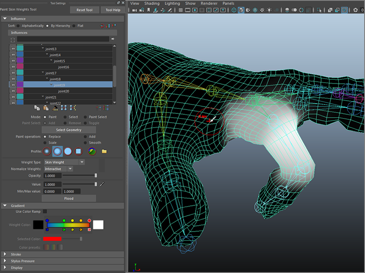
Figure 9-37: Paint the new weights to avoid unwanted deformations in the hand.
- Smooth out the area where it goes from white to black. In the option box, in the Influence section, set Paint Operation to Smooth. Right-click to smooth the area around the knuckle for a cleaner deformation, as shown in Figure 9-38. Your index knuckle should now bend beautifully.

Figure 9-38: Smoothing out the bend at the index finger
You can exit the Paint Skin Weights tool by selecting another tool (press W for Translate, for example), and your view will return to regular Shaded mode. Try bending the rest of the fingers and painting their influences; then, animate the hand, making gestures or grabbing an object using FK animation to set keys on the rotations.
The scene poly_hand_skeleton_v03.ma from the Poly_Hand_Anim project from the companion web page has the hand smooth-bound with painted weights on just the index finger for your reference. Try painting the other knuckles as needed for your animation.
Binding the Hand: Heat Map Method
Now let’s try the same exercise using a Heat Map binding method instead of Closest Distance.
Load your own hand model before it was bound or the poly_hand_skeleton_v02.ma file from the Poly_Hand_Anim project from the web page. Now, follow these steps to smooth-bind the hand with the Heat Map method to compare to the previous method you tried:
- Select the skeleton’s root at the wrist and the hand mesh and choose Skin ⇒ Bind Skin ❏. Change Bind Method to Heat Map and click Bind Skin.
- Rotate the middle knuckle of the index finger down. Go to the top knuckle of the index finger and rotate that joint as well. Notice that the bending is cleaner than before. Not much of the hand moves when you bend the index finger joints as it did in the previous exercise using the Closest Method. Figure 9-39 shows the result of bending at the index finger having used the Heat Map method of the Smooth Bind.

Figure 9-39: The index finger seems to bend more cleanly than before.
- Select the hand mesh and choose Skin ⇒ Paint Skin Weights ❏. Just as before, the hand turns black except for white areas on the mesh corresponding to the selected joint (shown in Figure 9-40 with the index finger’s joint9 selected).
- Paint weights on this hand, and you’ll notice that it is a little easier now that you’ve used Heat Map instead of Closest Distance.

Figure 9-40: Painting skin weights on the Heat Map method bound hand
The Heat Map method gives you cleaner creases and bends at the knuckles, where Closest Point was a bit more soft, often deforming parts of the hand that shouldn’t be affected much by a bending finger. There’s still some painting to be done to make the fingers bend perfectly even when using the Heat Map method. The poly_hand_skeleton_v04.ma file from the Poly_Hand_Anim project has the hand with the index finger with painted weights as a reference for you.
Binding the Hand: Interactive Bind
Now, try skinning the hand with Interactive Bind.
Load your own hand or the poly_hand_skeleton_v02.ma file from the Poly_Hand_Anim project from the web page.
The Interactive Bind method is a bit easier to control when compared to the painting of the Smooth Bind weights.
- Select the root joint at the wrist and the handMesh object and choose Skin ⇒ Interactive Bind Skin. Figure 9-41 shows the color scheme of a Volume manipulator that allows you to set the initial skin weights of the hand easily.

Figure 9-41: The Volume manipulator shows the influence of the selected joint at the wrist.
- In the Outliner, select the different joints of the hand to see how the interactive binding shows the volume influences. Then select the top knuckle of the index finger (joint9). Figure 9-42 shows the influence. Select the red circle at the end of the Volume manipulator and size it down to reduce the influence on the middle finger, as shown in Figure 9-43.

Figure 9-42: The index finger’s first knuckle influences the middle finger, too.
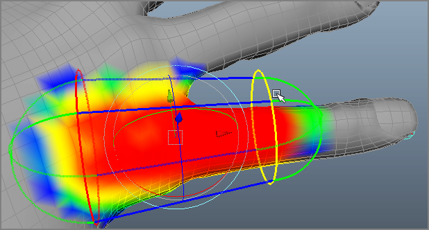
Figure 9-43: Use the Volume manipulator to reduce the influence on the middle finger.
- Grab the green spherical end, and you can see that you can move that in or out to lengthen or shorten the Volume manipulator. You can use the move or rotate handles to move the volume as well. Make adjustments to the finger to remove influences on the middle finger and other undesired areas of the hand, as shown in Figure 9-44.

Figure 9-44: Set the influences by adjusting the Volume manipulator.
Editing the interactive skin bind, as you can see, is easy using the Volume manipulators. If you exited the tool when you first created the bind and no longer see the Volume manipulators, you can access them by choosing Skin ⇒ Interactive Bind Skin Tool. When you access this tool, the Volume manipulators appear again, and you’re able to adjust your skin’s influences.
When you are happy with the proper level of influence, keep picking the other joints in the index finger to make sure your binding is proper. Then continue to the other fingers to set up the binding on the hand properly. Though this method is easier than painting weights as we did before, it is not as easy to control. Test the bind by bending the joints. Here you are using a more interactive way to bind a mesh than Smooth Bind, which may be more or less effective depending on the model you are binding. It does, however, use the Closest Distance method by default, and the Heat Map method is not available for the Interactive Bind. In addition, you can paint skin weights when you use Interactive Bind, just as you did with the regular Bind Skin.
In the case of this hand and skeleton setup, the most effective binding has been using a Smooth Bind with the Heat Map method, with some subsequent skin weight painting.
This process is pretty handy. Now, try your hand at creating a skeleton and binding it to your cartoon hand model from earlier in the book. When you’re done, congratulations, give yourself a hand!
Inverse Kinematics
With IK, you have tools that let you plant a foot where it needs to be so you’re not always moving the skeleton or model to compensate and keep the heel in place.
For legs, IK is nothing short of a blessing. There is no clearly preferable workflow to suggest for dealing with rigging arms and hands, however. Many people use IK on hands as well, but it can be better to animate the legs with IK and animate every other part of the body with FK. IK is best used when parts of the body (such as the feet) need to be planted at times. Planting the hands isn’t necessary for a walk cycle, and having IK handles on the arms may create additional work while you are animating them. You will create a more well-rounded character rig that uses IK and easy-to-use character controls at the end of the chapter. First, let’s get familiar with how IK works.
Rigging IK Legs
Let’s go back to the Block Man. Switch to that project and load your version or the block_man_skeleton_v02.ma file from the Block_Man project from the companion web page.

Figure 9-45: IK handles on both ankles with the roots at the hip joints
You’ll create an IK chain from the hip to the ankle on each foot. Creating the IK from the hip to the toe won’t work.
Because IK automatically bends the joints in its chain according to where its end effector, or IK handle, is located, it has to choose which way to bend at a particular joint. This is why you created the legs slightly bent in the Block Man rig earlier in the chapter.
If you did not do this or your setup has straight legs for whatever reason, select the two knee joints and, in Pivot mode (hold down the D key), move the knees forward a bit over the feet to create a slight crook in the legs. Don’t go too far; a slight amount is enough. This lets the IK solver know which way those joints are supposed to go.
Now, on to creating the IK:
- In the Rigging menu set, open the IK Handle tool by choosing Skeleton ⇒ Create IK Handle. Your cursor changes to a cross.
- Select the start joint for the IK chain. This will be the root of this chain. Click the left thigh joint and then pick your end effector at the ankle joint. The bones in the IK chain turn brown. Repeat this procedure for the other leg. Figure 9-45 shows handles on both ankles.
If for some reason you can’t manage to pick a joint for the IK tool, make sure Show ⇒ Pivots is turned on in your view panel. Also, if you have difficulty seeing the handles, you can increase their size by choosing Display ⇒ Animation ⇒ IK Handle Size.
- Move the IK handles around to see how the legs react. When you’re finished, reset the IK handle positions.
- Grab the top joint of the skeleton, which is the pelvis joint. Move the joint, and the entire body moves with it. Deselect the pelvis and then select the two ankle IK handles and set a translation key for them (press Shift+W). Grab the pelvis joint again and move it. The feet stick to their positions on the ground. Move the pelvis down, and the legs bend at the knees. Notice how the feet bend into the ground, though (see Figure 9-46, left).

Figure 9-46: Creating another IK chain from the ankle to the tip of the foot and setting keyframes makes the feet stay on the ground (right) and not rotate into the ground (left).
- Move the pelvis back to the origin. You can create an IK handle for the foot so that the foot stays flat on the ground. Open the IK Handle tool. For the start joint, select the first ankle; for the end effector, select the joint in the middle of that foot (lt_ballFoot or rt_ballFoot). Repeat for the other foot.
- Set a translate key for the foot IK handles. Move the pelvis down; the legs bend at the knees and the ankle, keeping the feet flush on the ground (see Figure 9-46, right).
Creating an IK Walk Animation
Because the Block Man’s feet will stick to the ground, creating a walk cycle with IK animation is far easier than using FK (“Why didn’t you tell me that before?”). Making the animation look good is still a tough job that requires a lot of practice, though.
Load the scene file block_man_IK_v01.ma from the Block_Man project from the companion web page or use your own IK-rigged Block Man with handles at the ankles and feet. The white leg and arm are, again, on the far side of the character. You’ll set keys every five frames again for the gross animation. To keep this short, I’ll just discuss setting poses with the feet. You can always return to the scene to add animation to the upper body with FK, as you did earlier in this chapter. Follow these steps:
- On frame 1, set translate keys on the pelvis joint and all four IK handles for their start position.
- Go to frame 5 and move the pelvis forward about 1 unit. The legs and feet lift off the ground a bit and strain to keep their position, but they stay back. Lower the pelvis to get the feet flat on the ground again. Set a key for the pelvis. Because Auto Keyframe is turned on, all keys are set for this animation. (With the FK animation, you set keys for everything at every pose.)
- Grab both near IK handles for the ankle and foot (blue leg) and move them forward and up to match the pose shown in Figure 9-47.

Figure 9-47: Step 3’s pose (frame 5)
- Go to frame 10. Move the front foot forward and plant it on the ground. Move the pelvis another three-fourths of a unit. Set translation keys for the rear ankle and foot handles where they are. Be sure to place the pelvis so that the rear foot is almost flat on the ground. Match the pose shown in Figure 9-48.
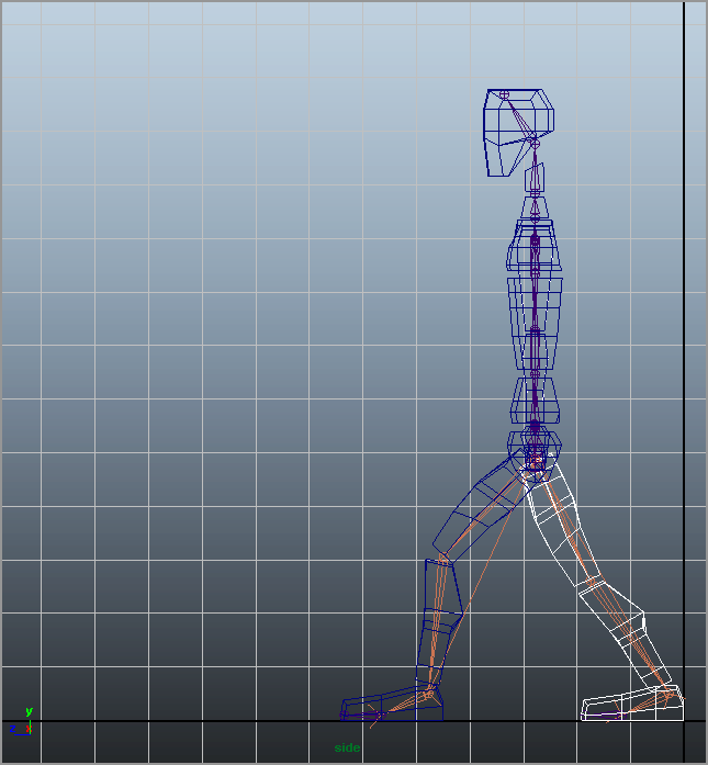
Figure 9-48: Step 4’s pose (frame 10)

Figure 9-49: Step 5’s pose (frame 15)
- Go to frame 15. Move the pelvis another 2 units to center the body over the front foot. Lift the rear ankle and foot IK handles up to bend the knee and bring the knee up a bit. Match the pose shown in Figure 9-49.
- Go to frame 20. Move the pelvis forward 1 unit and swing the white leg forward as in the pose shown in Figure 9-50.

Figure 9-50: Step 6’s pose (frame 20)
- Move the pelvis three-fourths of a unit forward and plant the front leg down. Set keys for the rear leg and foot where they stand. Match the pose shown in Figure 9-51.

Figure 9-51: Step 7’s pose (frame 25)
The next pose should match the pose in frame 10, although with the other leg. Continue the cycle, with each successive pose matching the one 15 frames before it on the opposite side.
At the end of this chapter, you’ll take this process one step further and create a simple character animation rig for the entire Block Man so you can have a nicely functioning character for animation.
Further Uses for IK Chains
Many animators use IK chains more often in effects animation than in character work. IK chains can drive whips and ropes, flutter flags, bounce ponytails, and pump pistons as well as move legs and arms. For example, you can use a different type of IK chain, the spline IK chain, to control the shape of your bone chain with a NURBS spline. This IK chain is great for snakes and other long, deforming objects.
To create a spline IK chain, choose Skeleton ⇒ Create IK Spline Handle and then select your top joint and end effector. Maya creates a spline running the length of the bone chain. Adjusting the curvature of the spline in turn drives the bones, which in turn drive the geometry bound to them. Figure 9-52 shows a spline curve affecting the curvature of the bones in its spline IK chain.

Figure 9-52: A spline IK chain is driven by the curvature of a NURBS spline. Adjusting the curve’s CVs moves the joints.
Basic Relationships: Constraints
As you know, Maya is all about the relationships between object nodes. You can create animation on one object based on the animation of another object by setting up a relationship between the objects. The simplest way to do that (outside of grouping) is to create a constraint. For example, you can “glue” one object to another’s position or rotation through a constraint.
A constraint creates a direct relationship between the source and the target object’s Translate, Rotate, or Scale attributes. This section explores six types of constraints: point, orient, scale, aim, geometry, and normal.
The Point Constraint
To attach a source object to a target object but have the source follow only the position of the target, use a point constraint. A point constraint connects only the Translate attributes of the source to the target. To use this method, select the target objects and then Shift+click the source object. In either the Animation menu set (F4) or the Rigging menu set (F3), choose Constrain ⇒ Point ❏.
Constraints are based on the pivots of the objects, so a point constraint snaps the source at its pivot point to the pivot point of the target and keeps it there, even in animation. But the options allow you to set an offset that creates a gap between the source and the target.

Figure 9-53: A cone point that is constrained to a sphere follows that sphere’s position.
You can constrain the same source to more than one target object. The source then takes up the average position between the multiple targets. By setting the Weight slider in the option box, you can create more of an influence on the source by any of the targets.
In Figure 9-53, a cone has been point-constrained to a sphere. Wherever the sphere goes, the cone follows. This is different from parenting the cone to the sphere in that only its translations are affected by the sphere. If you rotate or scale the sphere, the cone won’t rotate or scale with it.
Although you can blend keyframe animation with constraint animation, as a beginner to Maya, consider that after you set a point constraint like that shown in Figure 9-53, you’re unable to control the cone’s Translate attributes because they’re being driven by the sphere’s translations.
Point constraints are perfect to animate a character carrying a cane or a sword, for example. The rotations on the sword are still free to animate, but the sword is attached to the character’s belt and follows the character throughout the scene.

Figure 9-54: The cone’s rotations match the sphere’s rotations.
The Orient Constraint
An orient constraint attaches the source’s Rotation attributes to the target’s Rotation attributes. Select the target object or objects first, then Shift+click the source object, and then choose Constrain ⇒ Orient ❏.
The Offset parameter allows you to set an offset in any axis. Otherwise, the source assumes the exact orientation of the target. In the case of multiple targets, the source uses the average of their orientations. Figure 9-54 shows the cone’s orientation following an elongated sphere (the target).
A rotation constraint saves a lot of hassle when you have to animate an object to keep rotating in the same direction as another object. For example, you can use the rotation of one wheel of a locomotive to drive the rotation of all the other wheels.
The Point on Poly Constraint
A point on poly constraint attaches a source object to a vertex of a mesh. Select the target object’s vertex first and then Shift+click the object you want to place at that point (see Figure 9-55, left). In the Animation or Rigging menu set, choose Constrain ⇒ Point On Poly ❏.

Figure 9-55: The red ball is placed on the tree branch like a fruit with a point on poly constraint.
The object is snapped to the vertex of the target at its pivot point. Even if the target object is animated and deforming, like a character, the object will stay on that vertex. Figure 9-55 (right) shows the sphere pinned to the branch at the selected vertex location.
The point on poly constraint is good for pinning objects together, such as leaves on a branch.
The Aim Constraint
The aim constraint adjusts the source’s rotations so that the source always points to the target object. Select the target objects first and then Shift+click the source object. In the Animation or Rigging menu set, choose Constrain ⇒ Aim ❏.
The aim constraint has more options than the other constraints because you need to specify which axis of the source is to point to the target. You do so using the Aim Vector and Up Vector settings.
The Aim Vector setting specifies which axis of the source is the “front” and points to the target. In the cone and sphere examples, you set the Aim Vector option of the cone to (0,1,0) to make the Y-axis the front so that the cone’s point aims at the sphere. If Aim Vector is set to (1,0,0), for example, the cone’s side points to the sphere. Figure 9-56 shows the cone pointing to the sphere with an Aim Vector setting of (0,1,0).

Figure 9-56: The cone aiming at the sphere
The Offset values create an offset on the source’s Rotation attributes, tilting it one way or another. The Up Vector setting specifies which way the cone faces when it’s pointing to the sphere.
Aim constraints are perfect for animating cameras to follow a subject, such as a car at a racetrack.
Geometry and Normal Constraints
The geometry and normal constraints constrain the source object to the surface of the target object (as long as it’s a NURBS or poly mesh).
With a geometry constraint, the source object attaches, at its pivot point, to the surface of the target. It tries to keep its own position as best it can, shifting as its target surface changes beneath it. Again, select the target, select the source object, and choose Constrain ⇒ Geometry.
A geometry constraint is useful when you want to keep an object on a deforming surface, such as a floating boat on a lake. Figure 9-57 shows the cone after it has been geometry-constrained to a NURBS plane that is being deformed by a Wave deformer (in the Rigging menu, set choose Deform ⇒ Nonlinear ⇒ Wave). The cone sits on the surface as the waves ripple through, but it doesn’t rock back and forth to stay oriented with the surface.

Figure 9-57: With a geometry constraint, the cone sits on the deforming surface.
To get the cone to orient itself so that it truly floats on the surface, you need to use a normal constraint. Using a normal constraint rotates the cone to follow the surface’s normals, keeping it perpendicular to the surface.
The normal constraint is similar to the aim constraint, and its options are similar. Using the Aim Vector setting, you specify which way is up for the object to define the orientation that the source should maintain. However, this setting doesn’t constrain the location of the source to the target. If you want a floating effect, use geometry and a normal constraint to get the cone to bob up and down and roll back and forth as the waves ripple along (see Figure 9-58).

Figure 9-58: The cone now animates to float on the water surface, using both geometry and normal constraints.
Scale, Parent, Tangent, and Pole Vector Constraints
Four more constraints are possible in Maya: the scale, parent, tangent, and pole vector constraints. Simply, a scale constraint attaches the source’s Scale attributes to the target’s Scale attributes. A parent constraint constrains an object’s translation and rotation to another object by mimicking a parent-child relationship without actually parenting the objects. This keeps objects aligned without worrying about any grouping issues. You’ll have a firsthand look at this in the exercise where you rig the locomotive later in this chapter. Lucky you!
A tangent constraint keeps an object’s orientation so that the object always points along a curve’s direction. This constraint is usually used with a geometry constraint or path animation to keep the object traveling along a curve pointed in the right direction, no matter the direction of the curve. A point on poly constraint allows you to select a vertex on a poly mesh and constrain an object to that vertex. Pole vector constraints are used extensively in character animation rigs to keep IK joints from flipping beyond 180 degrees of motion.
Basic Relationships: Set-Driven Keys
A favorite feature for animation riggers is the set-driven key (SDK). An SDK establishes a relationship for objects that lets you create controls that drive certain features of a character or an object in a scene.
Before you can use an SDK, you must create extra attributes and attach them to a character’s top node. These new attributes drive part of the character’s animation. The term character is used broadly here. For example, you can set up a vehicle so that an SDK turns its wheels.
Let’s start with a simple SDK relationship between two objects. You’ll create a relationship between a ball and a cone. As the ball moves up in the Y-axis, the cone spins in the X-axis. As the ball descends, the cone spins back. You’ll then revisit the hand and set up an SDK on the skeleton that animates the model.
Creating a Set-Driven Key
To create a simple SDK to make a sphere control the animation of a cone’s rotation, follow these steps:
- Create a Poly sphere and a poly cone in a new scene. Move the cone to the side of the sphere and lay it on its side, as shown in Figure 9-59.

Figure 9-59: Lay out a cone and a sphere.
- Select the sphere and, in the Animation menu set, choose Key ⇒ Set Driven Key ⇒ Set. The Set Driven Key window opens with the pSphere1 object selected in the lower half of the window (the Driven section). Its attributes are listed on the right, as shown in Figure 9-60.

Figure 9-60: The Set Driven Key window
- You want the sphere to drive the animation of the cone, so you need to switch the sphere to be the driver and not what’s driven. Click the Load Driver button to list the sphere in the top half of the window.
- Select the cone and click the Load Driven button to display the cone’s attributes in the bottom half of the window.
- In the Driver section, select the sphere’s Translate Y attribute. In the Driven section, select the cone’s Rotate X attribute. Click the Key button to set an SDK that essentially says that when the sphere is on the ground (Y = 0), the cone’s X rotation is 0 because both attributes are currently 0. The cone’s Rotate X attribute turns orange in the Channel Box, meaning a driven key has been set.
- Select the sphere and raise it in Y to a height of 5. Select the cone and rotate it in X to 1800 to make it spin properly. Click the Key button in the Set Driven Key window to specify that when the sphere is at a height of 5, the cone’s Rotate X attribute is 1800 degrees. As the sphere’s height increases from 0 to 5, the cone spins from 0 to 1800 in X.
An Advanced Set-Driven Key: The Hand
Automating some animations on a character is indispensable to an animator. This can’t be truer than when setting up an SDK for hand control. After you model and bind a hand to a skeleton, you’re ready for an SDK.
Open the scene poly_hand_skeleton_v05.ma from the Poly_Hand_Anim project from the companion web page or use your own file that has the hand and its skeleton and is bound to the skin. Your file shouldn’t have animation, though. Set your hand to the bind pose before you begin.
Creating a New Attribute
First you’ll create a new attribute called index_pull to control a contracting finger.
- Select the hand. In the handMesh tab of the Attribute Editor, click the Extra Attributes section. For now, at least, this section is empty.
- In the Attribute Editor's menu bar, choose Attributes ⇒ Add Attributes to open the Add Attribute window, which is shown in Figure 9-61. In the Long Name field, enter index_pull. Maya will automatically display that attribute as Index Pull in the UI. Make sure the Make Attribute Keyable option is selected and that the Float option is selected in the Data Type section. In the Numeric Attribute Properties section, set Minimum to 0, Maximum to 10, and Default to 0. Click OK.

Figure 9-61: The Add Attribute window
After you click OK, the Index_Pull slider appears in the Attribute Editor and the Channel Box when you select the handMesh object. This attribute alone will control the entire index finger.
Assigning the Set-Driven Key
To set up the relationships with the SDK, follow these steps:
- With the handMesh selected, open the Set Driven Key window (choose Key ⇒ Set Driven Key ⇒ Set). Click Load Driver to specify that the hand should drive the animation.
- Because you’re animating the index finger pulling back, you want to drive the rotations of the top three knuckles. Deselect the hand, and then Shift+click all three knuckles on the index finger to select them. Click the Load Driven button. All three knuckles appear on the bottom.
- Select the hand’s Index Pull attribute (although you named the attribute index_pull, Maya will display it as Index Pull in the Set Driven Key window and a few other places like the Channel Box) and the three knuckles’ Rotate Y attributes, as shown in Figure 9-62.

Figure 9-62: The Set Driven Key window for the hand
- With the rotations of the knuckles at 0 and the Index Pull attribute at 0 as well, click the Key button to set the first relationship. When Index Pull is at 0, the finger is extended.
- Select the handMesh node and set the Index Pull attribute to 5.
- Select the fingertip’s knuckle (joint11 in the web page file) and rotate it in Y to 20. Select the next joint up the chain (the middle knuckle, joint10) and rotate it to 35 in the Y-axis. Select the final index knuckle (joint9) and rotate it in the Y-axis to 5.
- In the Set Driven Key window, select the three joints’ Rotate Y and the handMesh Index Pull attribute and click the Key button. When the Index Pull attribute is at 5, the finger assumes this bent position.
- Select the handMesh and set Index Pull to 10.
- Set the tip knuckle (joint11) to rotate to 65 in Y. Set the middle knuckle (joint10) to 60. Set the last knuckle (joint9) to 50. Click the Key button to see the result shown in Figure 9-63.
Select the handMesh node and change the value of the Index Pull attribute to curl your index finger. All you need to do to animate the finger is to set keys on that one attribute! Furthermore, you can set up a single SDK to control the bending of all the fingers at once, or you can set up one SDK for each finger for more control.
Open the scene poly_hand_skeleton_v06.ma from the Poly_Hand_Anim project available on the companion web page to see the hand with the SDK set up on the index finger.

Figure 9-63: The bent index finger
Rigging the Locomotive
In this section, you’ll use a locomotive to put your new animation skills to use. Download the file fancy_locomotive_anim_v1.mb from the Scenes folder of the Locomotive project from the book’s web page; this scene is shown in Figure 9-64. Notice in this scene there are small plus signs near the wheels. These are selection handles, allowing you to more easily select objects or groups of objects. They have been enabled for some of the objects on the locomotive to make it easier to work with. To toggle selection handles on or off for any node in Maya, select Display ⇒ Transform Display ⇒ Selection Handles.

Figure 9-64: The fancier locomotive model
After selection handles for the locomotive’s wheels and drive arms are turned on, only the objects that have selection handles will be selected when you make a marquee selection that covers the entire locomotive.
Setting Up Wheel Control
Your goal here is to rig the scene to animate all the secondary movements automatically based on some simple controls, like you did for the hand earlier this chapter. In reality, the locomotive’s steam pump drives the arms that then turn the wheels on the locomotive. You’ll work backward, however, and use one wheel to drive the animation of everything else.
Because all the large wheels have the same diameter, they rotate the same as the locomotive moves. In this case, you’ll use the Connection Editor to attach the X Rotation on all the wheels to your main control wheel. You’ll pick the middle wheel to be the control. To set up the locomotive, follow these steps:

Figure 9-65: Select the middle wheel.

Figure 9-66: Connect the rotations of the two wheels.
- Select the middle wheel on the left side of the locomotive (node wheel_2_LT_side), as shown in Figure 9-65. Open the Connection Editor (choose Windows ⇒ General Editors ⇒ Connection Editor). Click the Reload Left button to load the attributes of the selected middle wheel. Now, select the front wheel on the left side and click the Reload Right button.
- Scroll down in the Connection Editor until you find Rotate in both columns. Click to highlight Rotate in the left column and then click to highlight Rotate in the right column. Doing so connects the two rotations so that they both rotate at the same time, effectively letting you drive the animation of both wheels from just the center wheel. Figure 9-66 shows the Connection Editor.
- Select the back wheel on the left side (wheel_3_LT_side). Click the Reload Right button in the Connection Editor. Connect the Rotate attribute for the middle and back wheels. Close the Connection Editor and select just the middle wheel. When you rotate the wheel, all three wheels rotate together.
- Repeat this procedure to connect the rotations of the three wheels on the other side to this middle wheel as well. Now all six wheels rotate in sync with the one control wheel. When you select that left-side middle wheel (the control wheel), the other five wheels turn magenta, signifying a connection between these objects.
Controlling the Wheel Arms
You’ve now automated the animation of the wheels. Next, you’ll figure out how to connect the wheel arms to the wheels and drive their motion as well. To do so, follow these steps:
- Create a single joint that lines up with the first wheel arm. The root joint is placed where the wheel arm meets the middle wheel (control wheel), and the end joint is placed where the wheel arm meets the pump arm, as shown in Figure 9-67. The pump arm has been templated in this graphic (displays in light gray wireframe) to show you the entire wheel arm and joint.

Figure 9-67: Create a joint from the middle wheel to the pump arm at the first wheel.
- Group the joint under the control wheel’s node, as shown in the Outliner, earlier in Figure 9-65. Then, group the wheel arm under the top joint. This way, the joint rotates with the control wheel, also shown in Figure 9-68, albeit incorrectly for the pump arm.
- As you saw in Figure 9-68, the joint isn’t rotating properly to make the pump arm work right. The other end of it needs to attach to the pump arm in front of the front wheel, not fly up in space. You can use an IK handle for this. Make sure the rotation of the control wheel and the joint/wheel arm are set back to 0 to place them in the original position. In the Rigging menu set, choose Skeleton ⇒ Create IK Handle. Make sure the settings are reset for the tool. Select the root joint as the start joint for the IK handle. Select the other tip of the bone as the end effector. You now have an IK handle at the tip where the wheel arm connects to the pump arm, as shown in Figure 9-69.

Figure 9-68: Group the top joint under the wheel and then group the wheel arm under the top joint.

Figure 9-69: Place the end effector where the pump arm and the first wheel connect.
- If you rotate the control wheel now, the wheel arm still separates from the pump arm. This is because the IK handle you just created needs a keyframe to keep it in position—that is, attached to the pump arm. Select the IK handle and, at frame 1, set a position keyframe. Now, if you rotate the control wheel, the joint and wheel arm pump back and forth.
- Group the IK handle (ikHandle1) under the top node of the locomotive (wholeLoco), as shown in Figure 9-70.

Figure 9-70: Group the IK handle under the locomotive’s top node.
Controlling the Pump Arm
Next, you need to attach the pump arm to the wheel arm so that it pumps back and forth as the control wheel turns. If you simply group the pump arm with the end joint of the wheel arm’s bone, the pump arm will float up and down as it pumps back and forth. You need to use a constraint to force the pump arm to move back and forth only in the Z-axis.
- Make sure the control wheel is set back to 0 rotation. Select the pump arm, templated in Figure 9-71 so that you can see through to the wheel arm and joint, and line up its pivot with the end joint of the wheel arm bone.

Figure 9-71: Line up the pivot of the pump arm with the end joint of the wheel arm joint.
- Select the end joint (called joint2), Ctrl+click (or Cmd+click on a Mac) the pump arm group in the Outliner (called pump_arm_LT_side), and in the Rigging menu set choose Constrain ⇒ Point ❏. In the option box, under Constraint Axes, select only Z to constrain the pump arm only in the Z-axis and click the Add button. Now if you rotate the control wheel, you see the pump arm and wheel arm connected. The pump arm pumps back and forth, although you’ll immediately notice a need to adjust the model to make the piece fit when it animates. Figure 9-72 shows that the pump arm’s geometry isn’t yet quite right for animation. This is normal for this process and luckily needs only a quick fix.
- To fix the pump arm, select the vertices on the ends of the cylinders and extend them to make them longer, as shown in Figure 9-73. Now the pump arm won’t pull out of the steam pump assembly.
- Adjust the pump arm so that the geometry fits when the pump pushes in as well.
The scene file fancy_locomotive_anim_v2.mb will catch you up to this point. Compare it to your work.

Figure 9-72: The pump arm is too short!

Figure 9-73: Use vertices to extend the pump arm.
Controlling the Back Wheel
All that remains is to control the animation of the back wheel and its wheel arm. To set up the wheel arm animation, follow these steps:
- Using the methods described in the steps in the “Controlling the Wheel Arms” section, create a joint to follow along the wheel arm between the middle control wheel and the back wheel. The root of the joint is set at the control wheel, as shown in Figure 9-74.

Figure 9-74: Create a joint to control the back wheel arm.
- As before, create an IK handle for the end joint of this new bone, where it meets the back wheel, as shown in Figure 9-75. Make sure the handle is at the back wheel, not the middle control wheel.
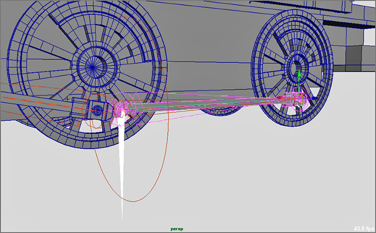
Figure 9-75: Create an IK handle to attach the wheel arm and the back wheel to the control wheel.
- Group the new joint under the master wheel and then group the wheel arm under this new joint. If you rotate the control wheel, the wheel arm rotates with the joint and wheel but doesn’t connect to the back wheel yet. You need to attach the IK handle you just created for that joint to the back wheel.
If you group the IK handle, as shown earlier in Figure 9-70, you’ll run into a problem when you animate. Let’s try it. Group the IK handle (ikHandle2) under the end back wheel, as shown in Figure 9-76, and then rotate the control wheel. The wheel arm pumps back and forth along with the back wheel, but every now and then the wheel arm geometry flips over backward. This isn’t good.

Figure 9-76: The wheel arm geometry flips over if you group the IK handle under the back wheel.
Fixing this is easy. The grouping of the IK handle to the back wheel is causing the issue. Although that is pretty much what you want to do, parenting the IK handle under the wheel is problematic. Here is where the parent constraint becomes extremely helpful. It gives you the desired result without the geometry flipping.
- Make sure your control wheel is back to 0 rotation first. MMB+click in the Outliner and place the IK handle outside the hierarchy of the locomotive to remove the IK handle from under the back wheel’s node. You may also undo your past actions to the point before you grouped the IK handle (ikHandle2) under the back wheel. (You have to love Undo!)
- Select the back wheel, Shift+click the IK handle (ikHandle2), and choose Constrain ⇒ Parent. Now, if you rotate the control wheel, everything works great.
- Group the IK handle (ikHandle2) under the top node of the locomotive (wholeLoco).
You can use fancy_locomotive_anim_v3.mb to compare your work.
Finishing the Rig
You’re almost home free with the locomotive wheel rigging. Everything works great when you rotate the control wheel. If you select the top node of the locomotive and translate the train back and forth, everything should work perfectly. Repeat the steps in the previous few sections to connect the wheel arms and wheels on the other side of the locomotive, and you’re finished! Figure 9-77 shows the completed and rigged locomotive.

Figure 9-77: The rigged fancy locomotive
Creating a Simple Character Rig
In this section, you will revisit the Block Man setup to create a more well-rounded character rig with controls like professional animators use. This rig was created by Maks Naporowski, a fellow instructor at USC and CG animator/rigger, as a fairly simple biped rig for animation. Bear in mind that character rigging is an involved process, and you are starting to scratch the surface here. When you are done with this rig, you will have a simple two-legged character that you can easily animate using the controls you will set up based on what you’ve already accomplished throughout this chapter.
Creating Control Shapes
Animators hardly ever manipulate and keyframe IK handles or joints directly when a good rig is available to them, and that’s what you should keep in mind for the following rig:
- Open the scene file
block_man_skeleton_v02.mafrom the Block_Man project. - In the Rigging menu set, choose Skeleton ⇒ Create IK Handle ❏. In the option box, set the Current solver attribute to Rotate-Plane Solver. Click one of the hip joints and then click the ankle joint. This makes an IK chain for the leg. Repeat for the other leg. Name them lt_ikHandle and rt_ikHandle.
- Create an IK chain for the arms, from the shoulder to the wrist, also making sure to use the Rotate-Plane Solver. Name them as well. Figure 9-78 shows all four IK handles created.

Figure 9-78: Create IK handles for the arms and legs.
- Create a circle (Create ⇒ NURBS Primitives ⇒ Circle). Scale it up and center it around the left wrist. Name this circle lt_arm_CNTRL. Duplicate the circle, move the copy to center on the right wrist, and name it rt_arm_CNTRL. Refer to Figure 9-79 for placement.

Figure 9-79: Create circles for the wrists, place them, and assign them to their own display layers.
- In the Channel Box/Layer Editor, click the Display tab in the Layer Editor and create two new layers: lt_cntrls (make it blue) and rt_cntrls (make it red). Assign the left wrist circle to lt_cntrls and the right wrist circle to rt_cntrls. This makes it easier to visualize and control. (See Figure 9-79.)
- Select both circles and select Modify ⇒ Freeze Transformations. This will zero out their positions. Name the left wrist circle lt_arm_CNTRL and the right wrist circle rt_arm_CNTRL.
- Create two more circles and adjust their CVs to make them oval to fit around the feet. Size and place them around the feet as shown in Figure 9-80. Assign each foot oval to the appropriate lt_cntrls or rt_cntrls display layers and name the ovals lt_foot_CNTRL and rt_foot_CNTRL, respectively.

Figure 9-80: Create control shapes for the feet, pelvis, and body.
- Create a large circle and center it around the pelvis joint (name it body_CNTRL). Make another large square shape and place it on the floor around the feet (name it main_CNTRL). Assign these two shapes to a new display layer called cn_cntrls and make it green.
These shapes will be the primary controllers for the animation of the character. They are easy to select and manipulate and make animation much easier.
Setting Up the Controls
Now comes the tough part of rigging it all to work! You’ll group the shapes and create relationships to the skeleton here:
- Parent the body_CNTRL under the main_CNTRL shape.
- Parent the two arm controllers (rt_arm_CNTRL and lt_arm_CNTRL) under the main_CNTRL shape as well.
- Parent each of the two wrist IK handles under each respective circle shape, as shown in Figure 9-81.

Figure 9-81: Grouping the controllers and IK handles
- Select the left wrist circle and the lt_wrist joint and choose Constrain ⇒ Orient ❏. In the option box, turn on Maintain Offset and click Add.
This allows you to control the hand’s rotation with the circle, as well as the hand’s position. Select the wrist circle and move and rotate it around to see how the arm reacts. The elbow can swing around a little much, so you’ll add a control for the twist of the arm.
- Select the left wrist circle and open the Attribute Editor. Choose Attributes ⇒ Add Attribute. Enter the name twist to the wrist circle and keep the options at their default (Data Type: Float).
- Now you’ll connect it to the IK handle. Select the left wrists’ IK handle and also its circle controller and choose Windows ⇒ Node Editor. You will see two nodes in the Node Editor (see Figure 9-82, top). Click once on the View Mode icon (
 ) on the right of each node to expand its view, as shown in Figure 9-82 (bottom).The white and colored circles on either side of the nodes are input and output sockets.

Figure 9-82: The Node Editor displays the IK handle and the circle control shape in compact display (top). The nodes with expanded display show attributes (bottom).
- Click the output socket of the lt_arm_CNTRL node (the green circle on the right) next to the Twist attribute and drag the cursor to reveal a yellow rubber band attached to your cursor. Drag the mouse to the input socket of the lt_wrist_ikHandle node’s Twist attribute (the light blue circle on the left) and release the mouse button. This connects these two attributes; however, the Node Editor doesn’t show the connection immediately. To see the actual connection, click the lt_arm_CNTRL node in the Node Editor and click the Input And Output Connections icon (
 ) at the top of the window. You’ll now see the connection is made through an intermediate node (unitConversion1), as in Figure 9-83.

Figure 9-83: You’ve connected the Twist attributes, though you can’t see it until you click Input And Output Connections icon, which is kind of silly.
You can ignore this extra node, but rest assured that the connection is made. Clicking the Input And Output Connections icon (
) is always a good idea to check your connections in the Node Editor. - Now if you select the wrist circle and adjust the twist value, the arm will twist. If nothing happens, check your node connection and make sure you used the ikRPsolver when you created the IK handles in the previous section.
- Repeat steps 4 through 8 for the right hand.
- Now let’s do the same for the feet for the Twist attribute. Select the left foot’s control oval and add a new attribute called twist. Select the oval and the ankle joint (lt_ikHandle1) and open the Node Editor and connect the Twist attributes as you did in step 7 for the arm. Repeat for the right leg.
- Select the pelvis joint and parent that under the body_CNTRL circle.
Setting Up Heel Controls
Now let’s move on to creating some nice foot controls to allow the character to stand on his tiptoes or his heels easily. For that you will need to build a reverse joint chain to control the foot from the heel to supplement the existing leg joints.
- In the side view, choose Skeleton ⇒ Create Joints and place a joint at the back of the left heel, as shown in Figure 9-84. Place the second joint exactly on the existing toe joint (lt_foot). Hold down V for point snaps when you create the joint so you can snap it exactly to that toe joint. Snap the third joint to the existing lt_ballFoot joint; finally, snap the fourth joint to the existing lt_ankle joint.

Figure 9-84: Create a reverse joint chain for the left foot.
- Grab the top joint of this reverse chain and parent it under the lt_foot_CNTRL oval. Name the joints as noted in Figure 9-85. Finally, parent the left ankle’s IK handle (lt_ihHandle1) under the lt_rev_ankle joint as shown. Repeat for the other foot.

Figure 9-85: Parent the heel joints and ankle IK handles.
- Next, parent both the foot control ovals under the main_CNTRL square. (See Figure 9-86.)

Figure 9-86: Parent the foot controls.
- Select the main_CNTRL square and move the rig around. The character moves along with it. Select the body_CNTRL circle. When you move the body control, the feet and hands stay because of IK (see Figure 9-87), and that’s how you want it. Undo your moves.
- Create a display layer called rigging. Select the lt_rev_heel and rt_rev_heel joints you just created and parented and assign them to the new rigging display layer. This will make it easy to hide these extra reverse joints to keep them out of the way later.
- Select the lt_rev_toes joint first and then the lt_ballfoot joint (see Figure 9-88 for the selections) and choose Constrain ⇒ Orient ❏. Make sure Maintain Offset is checked and click Apply. The constraint node should appear under the lt_ballFoot node, as shown in the Outliner in Figure 9-88 (left image).
- Select the lt_rev_ballFoot joint and then the lt_ankle joint and create an aim constraint like in the previous step.
- Repeat steps 6 and 7 for the right foot.
- When you’re done, your Outliner should be similar to the one shown in Figure 9-88 (right image). If your constraint nodes are not in the right places, check to make sure you selected the nodes in order in steps 6 and 7 when you made the aim constraint.

Figure 9-87: Moving the body control and the main control works perfectly.

Figure 9-88: Aim constrain the two joints together.
Set-Driven Keys: Heel Controls
Now let’s set up some fancy heel controls.
- Select the left foot control oval and add a new attribute to it called heel. In the options, change Data Type to Float, but give it a Minimum of –5 and a Maximum of 10 (see Figure 9-89). Repeat for the right foot.

Figure 9-89: Create a new attribute for the foot control oval.
You need to set up a set-driven key to raise or lower the heel based on the value of the Heel attribute.
- Select the left foot control oval and choose Key ⇒ Set Driven Key ⇒ Set from the Animation menu set. Click Load Driver to load the control oval as the driver of this SDK.
- Select lt_rev_heel and click Load Driven in the SDK window.
- In the SDK window, select Heel as the driver attribute on the oval and the RotateZ attribute on the driven joint (see Figure 9-90).

Figure 9-90: The first SDK relationship for the reverse heel joint
- Make sure the Heel attribute is set to 0 and the Rotate Z for the lt_rev_heel joint is also 0. Click Key in the SDK window.
- Set the Heel attribute to –5 and rotate the lt_rev_heel 45 degrees up in Z. Click Key in the SDK window. If you now select the foot control oval and change the Heel attribute to between –5 and 0, the heel will raise and lower. Make sure to set it back to 0 when you’re done testing.
- Select the lt_rev_ballFoot joint and click Load Driven in the SDK window. Keep lf_foot_CNTRL’s Heel as the driver. Select the RotateZ attribute for the driven joint (see Figure 9-91.)

Figure 9-91: The next SDK relationship for the reverse ballFoot joint
- Set Heel to 0 and rotate in Z for the rev_ballFoot to 0. Click Key in the SDK window.
- Set Heel to 5 and rotate in Z for the rev_ballFoot to 45 degrees. Click Key in the SDK window.
- Set Heel to 10 and rotate in Z for the rev_ballFoot back to 0. Click Key in the SDK window.
- Test the Heel slider by sliding it to a value of 5, and you should see the back of the foot moving up, as shown in Figure 9-92. Set Heel to 10, and the heel comes back down.
- Finally, select lt_rev_toes and click Load Driven in the SDK window. Keep lf_foot_CNTRL’s Heel as the driver. Select Rotate Z as the driven channel for the lt_rev_toes joint in the SDK window. Figure 9-93 shows the SDK relationship.
- Set Heel to 5 and make sure the lt_rev_toes joint’s Rotate Z is 0. Click Key in the SDK window.
- Set Heel to 10 and rotate in Z the lt_rev_toes joint to 45 degrees. Click Key in the SDK window.

Figure 9-92: When the Heel attribute is at 5, the heel should raise up like shown.
- Test the Heel slider, and you’ll see at a value of 10 that the foot is up and the toes are on the ground (see Figure 9-94).

Figure 9-93: The final SDK relationship for the reverse toe joint

Figure 9-94: The foot position when Heel is set to 10
- Repeat steps 1 through 15 for the right foot. This time, you will use the rt_ nodes in place of the lt_ nodes you used earlier.
Make sure you’re saving your progress as you go! When you’re done, your rig should have some pretty handy controls. You will move the entire character using the main_CNTRL node. You can move the body itself while keeping sticky IK hands and feet by using the body_CNTRL node. And, of course, you control the arms/hands and legs/feet using the respective arm_CNTRL and foot_CNTRL nodes. All keyframes and animation should happen on these nodes only; you should not have to manipulate the joints or the IK handles directly at all. And that, in a somewhat long-winded nutshell, is the purpose of a character rig.
You can load the file character_rig_v01.ma from the Block_Man project to check your work or just to use as a rigged character for some animation fun!
For Further Study
Animation is as much a sport as it is an art, meaning practice makes you better. Use the rigged character from the end of this chapter to redo the walk animations from the beginning of the chapter. Also try different types and moods of walk. Can you animate a simple walk that looks happy and enthusiastic? Can you make that walk sad and lonely? Being able to convey emotion in your movement is key, and the more you try, the better you get.
Summary
In this chapter, you extended your experience with animation and learned about rigging techniques and automation. Starting with the simple Block Man, you learned how to set up a hierarchy for forward kinematics animation to create a walk cycle. Then, you used a skeleton to rig a hand for animation. Next, you learned how to bind the geometry of the hand to the skeleton using two different methods of smooth bind and also the interactive bind, as well as how to edit the binding. You also learned how to create an IK system to drive the joints in the Block Man for an IK walk cycle animation. After that, you learned how constraints can be used in rigging and how to set up set-driven keys to create easy controls to animate the hand. Then, you put all these rigging tricks together to rig the wheels of the locomotive to automate the animation of that complex system with a single control based on the middle wheel. And finally, you tackled a pretty tough rigging assignment in rigging the Block Man even further to have some nice options for movement using controllers.
The true work in animation comes from recognizing what to do in the face of certain challenges and how to approach their solutions. Maya offers a large animation toolset, and the more familiar you become with the tools, the better you’ll be able to judge which tools to use in your work. Don’t stop with this chapter; experiment with the features not covered here to see what happens.
Animation is about observation and interpretation. The animator’s duty is to understand how and why something moves and to translate that into their medium without losing the movement’s fidelity, tenacity, or honesty.