
Chapter 6
Practical Experience!
It’s time to put what you’ve learned so far into action. In this chapter, you’ll build a child’s airplane toy. The plane project uses poly and NURBS modeling techniques to give you some practical experience with a larger project in the Autodesk® Maya® software.
- Learning Outcomes: In this chapter, you will be able to
- Use bevels and extrusions efficiently
- Manipulate curves to create poly meshes with Revolves and Loft Surfaces
- Create a shape with a path extrusion
- Use reference images to shape your models
- See how to set up views with grid lines to align reference images for modeling
- See how images are lined up to make reference images for modeling
- Work in the Hypershade to assign image maps to objects in the scene
- Use a Boolean operation to cut holes in a mesh
Evaluating the Toy Plane
Download the entire Plane project folder structure from the book’s companion web page (www.sybex.com/go/introducingmaya2016) to your computer’s hard drive and set your project to that location.
Also on the book’s website (as well as the author’s site www.koosh3d.com) are video tutorials taking you through parts of this exercise.
Figure 6-1 shows a bathtub toy airplane that you’ll be modeling first in this chapter. There’s certainly enough detail in this object to make it a good exercise, but it won’t be difficult to complete. You can always return to this exercise to add more of your own detail or even redesign it for more challenge, which is something I highly recommend.

Figure 6-1: The toy plane is cute!
Study the photos (Figure 6-1, Figure 6-2, and Figure 6-3) carefully to get an understanding of the components that make up this object. You will model the parts individually instead of attacking the entire shape as a single object. This way of thinking helps complex objects become easier to understand and model. The plane consists of the body, landing pontoons, engine/propeller, stabilizer wings, and main wings, as shown in Figure 6-1. In Chapter 3’s decorative box exercise, you used reference planes to give you an accurate guide to build the box, and you’ll do the same with the individual parts of the plane.

Figure 6-2: The side photo of the plane

Figure 6-3: The top photo of the plane
Building the Landing Pontoons
Let’s start with the landing pontoons. You need to model only one and then make a duplicate and mirror it for the other side.
Reference Images
First you need to assemble the reference planes to make the model easier to build. Figure 6-4 shows the top, side, and front views of a pontoon scaled and lined up in Adobe Photoshop. I copied and pasted the individual photos into a larger image and then used grid lines to line up the proportions of the pontoon. Keep in mind that when you take a photo, in most cases there will be perspective shift, or parallax, in the image. Because of that shift, the different views of the same object will never exactly line up. Once each individual photo is scaled and lined up like in Figure 6-4, you can output each image as its own file to bring into Maya for top, side, and front references.

Figure 6-4: The reference photos of the pontoon are lined up.
Now, you’ll import the images and create the model reference planes on which to work.
Creating Reference Planes for the Images
The reference images of the toy airplane have already been created for you. You can find them in the Sourceimages folder of the Plane project on the companion website. They’re shown in Table 6-1.
Table 6-1: Reference views and sizes
| Filename | View | Image size | Aspect ratio |
pontoonTopReference.jpg | Top | 1600×650 | 1:0.406 |
pontoonSideReference.jpg | Side | 1600×650 | 1:0.406 |
pontoonFrontReference.jpg | Front | 1600×650 | 1:0.406 |
Why is the image resolution important? Well, it’s not so much the resolution of the photos but rather the aspect ratio of each image. To properly map these images onto the planes you’ll use in Maya, each plane has to be the same aspect ratio as its image. For example, an image that is 100×50 pixels has an aspect ratio of 2:1 and is, therefore, a wide horizontal rectangle. For it to map properly, the plane on which it’s mapped in Maya must have a scale ratio of 2:1 so that it’s also a wide horizontal rectangle. Otherwise, the image may distort, causing inaccuracies in your model. Since each of the pontoon references was made the same size, it’s a little easier.
You’ll need to create three planes for each of the three views. First make sure Interactive Creation is turned off; then follow these steps:

Figure 6-5: Creating a plane for the top view
- In a new scene, go to the front view panel and create a polygonal plane by choosing Create ⇒ Polygon Primitives ⇒ Plane ❏. This plane is for the front image, so in the option box, set Axis to Z, Width to 1, and Height to 0.406. Set Width Divisions and Height Divisions both to 1. Make sure the check box for Preserve Aspect Ratio is deselected and Axis is set to Z to place the plane properly in the front view, as shown in Figure 6-5; click Apply. Name this plane frontRefPlane.

Figure 6-6: The three view planes are ready.
- Switch to the side view panel. Create a second plane, again with a Width value of 1 and a Height value of 0.406. Set Axis to X, and make sure the Preserve Aspect Ratio check box remains unchecked. Name this plane sideRefPlane.
- Switch to the top view panel. Create a third plane with Width remaining at 1, Height at 0.406, but Axis now set to Y. Make sure the Preserve Aspect Ratio box is still unchecked. Your perspective panel should look like Figure 6-6. Name this plane topRefPlane.
Mapping the Reference Planes
Now that all three image planes have been created with the proper aspect ratio, you’re ready to map the photos to them to create the reference for the model.
- Open the Hypershade (Windows ⇒ Rendering Editors ⇒ Hypershade) or click the Hypershade icon in the Status Line (
 ). Open a file browser in your operating system (OS) and navigate to the Sourceimages folder of the Plane project on your hard drive.
 - Click the
pontoonSideReference.jpgfile in your file browser and drag it into the Work Area of the Hypershade window to import the file image. Drag the other two images (pontoonFrontReference.jpgandpontoonTopReference.jpg) into the Hypershade one at a time, as shown in Figure 6-7. - You must create shaders for each of the planes. In the left panel of the Hypershade window, click the Lambert icon three times to create three new Lambert shaders (Lambert2, Lambert3, and Lambert4), which should now display in the top area. For more information about shaders and texturing, see Chapter 7, “Autodesk® Maya® Shading and Texturing.” Remember, you can use Alt+MMB to move around the Work Area, and you can use Alt+RMB+click to zoom in and out.

Figure 6-7: Importing the photos into the Hypershade window
- Select all the new lamberts and MMB drag them from the top area to the Work Area of the Hypershade. On the pontoonFrontReference.jpg node in the Work Area, click the green circle next to Out Color and drag the rubber band line that appears to the red circle next to Color on Lambert2’s node. Maya maps the image to the color of the Lambert shader, as shown on the top of in Figure 6-8.
As an alternate way to attach the image to the shader, double-click the Lambert and then MMB+drag the image to the Lambert shader’s Color attribute in the Property Editor in the Hypershade.
- Click and drag the Out Color rubber band connectors from the other two images onto the red circles of the other two Lambert shaders to connect the images to the shaders as you did in step 4. Name the shaders lambertSide, lambertFront, and lambertTop, respectively, by double-clicking them to open the Attribute Editor and changing their names (see the bottom of Figure 6-8).

Figure 6-8: Attach the images to the shaders and name them.
- Assign the shaders to the reference planes. To do so, MMB+drag the Lambert shader that is connected to the side view image (lambertSide) to the side view plane in the perspective panel. Switch the perspective view into Texture display mode by pressing 6 while in that panel.
- Drag the top view’s Lambert shader to the top reference plane and drag the front Lambert shader to the front reference plane to assign the other two views. You should now have the three reference planes laid out as shown in Figure 6-9, although the top view plane needs to be re-oriented.

Figure 6-9: All three reference planes are mapped, though the top view is oriented wrong.
- All isn’t rosy yet! Select the top view plane in the persp view and rotate it 90 degrees in the Y-axis. Take a look around the reference planes, and you’ll see that the front reference is slightly larger and a bit to the right of the top view reference plane. Select the front reference plane (frontRefPlane) and scale it to 0.925 in X, Y, and Z; set Translate X to -0.102 to center it properly (see Figure 6-10).
- Remember that the scale of these planes is small right now. You don’t need to use real-world units for this project. However, you should scale the reference planes so that you have a larger scale with which to work. Select all three reference planes and group them together by pressing Ctrl+G; name the group node pontoonRefPlanesGroup.
- Select the top group node and uniformly scale it to 12 units, as shown in Figure 6-11.
- To give yourself more room to work, select the front view plane and move it back, as shown in Figure 6-12.

Figure 6-10: Scale and move the front reference pontoon to match the side reference pontoon. Done!

Figure 6-11: Group and then scale the reference planes up.

Figure 6-12: Move the front reference plane back.
- Create a display layer for the planes to make it easy to manage them later. To do so, select pontoonRefPlanesGroup and, in the Layer Editor below the Channel Box, click the Create A New Layer And Assign Selected Objects icon (
 ).
).
Double-click the new layer and name it pontoonRefLayer in the window that pops up (see Figure 6-13). Your Layer Editor should resemble the one shown in Figure 6-14. For more on the Layer Editor, see Chapter 3.

Figure 6-13: Name the new layer.

Figure 6-14: The new layer in Layer Editor
To toggle the display of the reference planes to get them out of the way, you can simply toggle the box to the extreme left of the layer name, currently checked with a V for “visible” in Figure 6-14. Keep it visible for now.
Save your work. You can download the scene file pontoonModel_v01.ma from the Scenes folder of the Plane project from the companion website to check your work or skip to this point.
Just be sure to set your project to the Plane project on your hard drive after downloading the entire project from the website. Otherwise, the images for the reference planes may not show up.
Blocking Out the Pontoon
The pontoon will start with a poly cube in the following steps:

Figure 6-15: Set the reference planes layer to Reference to make it unselectable in the view panels.
- In the top view, press 6 to see Textured mode, if you haven’t already. In the Layer Editor, click the empty area to the right of the Visibility toggle box for the pontoonRefLayer layer twice so you see an R appear, as shown in Figure 6-15. This action sets that layer as a reference layer and makes the objects in the layer unselectable in the view panels. If you try clicking any of the three reference planes, nothing will happen, making it easier to model on top of. Clicking it once more will return the layer to normal.

Figure 6-16: Set your view panel shading display to X-Ray.

Figure 6-17: Shape a cube over the body of the pontoon in the top view panel.
- Create a poly cube. You need to see the cube as a wireframe but still see the reference image as a textured object. In the top view panel’s menu (not the main Maya menu bar), select Shading ⇒ X-Ray (Figure 6-16) to allow you to see through the box but not lose your reference image display. Place and scale the cube over the pontoon; then RMB+click the mesh and select Vertex from the marking menu (to enter vertex mode) to move the corner vertices to roughly match the shape of the pontoon, as shown in Figure 6-17.
- Switch to the side view panel and enable X-Ray mode (Shading ⇒ X-Ray). Move the corner vertices to get a rough shape of the pontoon from the side, as shown in Figure 6-18.
- Switch to Object mode (RMB+click the cube and select Object Mode from the marking menu, as shown in Figure 6-19). This is the fastest way to switch selection modes.
- Make sure you are in the Modeling menu set and select the pontoon. Choose Mesh Tools ⇒ Insert Edge Loop. Insert nine edge loops along the pontoon, as shown in Figure 6-20 (top).
- Using the marking menu, RMB+click the mesh to switch back to vertex selection. While in the side view panel, move the vertices of the new edge loops to better match the shape of the pontoon’s side, as shown in Figure 6-20 (bottom). Don’t worry about the dark gray arms that attach the pontoon to the body of the plane; shape your cube only to the yellow pontoon for now.

Figure 6-18: Shape the pontoon in the side view.

Figure 6-19: Select Object Mode in the marking menu.

Figure 6-20: Insert nine edge loops along the pontoon’s side (top) and then move vertices to better match the shape in the side view panel (bottom).
- Switch to the top view panel and move the vertices to better match the shape from the top, as shown in Figure 6-21.

Figure 6-21: Move vertices in the top view panel to better match the pontoon’s shape.
- In the side view panel, insert three edge loops (Mesh Tools ⇒ Insert Edge Loop), as shown in Figure 6-22. Save your work as the next version to avoid writing over your older work.
Shaping the Pontoon
The scene file pontoonModel_v02.ma in the Scenes folder of the Plane project will bring you to this point. Now, let’s shape the pontoon some more.
- In the persp view, rotate your view (a.k.a. tumble) to see the bottom of the pontoon. Make sure X-Ray is off so you can see the pontoon as a solid object. In the Layer Editor, toggle the shading mode of the pontoonRefLayer by clicking the R toggle until it displays a T. The planes turn to a gray wireframe.

Figure 6-22: Insert three edge loops as shown in the side view panel.
- Switch to edge selection mode. One by one from front to back, select the bottom row of edges on the pontoon’s underside, and scale them in the X-axis only to taper the belly of the shape, as shown in Figure 6-23. You can shape it to your liking, without worrying about much accuracy to the photo references. You can refer to Figures 6-2 and 6-3 for a better look at the two pontoons’ shapes.

Figure 6-23: Shape the bottom of the pontoon to your fancy by scaling down the bottom row of edges one at a time in the X-axis.
- In the persp view panel, select the vertices one at a time on the section up from the very bottom that you just adjusted in the previous step and shape them slightly to continue the taper of the belly to your liking. Figure 6-24 shows the pontoon so far.

Figure 6-24: Keep shaping the pontoon, now by moving the vertices that are one segment higher than the bottom edges you just adjusted.
- Now tumble your view in the persp view panel to see the top of the pontoon. Select the top row of edges and scale them in a little bit to taper the top slightly, as shown in Figure 6-25.

Figure 6-25: Taper the top edges to your liking.
- The shape of the pontoon can differ from the reference planes a bit; you’re trying to get the overall proportion/shape from the photos. You can continue to shape the pontoon to your liking. Once you are happy with it, select the pontoon and press 3 in the persp view panel to see a smooth preview. It looks much more like the actual pontoon when you see it in Smooth Preview (Figure 6-26). Save your work as a new version number!

Figure 6-26: The base pontoon
Attaching the Arms
The scene file pontoonModel_v03.ma in the Scenes folder of the Plane project will bring you to this point. Now let’s tackle the gray arms that will eventually attach the pontoon to the plane’s body. You’ll also start using Modeling Toolkit in the following steps:
- In the top view panel, create a cube. Click the Channel Box/Layer Editor tab on the right of the UI to show the Channel Box if it isn’t already displayed (Figure 6-27). With the new cube selected, click the polyCube2 entry (your cube may have a slightly different number, like polyCube3 or so), which will show you attributes for the cube’s subdivisions. Set Subdivisions Width to 2, Subdivisions Height to 2, and Subdivisions Depth to 6, as shown in Figure 6-27.

Figure 6-27: Create a new cube with these subdivision values.
- Turn the display toggle of the pontoonRefLayer back to R. Move, rotate and scale the cube to fit the gray base of the attaching arms in the top view panel. Move its vertices to better match the shape, as shown in Figure 6-28. Note that this base shape is purposely not centered on the pontoon. Name the cube pontoonArmBase. Also, select the body of the pontoon and name it pontoon.

Figure 6-28: Shape the cube to fit the base of the attaching arms.
- Turn off X-Ray mode if it’s on in the persp view panel (Shading ⇒ X-Ray). Move the pontoonArmBase cube and scale it down in the Y-axis to have just the top sticking through the pontoon. Adjust the top vertices to curve the top to fit the top of the pontoon, as shown in Figure 6-29.
- Click the Show/Hide Modeling Toolkit icon in the upper right of the Maya UI, as shown in Figure 6-30, to display Modeling Toolkit where the Channel Box usually is. The right side of the UI now displays the suite of tools in the toolkit, and the Modeling Toolkit tab appears alongside the Channel Box/Layer Editor and Attribute Editor tabs.

Figure 6-29: Scale and position the cube. Adjust the top vertices to match the pontoon’s curvature.

Figure 6-30: Show Modeling Toolkit, if it’s not already shown.

Figure 6-31: Select the top outside edges (top) and bevel them.
- Click the Edge Selection icon at the top of the toolkit (
 ). Select the outside row of edges all the way around the top, as shown in Figure 6-31 (top). Then click the Bevel button in Modeling Toolkit. Enter a Segments value of 2 and a Fraction value of 0.60, as shown in Figure 6-31.
- In the top view, adjust the shown vertices to align with the arms coming out of the base, as shown in Figure 6-32 (left). Then in the main menu bar, choose Mesh Tools ⇒ Offset Edge Loop and select the middle vertical loop of edges on top of the arm base to place two edge loops, as shown in Figure 6-32 (middle). Press W to exit the tool and enter the Move tool. Select the shown vertices and adjust them to fit the base of the arms, as shown in Figure 6-32 (right).
- In Modeling Toolkit, click the Face Selection icon (
 ). Select the faces shown in Figure 6-33 (top) and then click the Extrude button in Modeling Toolkit. First set the Thickness value to 3.50 to extrude the faces up in space, next set Divisions to 6 for extra segments, and finally set Offset to 0.07 for a slight taper, as shown in Figure 6-33 (bottom). Click the W to exit the tool.

Figure 6-32: Line up the vertices to where the arms come out of the base (left) and then use Offset Edge Loop to place edge loops as shown (middle). Finally, adjust the selected vertices to fit around the arm at the base (right).

Figure 6-33: Select these faces (top) and extrude them with Modeling Toolkit (bottom).
- In the front view panel, select vertices and move them to create an angle to the right for the arm. At the top of the arm, select the top two rows of vertices and move and rotate them to create a bend, as shown in Figure 6-34.
- Click the Channel Box/Layer Editor tab to switch out of the Modeling Toolkit view, and in the Layer Editor, turn off the visibility of the pontoonRefLayer. Turn off X-Ray view in your views.
- Select both the pontoon and the arm base and press Ctrl+G to group them. Name the group leftPontoonGroup. Press 3 to see the pontoon in Smooth Preview, as shown in Figure 6-35. Save your work. There’s just one detail to add at the back of the pontoon.

Figure 6-34: Create an angle to the arm and a bend at the tip.

Figure 6-35: The left-side pontoon is almost done and shown here in smooth preview.
- With the pontoon selected, press 1 to exit smooth preview. Go back into Modeling Toolkit by clicking its tab. Enter Face Selection () and select the nine faces in the back-bottom part of the pontoon, as shown in Figure 6-36 (left). Click the Extrude button in Modeling Toolkit and set Divisions to 3, Thickness to -0.17, and Offset to 0.11, as shown in Figure 6-36 (right). Click W to exit the tool. This creates a little indent at the back of the pontoon, and the Divisions value of 3 will keep the edges sharper when you eventually smooth the model.
- In the Outliner, select the pontoonRefPlanesGroup and delete it. In the Layer Editor, RMB+click the pontoonRefLayer and select Delete Layer. Lastly, open the Hypershade (Windows ⇒ Rendering Editors ⇒ Hypershade) and select Edit ⇒ Delete Unused Nodes. This will get rid of the reference photos on the planes you just deleted. You are doing all this so when you assemble the final plane, you will not import unwanted reference planes, display layers, or shaders along with the pontoon. It’s best to keep a clean workflow!
You’re done with the pontoon! Go celebrate with some cookies. Save your work! You will undoubtedly adjust this model later when you attach it to the plane’s body, as well as smooth the geometry. You can compare your work to the scene file pontoonModel_v04.ma in the Scenes folder of the Plane project.

Figure 6-36: Select these nine faces (left) and create an inset in the bottom back of the pontoon using Extrude (right).
Oh, What a Body! Modeling the Body of the Plane
With one of the pontoons finished, you can move on to model the body of the plane in much the same way you modeled the pontoon. If you like a challenge and can use the practice, use the steps at the beginning of the chapter where you created three reference view planes for the pontoon to create three new reference view planes for the body of the plane in a new Maya scene. In the Sourceimages folder of the Plane project, you will find bodyBackReference.jpg, bodyBottomReference.jpg, and bodySideReference.jpg to use as the images. They are all sized 1600×1200 with an aspect ratio of 1:0.750. Just make sure to line up the planes and uniformly scale them as needed. Group them together and make sure the reference planes end up about 14 units in length to better fit the scale of the pontoon you already made.
You can skip creating the reference planes and get right to modeling by loading the scene file bodyModel_v01.ma in the Scenes folder of the Plane project. This file has the reference view planes already set up and ready with the proper grouping and scale. Who loves you?
Blocking Out the Shape
In this section, you’ll block out the shape of the body. Follow these steps:
- Create a cube at the origin. This time instead of using X-Ray shading to see through the model to the reference images, you’ll force the body geometry to show as wireframe even in Shaded mode. With the cube selected, open the Attribute Editor, click the pCube1 tab, and then click the Display heading. Click the Drawing Overrides heading, check the box Enable Overrides, and then uncheck the Shading box, as shown in Figure 6-37.
Your cube should display as a wireframe, even though your reference planes display Textured view.
- Using the top and side views, scale and place the cube over the body of the plane. You want a little overlap between the body and the gray engine at the front of the plane, as shown in Figure 6-38. In the Channel Box, click the polyCube1 entry to reveal the subdivision values.

Figure 6-37: Create a drawing override to make the cube display as a wireframe all the time.

Figure 6-38: Create a cube and place it properly using the top and side views.
- In the side view panel, insert eight vertical edge loops (Mesh Tools ⇒ Insert Edge Loop), as shown in Figure 6-39 (top). Still in the side view, adjust the vertices to shape the cube to the plane, as shown in Figure 6-39 (bottom).

Figure 6-39: Insert these edge loops (top) and then adjust the vertices to shape the cube to the plane (bottom).
- In the top view, insert a horizontal edge loop at the widest part of the plane, as shown in Figure 6-40 (left). Then place a vertical edge loop straight up the middle of the plane, as shown in Figure 6-40 (middle). Finally, adjust the vertices to fit the shape of the plane, as shown in Figure 6-40 (right). Name the object body.
- Go into the persp view panel, and with the body selected, press 3 for smooth preview. In the Attribute Editor for the body in the body tab, under Display ⇒ Drawing Overrides, turn off Enable Overrides to see the mesh in Shaded mode. It’s looking pretty good.

Figure 6-40: Place a horizontal edge loop (left) and then a vertical edge loop up the center (middle). Then move vertices to shape the body in the top view (right).
- In the side view panel, notice the very back end of the body is too rounded when you compare it to the side of the plane, as in Figure 6-41 (left). Press 1 to exit smooth preview, and it lines back up again. The smoothing rounds that corner too much. To avoid that, you need to add two more edge loops, as shown in Figure 6-41 (middle), to preserve detail when smoothed. Press 3 again, and the back end lines up nicer in smooth preview, as shown in Figure 6-41 (right).

Figure 6-41: The end of the body gets too smooth (left), so add these two edge loops (middle), and when you smooth preview again, the end fits better (right).
- Turn off the image reference planes’ layer (bodyRefLayer) in the Layer Editor.
- Press 1 to exit smooth preview. Display the Modeling Toolkit by clicking its tab in the Channel Box area.
If Modeling Toolkit tab is not present, you need to click the Show Modeling Toolkit icon (
 ) in the upper right of the UI (as previously shown in Figure 6-30).
 - Enable Face Selection by clicking its icon () in Modeling Toolkit, and select the six faces at the back of the body, as shown in Figure 6-42 (left). Then click the Extrude button and set Divisions to 3, Thickness to -0.10, and Offset to 0.20. This creates a little inset at the back of the plane similar to the toy’s back end. Click the Extrude button again to exit the tool.

Figure 6-42: Select these faces (left) and then extrude them to create an inset.
- With the body selected, press 3 for smooth preview, and you’ll likely notice a little bit of pinching around the inset you just created as in Figure 6-43 (left). Stay in smooth preview. Enter Vertex Selection by clicking the
 icon in Modeling Toolkit and move a pair of vertices, as shown in Figure 6-43 (right), to alleviate the pinching. Repeat for the other side.
Now you’re done with the body of the plane. You can check your work against the scene file bodyModel_v02.ma in the Scenes folder of the Plane project.

Figure 6-43: There is a pinch in the back (left), so adjust a few vertices to fix it (right).
The Rear Stabilizers
You’ll create these back stabilizer wings as a new model directly in the body scene. Continue with your file or use bodyModel_v02.ma to start modeling the rear stabilizer wings.
- Turn visibility on for bodyRefLayer in the Layer Editor (click the toggle to display a V). Select the body geometry and turn on Enable Overrides again to make it display as wireframe (found in the Attribute Editor’s body tab under Display ⇒ Drawing Overrides) as you did in step 1 of the previous section, “Blocking Out the Shape.”
- Create a poly cube in the side view panel; using the side and front view panels, move, rotate, and scale the cube to roughly fit the vertical stabilizer wing, as shown in Figure 6-44 (top left and top right).

Figure 6-44: Create and place a cube for the vertical wing (top). Insert edge loops (bottom left) and adjust the shape (bottom right).
- Using the Insert Edge Loop tool, insert five new edge loops vertically, as shown in Figure 6-44 (bottom left), and use the vertices to adjust the shape of the wing, as shown in Figure 6-44 (bottom right).
- Insert a vertical edge loop, as shown in Figure 6-45 (top left), to align with the side wing that comes out from the vertical wing.
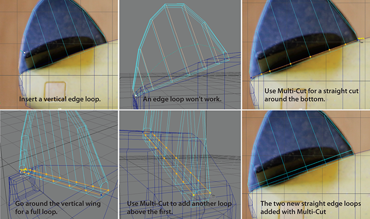
Figure 6-45: Insert a vertical edge loop (left) and then use Multi-Cut to insert a pair of horizontal edges that loop around (middle and right).
- Now you need to insert some edge loops to let you extrude the horizontal side wings that come out of the vertical wing to make an upside-down T for the stabilizers. If you use the Insert Edge Loop tool, the edge loops will be curved like the arch of the shape so far, as shown in Figure 6-45 (top middle). Instead, select the vertical wing object, and choose Mesh Tools ⇒ Multi-Cut.
In the side view panel, click to place the first vertex of the multi-cut as shown in Figure 6-45 (top right) and then click the opposite side of the vertical wing to insert edges across the bottom of the vertical wing, again as in Figure 6-45 (top right).
In the perspective panel, swing your view around so you can complete the multi-cut around to the other side of the vertical wing, clicking finally on the original yellow point where you started the multi-cut. The cursor will display the word close, as shown in Figure 6-45 (lower left).
- Use the tool again as in step 5 to place a parallel cut a little further up the vertical wing, as shown in Figure 6-45 (lower middle). Figure 6-45 (lower right) shows a side view of both added rows of edges inserted with the Multi-Cut tool.
- In Modeling Toolkit, enable Edge Selection (). In the persp view panel, if you double-click one of the upper edges on the vertical wing’s top arch, it will select an entire edge loop on the top arch of the wing shape. Do this twice to select the edge loops on both sides of the arch of the wing, as shown in Figure 6-46 (left).

Figure 6-46: Select these edges (left) and bevel them (right).
- Click the Bevel button in Modeling Toolkit and set Segments to 2 and Fraction to 0.85, as shown in Figure 6-46 (right). Press W to exit the tool.
- In the persp view panel, select the five faces shown at the base of the vertical wing where the side wings are. Make sure to select five on each side of the vertical wing, as shown in Figure 6-47.

Figure 6-47: Select these five faces on both sides of the vertical wing.
- In Modeling Toolkit, click Extrude and set Divisions to 3, Thickness to 1.5, and Offset to 0.03 for a slight taper at the end, as shown in Figure 6-48 (left). Press W for the Move tool and then use the top view to adjust vertices to loosely match the shape of these side wings for the stabilizers, as shown in Figure 6-48 (right). As you can see, the image used for reference is not centered well. But you should keep your geometry symmetrical, even though it won’t line up well on the right side of the plane in the image.
- Turn off the visibility of the bodyRefLayer in the Layer Editor. For the stabilizer wings, uncheck Enable Overrides in the Attribute Editor to show the wings in Shaded mode. Also, in the persp view’s panel menu bar, select Shading ⇒ Wireframe On Shaded to display wireframe on top of the shaded models.

Figure 6-48: Extrude the side wings (left) and shape them to create a nice shape, even though it won’t line up on one side (right).
- Select the outer loop of edges around the side wings, as shown in Figure 6-49 (left), and click Bevel in Modeling Toolkit with a Segments value of 2 and an Fraction value of 1.5, as shown in Figure 6-49 (right).
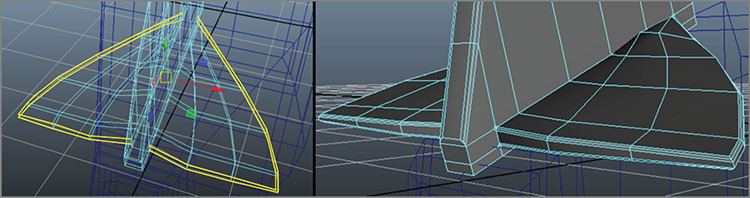
Figure 6-49: Select the edges around the side wings (left) and bevel them (right).
- At the front of the vertical wing, select the vertices shown in Figure 6-50 and scale them closer together in the X-axis to taper the front blade of that wing a bit. Select the tail wing object and call it tail.

Figure 6-50: Select these vertices and squeeze them together in the X-axis.
- Select the plane’s body geometry and uncheck Enable Overrides (in the Attribute Editor’s body tab under Display ⇒ Drawing Overrides) so you can see the entire plane in Shaded mode. Press 3 to see it in smooth preview. Press 1 to get out of smooth preview for the meshes.
Save your work! You can check your work against the scene file bodyModel_v03.ma in the Scenes folder of the Plane project.
You Spin Me Right Round—The Engine and Propeller
Now for the propeller! In the same scene as the body, you’ll create the engine and propellers at the front of the plane. Begin with your current scene, or use bodyModel_v03.ma. To begin with the engine, follow along here:
- In the Layer Editor, make sure the bodyRefLayer is visible and the R toggle is off so you can see and select the plane images. You need only the side reference image now, so select the other two image reference planes and press Ctrl+H to hide them. In the Outliner, their entries (bodyBottomRefPlane and bodyBackRefPlane) show up as gray. To unhide them, you would select them in the Outliner and press Shift+H. Leave them hidden for now.
- Select the body and press 3 for smooth preview.
- In the side view, create a CV curve to match the top half profile of the engine, as shown in Figure 6-51. You’ll use this curve to revolve a surface.

Figure 6-51: Draw a profile curve for the shape of the engine.
- In the persp view, select the profile curve and choose Display ⇒ NURBS ⇒ CVs to show the CVs of the curve. Click the Snap To Points icon in the status bar (
 ).
). - Press and hold D to engage the Pivot Move tool and move the pivot of the curve to snap to the bottom CV in the middle of the engine, as shown in Figure 6-52. This will ensure a good revolve. Turn off the point snap and then, with the curve selected, choose Display ⇒ NURBS ⇒ CVs to turn off the CVs on the curve.

Figure 6-52: Snap the pivot to the bottom CV.
- Then, with the curve selected, choose Surfaces ⇒ Revolve ❏. Set Axis preset to Z, Segments to 8, Output Geometry to Polygons, and Type to Quads; leave the Tessellation method on Standard Fit. Set the Chord Height ratio to 0.925 and the 3D delta to 0.10. Click Revolve to make the engine fit around the front of the plane, as shown in Figure 6-53.
- The engine may not be perfectly centered on the plane body, so move it to center it on the body. Then choose Edit ⇒ Delete By Type ⇒ History to erase the history on that shape. Select the profile curve and delete it. Select the engine geometry you just created and name it engine.

Figure 6-53: Revolve the curve to make the engine geometry.

Figure 6-54: Create this cylinder and place it in front of the engine.
Engine Detail
Now for some detail inside the engine.
- Choose Create ⇒ Polygon Primitives ⇒ Cylinder ❏ and set Axis Divisions to 16, Height Divisions to 11, and Cap Divisions to 1. Set Axis to Y and leave the rest at the defaults. Click Create and place the cylinder in front of the engine. Scale it to 0.125 in X and Z, and set the Y-axis scale to 0.4, as shown in Figure 6-54.

Figure 6-55: Select every other ring of faces (left) and extrude them (right).
- In Modeling Toolkit, enter Face Selection; in the side view, select every other ring of faces, as shown in Figure 6-55 (left). Click the Extrude button and enter a Thickness value of 0.03 and a Divisions value of 1, as shown in Figure 6-55 (right).
- Select the cylinder in Object mode, move it back into the engine, and place it as shown in Figure 6-56.

Figure 6-56: Place the cylinder into the engine.
- Turn on Snap To Points () and press and hold D to move the pivot. Snap the pivot point of the cylinder to the center of the engine, as shown in Figure 6-57.

Figure 6-57: Snap the pivot to the engine’s center.
- Choose Edit ⇒ Duplicate Special ❏. Set Rotate to 36 in the Z-axis and Number Of Copies to 9 and click Apply, as shown in Figure 6-58. This creates a ring of these cylinders inside the engine.

Figure 6-58: Create a ring of cylinders inside the engine.
The Propeller Blades
Follow these steps to create the propeller blades:
- Create a polygon cone. In the Channel Box, click polyCone1 and set Subdivisions Axis to 6 and Subdivisions Height to 3. Scale the cone to 0.72 in all three axes and rotate and place it against the inside of the engine. Select the sharp tip’s vertex and push it back to make the cone blunt, as shown in Figure 6-59.
- In the Modeling menu set, insert an edge loop toward the middle of the cone, as shown in Figure 6-60. Select every other of the new faces on the cone and click the Extrude button in Modeling Toolkit. Set Divisions to 1, Thickness to 3.2, and Offset to 0 to create the blades of the propeller, as shown in Figure 6-61. Click Extrude to turn off the tool.
- The blades sure do look weird; they are angled away from the engine. With the three faces at the ends of the blades still selected, move them back in the Y-axis to make them flush with the engine. The blades will go through the engine geometry a little bit, and that’s okay for now.
- On each of the three blades, insert an edge loop about where the blade intersects with the engine geometry, as shown in Figure 6-62 (left), and then scale the new edge loops to be much larger, as in Figure 6-62 (right).
- If you press 3 for smooth preview, the propellers look pretty good. Select them and move them out so the blades don’t penetrate the engine geometry.

Figure 6-59: Place a cone in the engine and shorten the tip to make it blunt.

Figure 6-60: Insert an edge loop.

Figure 6-61: Select every other face (left) and extrude them to create the propeller blades (right).
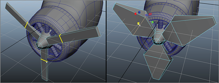
Figure 6-62: Insert an edge loop on each of the three blades (left) and then scale the new edge loops to be much bigger (right).
- Stay in smooth preview for the body (but not the engine; the engine will not need smoothing later) and work around the body of the plane. Move vertices on the body where it meets the engine to make sure that the body is not penetrating the engine.
Now you’re done with the body and need to move to the wings. Save your work and compare it to the scene file bodyModel_v04.ma in the Scenes folder of the Plane project. Note that this file has the plane body and propeller and stabilizer wings already set in smooth preview.
The Plane’s Wings
How can you fly without wings? Here you’ll create the wings in the existing plane body scene file and get them to attach to the body.
Modeling the Wing
Continue with your own model or use bodyModel_v04.ma to continue.
- Turn the visibility on for the bodyRefLayer. Then, in the Outliner, select the two hidden gray reference planes grouped under bodyRefPlanesGroup (click the plus sign to reveal them in the Outliner). Press Shift+H to unhide them in your view panels.
- Select all the parts of the plane you have made so far and press Ctrl+H to hide them.
- In the persp view, press 6 for Texture mode to see the reference image of the toy plane again. Create a cube and, in the Attribute Editor, in the pCube tab, check Enable Overrides under Display ⇒ Drawing Overrides. Turn off Shading as you’ve done before to make the cube display as wireframe. Using the top views, size and orient the cube to fit over the wing, as shown in Figure 6-63 (top). Since there is some perspective shift in the photos, the placements will be rough and will not line up in the side view at all, and that’s okay. Insert edge loops, as shown in Figure 6-63 (bottom), to create more segments.

Figure 6-63: Create a cube and place it as shown to start the left side of the wing (top). Insert the edge loops as shown (bottom).
- Now you’ll need to shape the wing. This time, let’s use a feature called Symmetry. In the top view, RMB+click the body and enter vertex mode. Then choose Modify ⇒ Transformation Tools ⇒ Move Tool ❏ (or double-click the Move tool icon (
 ) in the Tool Box).
 - In the option box, toward the bottom under the Symmetry Settings heading, click Symmetry and choose Object X from the pull-down menu. Now, any time you select vertices on one side of the wing, the opposite side’s vertices will be selected as well. This way you can shape one side of the wing, and the other side will shape itself to match.
- Use the top view to shape the left side of the wing, and as you do so, the right side will shape itself. Don’t worry if the shape of the wing does not match the image; remember that the image is not perfectly symmetrical. This is okay. Figure 6-64 shows the wing shaped using the Symmetry feature.
- In the front view and with Symmetry still on, shape the wing on the left to the image, as shown in Figure 6-65 (top).

Figure 6-64: Using Symmetry lets you shape one side of the wing and reflect that shape to the other side automatically.

Figure 6-65: Shape the vertices on one side, and Symmetry will shape the other side (top). Extrude the top face (middle). Then select and extrude the bottom end face (bottom).
- RMB+click the body and choose Faces for face selection mode. At the end of the wing on the left, select the top face at the very end. Symmetry will automatically select the other side’s top end face as well.
- Then in Modeling Toolkit, click the Extrude button. Set Divisions to 3, Thickness to 0.35, and Offset to 0.05. Both ends will extrude up, as shown in Figure 6-65 (middle).
- Select the bottom face at the end of the wing on the left side. Again, in Modeling Toolkit, click the Extrude button. Set Divisions to 2, Thickness to 0.15, and Offset to 0.05. This will extrude the ends of the wings, as shown in Figure 6-65 (bottom).
- In the Move tool options, turn off Symmetry. Turn off the display of the reference image layer (bodyRefLayer). From here on, you’ll shape the plane without the reference images. Select the top back edge that runs across the wing, as shown in Figure 6-66 (top), and move the edges down to taper the back of the wing down.
- Select the wing and in the Attribute Editor uncheck Enable Overrides to show the wing in Shaded mode again. Press 5 for Shaded mode in the persp view. Insert an edge loop two-thirds of the way up the side of the wing, as shown in Figure 6-66 (bottom). This will help retain the shape of the wing when you smooth the mesh later.

Figure 6-66: Select the topside back edges of the wing and move them down to taper the wing (top). Insert an edge loop two-thirds up the side of the wing (bottom).
- Open the option box for the Move tool (Modify ⇒ Transformation Tools ⇒ Move Tool ❏). Turn on Symmetry.
- RMB+click the wing and enter edge selection. Shape the tip of the wing as shown in Figure 6-67. Symmetry will take care of the opposite side. Then add an edge loop as shown. You will have to add an edge loop to the wing tip on the other side; Symmetry will not work with the Insert Edge Loop tool.
- Make any personal adjustments you’d like and press 3 to smooth preview the wing. Once you’re happy with the shape, press 1 to exit smooth preview and choose Mesh ⇒ Smooth ❏. Make sure the settings are at default in the option box by selecting Edit ⇒ Reset Settings and then click Smooth.

Figure 6-67: Shape the tip of the wing to curve it back a bit (left) and then add an edge loop at the wing tip for both sides of the wing (right).
- Orbit your camera to look at the underside of the wing. On the underside of the wing, select the faces, as shown in Figure 6-68. In Modeling Toolkit, click the Extrude button. Set Divisions to 2, Thickness to -0.16, and Offset to 0.10, as in Figure 6-68 (bottom).

Figure 6-68: Select these faces under the wing (top) and extrude to create indents in the wing’s underside (bottom).
- Now select the outer edges of those four new indents in the underside of the wing, as shown in Figure 6-69 (top). In Modeling Toolkit, bevel them with a Segments value of 2 and a Fraction value of 0.60, as shown in Figure 6-69 (bottom). Turn off Bevel. Save!

Figure 6-69: Select these edges (top) and bevel them (bottom).
Organizing the Scene and Smoothing the Geometry
Now let’s take a moment to clean up and organize the scene and smooth the rest of the geometry:
- Open the Outliner and select all the hidden objects that appear in gray text. Press Shift+H to unhide them. You should now see the plane, back stabilizer wings, and propellers in smooth preview.
- In the Outliner, select all the pCylinder objects you created inside the engine and press Ctrl+G to group them. Call the group insideEngine.
- Select the propeller and name it props. Select the wing and call it wings. Figure 6-70 shows the Outliner with the proper names.

Figure 6-70: The Outliner shows the organized scene.
- Select all the parts of the plane and press 1 to exit smooth preview for all the objects.
- Select the body, propellers, and tail wings, as shown in Figure 6-71 (top left), and choose Mesh ⇒ Smooth ❏. Check to make sure Add Divisions attribute is set to Exponentially, select Maya Catmull-Clark for Subdivision Type, and set Division Levels to 2, as shown in Figure 6-71 (right). Click Apply to smooth the plane, as shown in Figure 6-71 (bottom left).

Figure 6-71: The plane before smoothing (left) and after smoothing (right)
- Select all the geometry and choose Edit ⇒ Delete By Type ⇒ History to get rid of all the construction history.
- Since you don’t need the reference images anymore, delete the reference plane’s top group (bodyRefPlanesGroup). RMB+click the bodyRefLayer in the Layer Editor and select Delete Layer. And in the Hypershade (Windows ⇒ Rendering Editors ⇒ Hypershade), click Edit ⇒ Delete Unused Nodes. Save!
Adding the Wing Supports
Now you just need to connect the wings to the plane using the following steps:
- The wings sit a little low and penetrate the top of the plane’s body a little bit. Select the wing object and move it up to sit on top of the body. Rotate it a bit in the X-axis to align it with the angle of the top of the plane’s body better.
- Let’s smooth the wing a little more. With the wing selected, choose Mesh ⇒ Smooth, set Division Levels back to 1, and click Smooth. Select the smoothed wing and delete the history (Edit ⇒ Delete By Type ⇒ History).
- Now let’s make the support connecting the wing to the sides of the plane. Maximize the front view (press the spacebar). Choose Create ⇒ Curve Tools ⇒ CV Curve Tool and create a curve starting at the body of the plane up to the underside of the left-side wing, as shown in Figure 6-72.

Figure 6-72: Create this curve for the wing support.
- In the persp view’s menu, select Show and uncheck Polygons to turn off polygon view in the view panel. This shows you the curve you just made by itself. Select the curve and select Display ⇒ NURBS ⇒ CVs to show the CV points on the curve.

Figure 6-73: Create an oval shape and place it at the start of the curve.
- Next, create a circle (Create ⇒ NURBS Primitives ⇒ Circle). Scale it to a small oval and place it at the start of the CV curve line you just made, which is just inside the body of the plane. You can use Snap To Points to place the oval exactly at the start of the curve, as shown in Figure 6-73.
- In the persp view panel’s menu, click Show and check Polygons back on. Stay in wireframe view (press 4).
- Select the oval and the curve and select Surfaces ⇒ Extrude ❏. Set Style to Tube, Result Position to At Path, Output Geometry to Polygons, and Type to Quads; click Extrude, as shown in Figure 6-74. Press 5 to see it in Shaded mode and assess how you like it. You can adjust the shape or size of the oval as well as the shape of the CV curve line to customize the resulting support shape that connects the wing to the body.

Figure 6-74: Extrude to create the support for the wing.
- If you are happy with the shape of the support, select the original oval and the CV curve and delete them. Select the support arm geometry and name it supportArm in the Outliner.
- Now you need another for the other side of the plane. With supportArm selected, press Ctrl+D to duplicate it in place. In the Channel Box, enter an X-Scale value of -1.0 to create a mirror of the original arm. Since the pivot point of the original supportArm is in the center, scaling it in X-axis to -1 should place it perfectly on the other side of the plane.
- Move the arms a little toward the back of the plane so the part that meets the wing is centered on the wing, as shown in Figure 6-75.
- Select both support arms and choose Modify ⇒ Freeze Transformations. Name them wingSupport1 and wingSupport2.
- Select the wing supports and the wing itself, group them together, and call the group wingGroup. Move wingGroup a little closer to the front of the plane to line up the wing, as shown in Figure 6-76.

Figure 6-75: The support arms in place

Figure 6-76: Place the wing assembly.
- Select the insideEngine and wingGroup groups and all the other parts of the plane and group them together. Call the group planeGroup.
Save your work and compare it to the scene file bodyModel_v05.ma in the Scenes folder of the Plane project.
Assembling the Plane
You have all the parts finished, so let’s assemble the plane into a complete scene and make any finishing touches. In your current body model or the bodyModel_v05.ma scene, you just need to import the pontoons and you’re done.
- Choose File ⇒ Import. In the file dialog, on the right side, make sure Use Namespaces is checked. Navigate to the latest pontoon model you created or to the
pontoonModel_v04.mafile in the Scenes folder of the Plane project on the website. - A single pontoon will appear, unsmoothed, in the middle of the scene. In the Outliner, its name will be something like pontoonModel_v04:leftPontoonGroup. The name before the colon is the filename from which you imported the model. The part of the name on the right is the node name.
- Select the two pieces of geometry that make up the pontoon (not the top group) and choose Mesh ⇒ Smooth ❏. Set Division Levels to 1 and click Smooth.
- Select the top node of the newly smoothed pontoon assembly (pontoonModel_v04:leftPontoonGroup) and rename it to leftPontoonGroup in the Outliner. Then move it into place (as shown in Figure 6-77) and orient it properly by rotating it 180 degrees in the Y-axis.

Figure 6-77: Place the pontoon, duplicate it, and place the duplicate on the other side.
- Duplicate the pontoon group (leftPontoonGroup) by pressing Ctrl+D and set the copy’s X-axis scale to –1.0. Call the new group rightPontoonGroup and move it to the other side of the plane body. Figure 6-77 shows the proper placement for both pontoons.
- Select the geometry for both pontoons (not the top nodes) and choose Edit ⇒ Delete By Type ⇒ History.
- With the geometry still selected, choose Modify ⇒ Freeze Transformations.
- Using the Outliner, place both pontoon groups into the planeGroup by MMB+dragging them onto the planeGroup node.
- Now you’ll adjust how the pontoons look on the plane. In the Outliner, select the two top nodes of the pontoons. Select Deform ⇒ Lattice ❏. Set Divisions to 4, 3, 2 and click Create. This places a single lattice box around both the pontoons.
- You want to spread the pontoons to make a wider base for the plane. RMB+click the lattice itself and choose Lattice Point. Select the eight lattice points shown in Figure 6-78 (left) and move them away from the plane and up closer to the wing, as shown in Figure 6-78 (right).
- Repeat for the other pontoon’s lattice points to make the stance of the pontoons wider and closer to the wing. If your pontoon geometry is different from the one shown or the ones in the sample scene file
pontoonModel_v04.ma, you may need to adjust your lattice differently. You may also choose to skip this step because it’s a minor tweak. The proportions look nicer now! - Select the pontoon group nodes (Figure 6-79) and delete their history to get rid of the lattice (Edit ⇒ Delete By Type ⇒ History).
Figure 6-79 shows the completed plane and its hierarchy. You can check your work against the scene file bodyModel_v06.ma in the Scenes folder of the Plane project. In the following chapters, you will add textures and lighting to render the plane as a plastic bathtub toy.

Figure 6-78: Select these eight lattice points and move the pontoon away from the plane body and up closer to the wing (left).

Figure 6-79: The pontoons are adjusted, and the plane is ready to fly!
Summary
In this chapter, you flexed your knowledge from the previous chapters and concentrated on creating a model of a child’s bathtub toy airplane. You used many of the tools discussed in the previous chapters, from extruding to adding edge loops to using bevels.
Creating a model can be a lot of hard and sometimes tedious work, but when you start seeing it take shape, the excitement begins to build. From the basic shaping of the plane’s parts to the detail of assembling the plane, you worked hard in this chapter to create the toy plane.
You can take the procedures you used in this chapter to build your own toy design. The important lesson to take away from this chapter is how in depth you can get with a model and how a lengthy modeling process takes shape. Along the way, don’t forget to name your pieces and group everything in a sensible fashion.