
Chapter 5
Modeling with NURBS Surfaces and Deformers
NURBS is based on organic mathematics, which means you can create smooth curves and surfaces. NURBS models can be made of a single surface molded to fit, or they can be a collection of patches connected like a quilt. In any event, NURBS provides ample power for creating smooth surfaces for your models.
Now that you’ve learned the basics of creating and editing poly meshes, you’ll get into creating some organic surfaces using NURBS techniques. This chapter also explains how to use deformers to adjust a model, as opposed to editing the geometry directly as you did with the previous modeling methods.
- Learning Outcomes: In this chapter, you will be able to
- Use the surfacing techniques (Loft, Set Planar, and Revolve) to create surfaces
- Convert NURBS geometry into polygons
- Create polygon meshes directly from NURBS techniques
- Model a pair of glass candle holders and convert them to polygons
- Create CV curves and use Revolve to create a poly mesh
- Attach and detach curves
- Use the Sculpt Geometry tool to sculpt a mesh surface
- Use the Soft Deformation Modifier
- Use nonlinear deformers to adjust existing geometry
- Create edits to existing models using lattices
- Animate an object to deform through a lattice
NURBS for Organic Curves
NURBS is an acronym for Non-Uniform Rational B-Spline. That’s good to know for cocktail parties. NURBS modeling excels at creating curved shapes and lines, so it’s most often used for organic forms such as animals and people, as well as highly detailed cars. These organic shapes are typically created with a quilt of NURBS surfaces, called patches. Patch modeling can be powerful for creating complex shapes such as characters, but it can also be quite difficult and will not be covered in this book. I will, however, touch on the basics of NURBS surface modeling in this chapter.
In essence, Bézier curves are created with a starting and ending control vertex (CV) and usually two or more CVs in between that provide a smooth curvature. As each CV is laid down, the curve or spline tries to go from the previous CV to the next one in the smoothest possible manner.
As shown in Figure 5-1, CVs control the curvature. The hulls connect the CVs and are useful for selecting multiple rows of CVs at a time. The starting CV appears in the Autodesk® Maya® software as a closed box. The second CV, which defines the curve’s direction, is an open box, so you can easily see the direction in which a curve has been created. The curve ends, of course, on the endpoint CV. The start and end CVs are the only CVs that are always actually on the curve itself.

Figure 5-1: A Bézier curve and its components
NURBS Modeling
NURBS surfaces are defined by curves called isoparms, which are created with CVs. The surface is created between these isoparms to form spans that follow the surface curvature defined by the isoparms, as in Figure 5-2. The more spans, the greater the detail and control over the surface.

Figure 5-2: NURBS surfaces are created between isoparms. You can sculpt them by moving their CVs.
It’s easier to get a smooth deformation on a NURBS surface with few CVs than on a polygon. Achieving the same smooth look on a polygon would take much more surface detail. As you can see in Figure 5-3, NURBS modeling yields a smoother deformation, whereas polygons can become jagged at the edges.

Figure 5-3: A NURBS cylinder (left) and a polygonal cylinder (right) bent into a C shape. The NURBS cylinder remains smooth, and the polygon cylinder shows its edges.
You can convert NURBS to polygons at any time, but converting polygons back to NURBS can be tricky.
- Try This Open a new scene (choose File ⇒ New Scene). In the new scene, you’ll create a few curves on the ground plane grid in the perspective (persp) panel. Maximize the perspective view by moving your cursor to it and pressing the spacebar. Choose Create ⇒ Curve Tools ⇒ CV Curve Tool. Your cursor turns into a cross. Lay down a series of points to define a curved line on the grid. Notice how the Bézier curve is created between the CVs as they’re laid down.
NURBS surfaces are created by connecting (or spanning) curves. Typical NURBS modeling pipelines first involve creating curves that define the edges, outline, paths, and/or boundaries of surfaces.
A surface’s shape is defined by its isoparms. These surface curves, or curves that reside solely on a surface, show the outline of a shape much as the chicken wire does in a wire mesh sculpture. CVs on the isoparms define and govern the shape of these isoparms just as they would regular curves. Adjusting a NURBS surface involves manipulating the CVs of the object.
Levels of Detail
NURBS is a type of surface in Maya that lets you adjust its detail level at any time to become more or less defined as needed. Pressing 1, 2, or 3 toggles between detail levels for any selected NURBS object from low quality at 1 to high quality at 3.
NURBS Surfacing Techniques
The easiest way to create a NURBS surface is to create a NURBS primitive, and then you can sculpt the primitive surface by moving its CVs. But you can also make surfaces in several ways without using a primitive. All these methods involve using NURBS curves to define a boundary, shape, or path of the surface and then using one of the methods described in the following sections to create the surfaces.
Lofting
The most common surfacing method is lofting, which takes at least two curves and creates a surface span between each selected curve in the order in which they’re selected. Figure 5-4 shows the result of lofting a few curves together.
To create the loft in Figure 5-4, follow these steps:
- Switch to the Modeling menu set (press F2).
- Draw the two curves.
- Select the curves in the order in which you want the surface to be generated.
- Choose Surfaces ⇒ Loft, or click the Loft icon in the Curves/Surfaces shelf (
 ).
).
When you define more curves for the loft, Maya can create more complex shapes. The more CVs for each curve, the more isoparms you have and the more detail in the surface. Lofting works best when curves are drawn as cross-sectional slices of the object to be modeled.
Lofting is used to make a variety of surfaces, which may be as simple as tabletops or as complex as human faces.
Revolved Surface
A revolved surface requires only one curve that is turned around a point in space to create a surface, like a woodworker shaping a table leg on a lathe. First you draw a profile curve to create a profile of the desired object, and then you revolve this curve (anywhere from 0 degrees to 360 degrees) around a single point in the scene to sweep a surface.
The profile revolves around the object’s pivot point, which is typically placed at the origin but can be easily moved. Figure 5-5 (left) shows the profile curve for a wine glass. The curve is then revolved around the Y-axis a full 360 degrees to create the wine glass. Figure 5-5 (right) is the complete revolved surface with the profile revolved around the Y-axis.

Figure 5-5: A profile curve is drawn in the outline of a wine glass in the Y-axis (left image) and the revolved surface (right image).

Figure 5-4: A loft created with four curves that are selected in order from left to right
To create a revolved surface, draw and select your profile curve and then choose Surfaces ⇒ Revolve.
A revolved surface is useful for creating objects such as bottles, furniture legs, and baseball bats—anything that is symmetrical around an axis.
Extruded Surface
An extruded surface uses two curves: a profile curve and a path curve. First you draw the profile curve to create the profile shape of the desired surface. Then you sweep the curve from one end of the path curve to its other end, creating spans of a surface along its travel. The higher the CV count on each curve, the more detail the surface will have. An extruded surface can also take the profile curve and simply stretch it to a specified distance straight along one direction or axis, doing away with the profile curve. Figure 5-6 shows the profile and path curves, and Figure 5-7 shows the resulting surface after the profile is extruded along the path.

Figure 5-6: The profile curve is drawn in the shape of an I, and the path curve comes up and bends toward the camera.

Figure 5-7: After extrusion, the surface becomes a bent I-beam.
To create an extruded surface, follow these steps:
- Draw both curves.
- Select the profile curve.
- Shift+click the path curve.
- Choose Surfaces ⇒ Extrude.
An extruded surface is used to make items such as winding tunnels, coiled garden hoses, springs, and curtains.
Planar Surface
A planar surface uses one perfectly flat curve to make a two-dimensional cap in the shape of that curve. You do this by laying down a NURBS plane (a flat, square NURBS primitive) and carving out the shape of the curve like a cookie cutter. The resulting surface is a perfectly flat, cutout shape.
To create a planar surface, draw and select the curve and then choose Surfaces ⇒ Planar.
You can also use multiple curves within each other to create a planar surface with holes in it. A simple planar surface is shown on the left side of Figure 5-8. When a second curve is added inside the original curve and both are selected, the planar surface is created with a hole. On the right side is the result when the outer curve is selected first and then the inner curve is selected before choosing Surfaces ⇒ Planar.

Figure 5-8: A planar surface based on a single curve (left); a planar surface based on a curve within a curve to create the cutout (right)
A planar surface is great for flat lettering, for pieces of a marionette doll or paper cutout, or for capping the ends of a hollow extrusion. It’s usually best to create the planar surface as a polygon mesh, a technique you’ll see later in this chapter in the “Using NURBS Surfacing to Create Polygons” section.
Beveled Surface
With the Bevel Surface function you take an open or closed curve and extrude its outline to create a side surface. It creates a bevel on one or both corners of the resulting surface to create an edge that can be made smooth or sharp (see Figure 5-9). The many options in the Bevel tool allow you to control the size of the bevel and depth of extrusion, giving you great flexibility. When a bevel is created, you can easily cap the bevel with planar surfaces.
To create a bevel, draw and select your curve and then choose Surfaces ⇒ Bevel.
Maya also offers a Bevel Plus surface, which has more creation options for advanced bevels. A beveled surface is great for creating 3D lettering, for creating items such as bottle caps or buttons, and for rounding out an object’s edges.

Figure 5-9: A curve before and after it’s beveled. The beveled surface has been given a planar cap.
Boundary Surface
A boundary surface is so named because it’s created within the boundaries of three or four surrounding curves. For example, you draw two vertical curves opposite each other to define the two side edges of the surface. Then you draw two horizontal curves to define the upper and lower edges. These curves can have depth; they need not be flat for the boundary surface to work, unlike a planar surface. Although you can select the curves in any order, it’s best to select them in opposing pairs. In Figure 5-10, four curves are created and arranged to form the edges of a surface. First, you would select the vertical pair of curves because they’re opposing pairs; then, you would select the second two horizontal curves before choosing Surfaces ⇒ Boundary.
A boundary surface is useful for creating shapes such as car hoods, fenders, and other formed panels, especially when created as polygon mesh.
Using NURBS Surfacing to Create Polygons
You can easily create swatches of polygon surfaces instead of NURBS surfaces by using any of these NURBS surfacing tools. To create a polygonal surface instead of a NURBS surface, open the option box for any particular NURBS tool.
- Try This Draw two CV curves as you did at the beginning of this chapter, both with the same number of CVs. Choose Surfaces ⇒ Loft ❏ and click the Polygons option for Output Geometry. Set Type to Quads and leave the Tessellation method as Standard fit. Set the Chord height ratio to 0.95 and the 3D delta to 0.07, as shown in Figure 5-11. Click Apply.

Figure 5-10: Four curves arranged to create the edges for a surface (left); the resulting boundary surface formed from the four curves (right)

Figure 5-11: Create two curves and loft between them to make a polygon mesh.
The creation options that appear at the bottom of the option window affect the tessellation of the resulting surface; that is, you use them to specify the level of detail and the number of faces with which the surface is created.
The Standard Fit Tessellation method uses the fewest faces to create the surface without compromising overall integrity. The sliders adjust the resulting number of faces in order to fit the finer curvature of the input curves, particularly Chord Height Ratio and 3D delta.
The Chord Height Ratio determines the amount of curve in a particular region and calculates how many more faces to use to give an adequate representation of that curved area with polygons. Values approaching 1.0 create more faces and better detail with surfaces that have multiple or very intense curves. Lower 3D Delta values will fit smaller faces around tight curves and lower the Fractional Tolerance settings, giving you a smoother surface and a greater number of faces.
Construction History
History has to do with how objects react to change. Leaving History on when creating objects allows you to adjust the original parameters that created that object. For example, the loft you just created will update whenever the curves you used to create the loft move or change shape.
- Try This Select the new poly surface you just lofted in the previous “Try This” and open the Attribute Editor. Select the nurbsTessellate1 tab and open the Advanced Tessellation Options heading. In the Standard Fit Options heading, experiment with changing the Chord Height Ratio and Delta values to see how the poly surface re-creates itself.
- Also try selecting the CVs of the original curves (RMB+click one of the two curves you made and select Control Vertex from the marking menu). Adjust the curve, and the surface will re-create itself because of surface history.
In the status line, the History icon (![]() ) toggles History on and off. Why wouldn’t you want History turned on for everything? After a long day of modeling, having History on for every single object can slow down your scene file, adding unnecessary bloat to your workflow. But it isn’t typically a problem on most surface types unless the scene is huge, so you should leave it on while you’re still modeling.
) toggles History on and off. Why wouldn’t you want History turned on for everything? After a long day of modeling, having History on for every single object can slow down your scene file, adding unnecessary bloat to your workflow. But it isn’t typically a problem on most surface types unless the scene is huge, so you should leave it on while you’re still modeling.
If you no longer want a surface or an object to retain its History, you can selectively delete it from the surface. Select the surface and choose Edit ⇒ Delete By Type ⇒ History. You can also rid the entire scene of History by choosing Edit ⇒ Delete All By Type ⇒ History. Just don’t get them mixed up!
Other Tessellation Methods
Standard Fit will probably do the best job in most situations; however, here are the other tessellation methods you can use:
- The General Tessellation method creates a specific number of lines, evenly dividing the horizontal (U) and vertical (V) into rows of polygon faces.
- The Control Points method tessellates the surface according to the number of points on the input curves. As the number of CVs and spans on the curves increase, so does the number of divisions of polygons.
- The Count method simply relies on how many faces you tell it to make—the higher the count, the higher the tessellation on the surface. Experiment with the options to get the best poly surface results.
Converting a NURBS Model to Polygons
Some people prefer to model on NURBS curves and either create poly surfaces or convert to polygons after the entire model is done with NURBS surfaces. Ultimately, you’ll find your own workflow preference, but it helps greatly if you’re comfortable using all surfacing methods. In the following section, you’ll convert a NURBS model to polygons.
- Try This Convert a NURBS-modeled axe into a poly model like one that might be needed in a game.
Open axe_model_v1.mb in the Scenes folder of the Axe project from the companion web page. The toughest part of this simple process is getting the poly model to follow all the curves in the axe with fidelity, so you’ll have to convert parts of the axe differently. Follow these steps:
- Grab the handle and choose Modify ⇒ Convert ⇒ NURBS To Polygons ❏. Use the default presets. If need be, reestablish your settings by choosing Edit ⇒ Reset Settings; the handle converts well to polygons. Click Apply, and a poly version of the axe handle appears on top of the NURBS version. Move it eight units to the right to get it out of the way. You’ll move the other parts eight units as well to assemble the poly axe properly.
- Select the back part of the axe head. All those surfaces are grouped together to make selection easy. The default settings will work for this part as well, so click Apply and move the resulting model eight units to the left.
- The front of the axe head holds a lot of different arcs, so you’ll have to create it with finer controls. Change Fractional Tolerance from 0.01 to 0.0005. This yields more polygons but finer-curved surfaces. Figure 5-12 shows the result.

Figure 5-12: A faithful high-poly conversion (on the right) of a NURBS axe (on the left)
Using Artisan to Sculpt NURBS
Imagine that you can create a NURBS surface and sculpt it using your cursor the way hands mold the surface of wet clay. As you saw with the Sculpt Geometry tool in Chapter 4, you can push and pull vertices easily by virtually painting on the surface. You can sculpt NURBS surfaces much the same way by accessing Surfaces ⇒ Sculpt Geometry Tool ❏.
If you plan to sculpt a more detailed surface, be sure to create the surface with plenty of surface spans and sections. You’ll try this tool a little bit in the next section.
Creating a Pair of Glass Candle Holders
Let’s put some of this information to good use and build a pair of glass candle jars. You will use these glass jars in Chapters 7, 10, and 11 to create shaders (materials), light them, and render them. Copy the project folder candleHolder from the book’s companion web page, www.sybex.com/go/introducingmaya2016, and set your project to it.
Creating the Objects
You’ll start with a profile curve for a Revolve surface:

Figure 5-13: Start with the first four CVs, and then work clockwise to complete your curve to match this shape.
- Click Create ⇒ Curve Tools ⇒ CV Curve tool and turn on grid snaps (
 ) in the status bar.
 - In the front view panel, click the origin to snap the first CV to (0,0,0). Snap the second and third CVs to the grid points on the left. Click the fourth CV slightly higher than the third CV to create a sharp curve. Figure 5-13 marks the first four CVs.
Continue laying down CVs to match the shape shown in Figure 5-13. This will be the profile curve for the body of the jar.
- In the Modeling menu set, select Surfaces ⇒ Revolve ❏. Make sure Axis Preset is Y and set Output Geometry to Polygons. Set Type to Quads. To get smooth curves in the mesh, increase Chord Height Ratio to 0.97 or use 0.935 for a less dense model instead. (See the “Making Less Dense Candle Geometry” sidebar for more information.) Lower 3D Delta to 0.06. Click Revolve to make the jar’s body (Figure 5-14).

Figure 5-14: Revolve the surface with these settings.
- Now for the lid. In the front view panel, click the Show menu in the view panel’s menu bar and toggle off Polygons, as shown in Figure 5-15. This will disable polygon display in the front view panel to make it easy to work on the next profile curve for the lid.

Figure 5-15: Turn off polygons in the front view panel.
- The lid will have two parts: the main glass lid and a plastic stopper that goes around the bottom of the glass part where it inserts into the jar. Create a curve to match Figure 5-16. Notice where the first few CVs are created and follow counterclockwise to lay down all the CVs as shown.
- Now let’s make a profile curve for the plastic sealer that goes around the base of the lid. In the front view panel, create another curve to match the shape in Figure 5-17.
- Now, the plastic sealer is open ended, so you need to close that curve to get a solid geometry when you revolve it. In Object mode, select the curve and choose Curves ⇒ Open/Close. The end will close, but it will elongate. Select the end CVs and move them back to line up with the glass lid, as shown in Figure 5-18.
- Now for the fun part! Go into the persp view panel, select the plastic sealer’s profile curve, and choose Surfaces ⇒ Revolve just as you did last time, with the same settings originally shown in step 3 and Figure 5-14. Figure 5-19 (left) shows the plastic sealer.

Figure 5-16: Start with the first CVs shown and follow the line counterclockwise to create this profile for the glass lid.

Figure 5-17: Profile curve for the plastic sealer for the lid

Figure 5-18: Close the curve and adjust the CVs to reshape the profile for the plastic stopper.
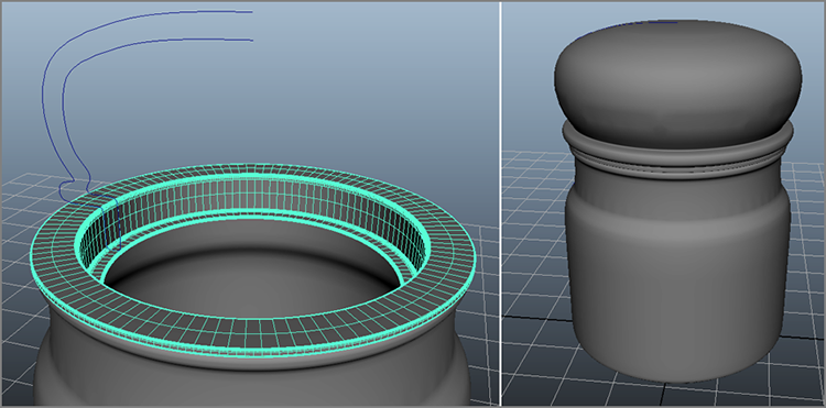
Figure 5-19: The plastic sealer (left) and the completed jar (right)

Figure 5-20: Selecting a point on Curve
- What’s a candle jar without a candle? You need the candle in the jar to form right up against the glass, so you’ll use part of the same profile curve you used for the jar. Select the original jar body profile curve, and in the Outliner, change its name to glassProfile. With it still selected, choose Edit ⇒ Duplicate (or press Ctrl+D to copy the curve). Rename that curve from glassProfile to candleProfile.
- Select the glassProfile curve again and press Ctrl+H to hide it from view. Its entry in the Outliner will turn gray. RMB+click the duplicated curve (candleProfile) and select Curve Point from the marking menu. Click the curve and drag the little red point that appears on the curve up the inside wall to right below where it begins to curve in, as shown in Figure 5-20. Release the mouse, and the point turns yellow. You are going to break the curve at this point.
- Choose Curves ⇒ Detach to cut the curve at that point. The top of the curve should be green now and the bottom white. Select just the top part of the curve and press Delete to delete it. Figure 5-21 (left) shows the remaining curve you’ll use to create the candle.
- Draw a straight line curve as shown in the front view panel to match Figure 5-21 (right). It’s okay if the first CV isn’t exactly on the candle’s profile curve; close is good enough.
- Now select both the straight line curve and the candleProfile curve and choose Curves ⇒ Attach ❏. Set Attach Method to Connect, set Multiple Knots to Remove, and uncheck Keep Originals, as shown in Figure 5-22. Click Attach, and the two curves will connect as shown to make the candle’s profile curve.
- With that candle curve selected, choose Surfaces ⇒ Revolve with the same settings as in step 3 to create the candle.

Figure 5-21: The candle’s profile curve

Figure 5-22: Attach the curves to complete the candle’s profile.
You can edit the shape of any of these curves you’ve created, and because of History, the surfaces you created with Revolve will adjust to match the new profiles. To turn the glass profile curve (glassProfile) back on, select it in the Outliner and press Shift+H. You can easily edit the shape of the object to your liking now. Once you are done, simply delete the profile curves if you don’t need them anymore.

Figure 5-23: The final candle’s hierarchy
Once you delete the profile curves, name the objects. Group the lid objects together (name it jarLid) and group the glass jar and candle together (name it jarCandle), as shown in Figure 5-23. Finally, in the front view panel, select Show ⇒ Polygons (in the view panel’s menu bar) to turn on the display of polygons in that view panel.
You can find the candle jar in candleModel_v01.mb in the scenes folder of the candleHolder project. This file still retains the original profile curves for you. candleModel_v02.mb has the completed jar without the original profile curves and with the objects properly named and grouped. This file uses the smoother geometry called for in step 3 (with a Chord Height Ratio value of 0.97) and therefore is also a larger file than if you created the jar with a lower Chord Height Ratio value.
Detailing the Objects
Now let’s add a little detail to the candle inside the jar using the Sculpt geometry tool. Continue with your own file, or open candleModel_v02.mb in the scenes folder of the candleHolder project.
- Select the outer glass jar and press Ctrl+H to hide it. In the Outliner, select the jarLid group and press Ctrl+H to hide the lid and plastic sealer, too.
- In the Modeling menu set, choose Mesh Tools ⇒ Sculpting Tools ⇒ Sculpt Tool ❏. It’s especially important to open the option box for this tool.
In the Sculpt Tool options, set Brush Size to 0.25. Your cursor changes to the Artisan brush, a gray circle, as shown in Figure 5-24.
- If you click the candle with the brush, it will push in the geometry quite a bit. Undo anything you may have done with this tool. If the geometry pulls out instead of pushing in, turn on the Invert check box in the tool options. In the options, set Strength to 0.2, this will limit the amount of influence each brush stroke will have on moving the geometry. This ensures that the sculpting is layered slowly; each successive brush stroke will push the geometry slowly further. Feel free to reduce the Strength value for more finesse in your sculpting. You could also adjust the Buildup value to 3.0 instead of adjusting Strength. This attribute controls the maximum amount you affect the geometry with each stroke. Adjusting Strength, however, allows for more finesse.

Figure 5-24: The Sculpt tool lets you mold your surface by painting on it. Here, the brush is set to push in the surface of the sphere as you paint.
Sculpt the top of the candle slightly to create an uneven surface. Figure 5-24 shows the resulting uneven candle top. Try not to sculpt the sides of the candle; this may cause the sides to bulge out and then penetrate the glass jar. Try working only on the top of the candle for a melted look.
- In the options, toggle on the Invert setting to allow the Sculpt tool to pull up the geometry. Slowly raise the middle top of the candle to create a place for the wick, as shown in Figure 5-25.

Figure 5-25: Raise the top center a little for a place to put the candle’s wick.
- Press W to exit the Sculpt tool and then close Tool Options. With Interactive Creation turned off, create a polygon cylinder with Height Divisions of 8 and Cap Divisions of 4. Scale and place the cylinder to be the wick of the candle, as shown in Figure 5-26 (left).
- Select vertices and move and rotate them around to give the cylinder a more interesting shape. Then use the Sculpt tool to misshape the cylinder as if the wick has already been burned, as shown in Figure 5-26 (right). Press 3 to see a smooth preview of the wick as you work.

Figure 5-26: Place a cylinder as the candle’s wick (left) and use the Sculpt tool and manual vertex manipulation to shape it into an already burned wick as shown (right).
- Once you are happy with the wick, smooth the wick’s geometry by choosing Mesh ⇒ Smooth ❏. Set Division Levels to 1 and click Smooth.
- Select the wick and erase the history on it by choosing Edit ⇒ Delete By Type ⇒ History. Name the object wick and place it into the jarCandle group, as shown in Figure 5-27.
Figure 5-27: Group the wick into the hierarchy.
- In the Outliner, select the jarLid group and press Shift+H to unhide it. Also select the glassJar object (under the jarCandle group) to unhide that as well. Then group both jarLid and jarCandle groups together into a new group called candleGroup.
You can check your work against the file candleModel_v02.mb in the scenes folder of the candleHolder project. With the glass candle jar holder complete, you’ll be able to use it later to create a glass and candle wax shader in Chapter 7 and then render the object with reflections and refractions in Chapter 11. Nice job! Go grab a cookie.
Modeling with Simple Deformers
In many ways, deformers are the Swiss Army knives of Maya animation, except that you can’t open a bottle with them. Deformers are handy for creating and editing modeled shapes in Maya. These tools allow you to change the shape of an object easily. Rather than using CVs or vertices to distort or bend an object manually, you can use a deformer to affect the entire object. Popular deformers, such as Bend and Flare, can be powerful tools for adjusting your models quickly and evenly, as you’re about to see.
Nonlinear deformers, such as Bend and Flare, create simple shape adjustments for the attached geometry, such as bending the object. You can also use deformers in animation to create effects or deformations in your objects. You’ll explore this later in the book.
Using the Soft Modification Deformer
First, let’s try using the Soft Modification tool. Choose Modify ⇒ Transformation Tools ⇒ Soft Modification Tool, and its icon (![]() ) appears below the Tool Box. This tool allows you to select an area on a surface or model and make any adjustments in an interesting way. These adjustments taper off away from the initial place of selection, giving you an easy way to soft-modify an area of a model, much like lifting up a tablecloth from the middle.
) appears below the Tool Box. This tool allows you to select an area on a surface or model and make any adjustments in an interesting way. These adjustments taper off away from the initial place of selection, giving you an easy way to soft-modify an area of a model, much like lifting up a tablecloth from the middle.
To try the Soft Modification tool, follow these steps:
- In a new scene create a Polygon plane by choosing Create ⇒ Polygon Primitives ⇒ Plane ❏. Set both the Width Divisions and Height Divisions sliders to 10 and click Create.
- Click and drag a plane on the grid if Interactive Creation is turned on; otherwise, a plane appears at the origin on your grid. Select the Scale tool and scale the plane up to about the size of the grid.

Figure 5-28: Creating and manipulating a soft modification
- Select Modify ⇒ Transformation Tools ⇒ Soft Modification Tool and click the plane somewhere just off the middle. Doing so creates an S and a special manipulator to allow you to move, rotate, or scale this soft selection (see Figure 5-28). You also see a yellow-to-red-to-black gradient around the S manipulator. This shows you the area and degree of influence, where yellow moves the most and black the least.
- Grab the cone handle and drag it up to move the soft selection up. Notice that the plane lifts up in that area only, gradually falling off.
- Grabbing the cube handle scales the soft selection, and dragging the circle rotates it. After you’ve finished making your soft adjustments, make sure to press W for the Move tool and to exit the Soft Modification tool. Otherwise, you will create new soft modification handles every time you click the mesh.
You can go back to any soft selection by selecting the S on the surface for later editing. You can place as many soft selections as you need on a surface. Figure 5-29 shows the soft modification adjusting the plane.

Figure 5-29: Lifting an area of the Polygon plane
Modeling Using the Bend Deformer
Let’s apply a deformer. In a new Maya scene, you’ll create a polygonal cylinder and bend it to get a quick idea of how deformers work. Follow these steps:
- Choose Create ⇒ Polygon Primitives and turn on Interactive Creation. Then, choose Create ⇒ Polygon Primitives ⇒ Cylinder. Click and drag to create the base. Make it a few units in diameter; the exact sizing isn’t important here. Click and drag to make the height of the cylinder 7 or 8 units. Make sure your create options are set to the defaults so that they’re consistent with these directions.
- With the cylinder selected, make sure you’re still in the Modeling menu set and choose Deform ⇒ Nonlinear ⇒ Bend, under the Create section. Your cylinder turns magenta if you are in wireframe display mode, and a thin line appears at the center of the cylinder, running lengthwise. Figure 5-30 shows the deformer and its Channel Box attributes. Depending on your settings, your deformer may be created in a different axis than the one pictured. You can reset the deformer’s options as needed. Click bend1 in the Channel Box to expand the deformer’s attributes as shown in the figure.
- Click Curvature and enter a value of 60. Notice that the cylinder takes on an odd shape, as shown in Figure 5-31. The Bend deformer itself is bending nicely, but the geometry isn’t. Also, the geometry is offset and weird-looking because there aren’t enough divisions in the geometry to allow for a proper bend.
- Select the cylinder, and click polyCylinder1 in the Channel Box to expand the shape node’s attributes. Enter a value of 12 for the Subdivisions Height attribute (see Figure 5-32), and your cylinder will bend with the deformer properly, as shown in Figure 5-33.

Figure 5-30: Creating the Bend deformer

Figure 5-31: Notice the problem with this cylinder?

Figure 5-32: Increase Subdivisions Height to 12.

Figure 5-33: The cylinder bends properly now that it has the right number of divisions.
- Try adjusting the Bend deformer’s Low Bound and High Bound attributes. This allows you to bend one part of the cylinder without affecting the other. For example, set the Bend deformer’s High Bound option to 0.25 instead of 1. This causes the top half of the cylinder to bend only one-quarter of the way up and continue straight from there.
Experiment with moving the Bend deformer and seeing how doing so affects the geometry of the cylinder. The deformer’s position plays an important role in how it shapes an object’s geometry.
Adjusting an Existing Axe Model
In this exercise, you’ll take a NURBS model of an axe and fine-tune the back end of the axe head. In the existing model, the back end of the axe head is blunt, as you can see in Figure 5-34. You’ll need to sharpen the blunt end with a nonlinear deformer. Open the AxeHead_v01.ma file in the scenes folder of the Axe project from the companion web page, and follow these steps:
- Select the top group of the axe head’s back end. To do so, open the Outliner and select
axeHead_Back(see Figure 5-35).

Figure 5-34: The axe head is blunt.

Figure 5-35: Select the back of the axe head.
- Press F4 to switch to the Modeling menu set, if you’re not already.
- Create a Flare deformer by choosing Deform ⇒ Nonlinear ⇒ Flare, under the Create section. The Flare deformer appears as a cylindrical object (see Figure 5-36).
- Rotate the deformer 90 degrees in the Z-axis, as shown in Figure 5-37.
- Open the Attribute Editor (Ctrl+A), click the flare1 tab to access the Flare controls, and enter the following values:
| Attribute | Value |
| Start Flare Z | 0.020 |
| High Bound | 0.50 |
These values taper in the end of that part of the axe head, as shown in Figure 5-38. This is a much easier way of sharpening the blunt end than adjusting the individual CVs of the NURBS surfaces.

Figure 5-36: The Flare deformer appears as a cylinder.

Figure 5-37: Rotate the deformer 90 degrees in the Z-axis.

Figure 5-38: Sharpen the axe’s back edge.
Deformers use History to distort the geometry to which they’re attached. You can animate any of the attributes that control the deformer shapes, but in this case you’re using the deformer as a means to adjust a model. When you get the desired shape, you can discard the deformer. However, simply selecting and deleting the deformer will reset the geometry to its original blunt shape. You need to pick the axeHead_Back geometry group (not the deformer) and delete its History by choosing Edit ⇒ Delete By Type ⇒ History.
The Lattice Deformer
When a model requires more intricate editing with a deformer, you’ll need to use a lattice. A lattice is a scaffold that fits around your geometry. The lattice object controls the shape of the geometry. When a lattice point is moved, the lattice smoothly deforms the underlying geometry. The more lattice points, the greater control you have. The more divisions the geometry has, the more smoothly the geometry will deform.
Lattices are especially useful when you need to edit a relatively complex poly mesh or NURBS surface that is too dense to edit efficiently directly with CVs or vertices. With a lattice, you don’t have to move the individual surface points.
Lattices can work on any surface type, and a single lattice can affect multiple surfaces simultaneously. You can also move an object through a lattice (or vice versa) to animate a deformation effect, such as a golf ball sliding through a garden hose.
Creating an Alien Hand
Make sure you’re in the Modeling menu set. To adjust an existing model or surface, select the models or applicable groups to deform, and choose Deform ⇒ Lattice, under the Create section. Figure 5-39 shows a polygonal hand model with a default lattice applied. The top node of the hand has been selected and the lattice applied.

Figure 5-39: A lattice is applied to the polygonal hand model.
Your objective is to create an alien hand by thinning and elongating the hand and each of the fingers—we all know aliens have long, gawky fingers! Because it would take a lot of time and effort to achieve this by moving the vertices of the poly mesh itself, using lattices here is ideal.
To elongate and thin the entire hand, load the scene file detailed_poly_hand.ma from the Poly_Hand project from the companion web page, and follow these steps:
- Select the top node of the hand (
poly_hand) in the Outliner and choose Deform ⇒ Lattice, under the Create section. Doing so creates a default lattice that affects the entire hand, fingernails and all. Although you can change the lattice settings in the option box upon creation, you’ll edit the lattice after it’s applied to the hand. - The lattice is selected after it’s created. Open the Attribute Editor and click the ffd1LatticeShape tab. The three attributes of interest here are S Divisions, T Divisions, and U Divisions. These sliders control how many divisions the lattice uses to deform its geometry. Set S Divisions to 3, T Divisions to 2, and U Divisions to 3 for the result shown in Figure 5-40.

Figure 5-40: Changing the number of divisions in the lattice
- With the lattice selected, press F8 to switch to Component mode and display the lattice’s points. You’ll use these points to change the overall shape of the hand. Select the lattice points on the thumb side of the hand and move them to squeeze in that half of the hand. Notice how only that zone of the model is affected by that part of the lattice.
- Toggle back to Object mode (press F8 again) and scale the entire lattice to be thinner in the Z-axis and longer in the X-axis. The entire hand is deformed in accordance with how the lattice is scaled (see Figure 5-41).

Figure 5-41: Lengthen the hand using the deformer.
Now that you’ve altered the hand, you have no need for this lattice. If you delete the lattice, the hand will snap back to its original shape. You need to delete the construction history on the hand to get rid of the lattice, as you did with the axe head exercise earlier in this chapter.
- Select the top node of the hand and choose Edit ⇒ Delete By Type ⇒ History.
Creating Alien Fingers
The next step is to elongate the individual fingers and widen the knuckles. Let’s begin with the index finger. Follow these steps:
- Select the top node of the hand and create a new lattice as before. It forms around the entire hand.

Figure 5-42: Select the lattice and base nodes.
Although you can divide the lattice so that its divisions line up with the fingers, it’s much easier and more interactive to scale and position the entire lattice so it fits around the index finger only.
Simply moving and scaling the selected lattice will deform the hand geometry. You don’t want to do this. Instead, you need to select the lattice and its base node. This lets you change the lattice without affecting the hand.
- In the Outliner, select both the ffd1Lattice and ffd1Base nodes (see Figure 5-42).
- Scale, rotate, and transform the lattice to fit around the index finger, as shown in Figure 5-43.

Figure 5-43: Position the lattice and its base to fit around the index finger.
- Deselect the base, and set the lattice S Divisions to 7, T Divisions to 2, and U Divisions to 3.
- Adjust the lattice to lengthen the finger by pulling the lattice points (see Figure 5-44). Pick the lattice points around each of the knuckles individually and scale them sideways to widen them.
- To delete the lattice and keep the changes to the finger, select the top node of the hand and delete its History.

Figure 5-44: Flare out the knuckles.
- Repeat this entire procedure for the rest of the fingers to finish your alien hand. (Try to creep out your younger sister with it.)
- To get rid of all the lattices and keep the alien shape, select the hand meshes and choose Edit ⇒ Delete By Type ⇒ History.
The alien hand in Figure 5-45 was created by adjusting the polygonal hand from this exercise using only lattices.
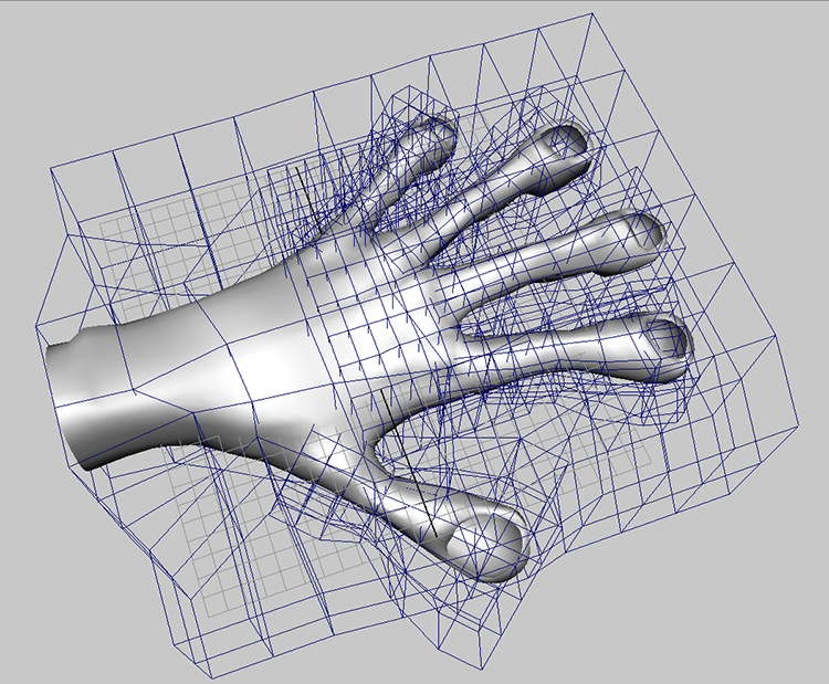
Figure 5-45: The human hand model is transformed into an alien hand by using lattices to deform the geometry.
As you can see, lattices give you powerful editing capabilities without the complication of dealing with surface points directly. Lattices can help you reshape an entire complex model quickly or adjust minor details on parts of a larger whole.
In Chapter 8, “Introduction to Animation,” you’ll animate an object using another type of deformer. You’ll also learn how to deform an object along a path.
Animating Through a Lattice
Lattices don’t only work on polygons; they can be used on any geometry in Maya and at any stage in your workflow to create or adjust models. You can also use lattices to create animated effects. For example, you can create the effect of a balloon squeezing through a pipe by animating the balloon geometry through a lattice.
In the following exercise, you’ll create a NURBS sphere with 8 sections and 16 spans and an open-ended NURBS cylinder that has no end caps:
- Choose Create ⇒ NURBS Primitives ⇒ Sphere ❏, set Number Of Sections to 8 and Number Of Spans to 16, and create the sphere.
- Choose Create ⇒ NURBS Primitives ⇒ Cylinder ❏ and check None for the Caps option. Scale and arrange the sphere balloon and cylinder pipe as shown in Figure 5-46.

Figure 5-46: Arrange the balloon and pipe.
- Select the balloon and create a lattice for it (see Figure 5-47). (This time, go into the Animation menu set and choose Anim Deform ⇒ Lattice.) Set the S, T, and U Divisions to 4, 19, and 4, respectively. You set this number of lattice divisions to create a smoother deformation when the sphere goes through the pipe.
- Select the lattice and its base in the Outliner (ffd1Lattice and ffd1Base nodes) and move the middle of the lattice so it fits over the length of the pipe (see Figure 5-48).

Figure 5-47: Create a lattice for the sphere.

Figure 5-48: Relocate the lattice to the cylinder.
- Deselect the lattice base and choose Component mode for the lattice. Select the appropriate points and shape the lattice so the middle of the lattice fits into the cylinder (see Figure 5-49).
- Select the sphere and move it back and forth through the pipe and lattice. Notice how it squeezes to fit through. If you look closely, you’ll see that the sphere starts to squeeze a little before it enters the pipe. You’ll also see parts of the sphere sticking out of the very ends of the pipe. This effect, in which geometry passes through itself or another surface, is called interpenetration. You can avoid this by using a more highly segmented sphere and lattice. If you try this exercise with a lower-segmented sphere and/or lattice, you’ll notice the interpenetrations even more. Figure 5-50 shows the balloon squeezing through the pipe.

Figure 5-49: Squeeze in the lattice points to fit the cylinder.

Figure 5-50: Squeezing the balloon through the pipe using a lattice deformer
In a similar fashion, you can create a lattice along a curve path and have an object travel through it. You’ll try this in Chapter 8.
Summary
In this chapter, you tackled NURBS modeling by going through the usual surfacing tools, from lofting to revolving. Then you explored the implications of surface History and how surfaces adjust to changes when History is enabled. You then put those lessons to work on creating a pair of glass candle holders.
This chapter also covered various modeling techniques to help you break away from typical ways of thinking. You learned how to use a lattice to adjust a polygon hand model into an alien hand, as well as how to animate a balloon pushing through a pipe. Different workflows give you the flexibility to choose your own modeling style. To make good choices, however, you’ll need to practice.
Keep at it; model everything you can get your hands and eyes on. As you’re doing that, stay on top of how you organize your nodes and keep everything named and organized.
For further practice, use this chapter as a reference to create some of the following models using NURBS surfaces and lattices to aid in shaping polygons:
- Bathroom Sink Snap a few digital stills of your bathroom sink or find some pictures on the Internet. A sink will give you a great chance to explore NURBS surfacing, making pristine curves and smooth surfaces. It may be a bit involved, but it’s not overwhelming.
- Cartoon Head Use Maya Artisan and the Sculpt Geometry tool to turn an ordinary sphere into a cartoonish head. It’s fun to use Sculpt Geometry to model. Try to make the head using only Artisan.
- Computer Mouse A PC or Mac mouse makes a great simple NURBS model.