
CHAPTER 7
Ubiquitous 3D Digital Writing Instrument
7.1 INTRODUCTION
A MAG-μIMU, which is based on Micro ElectroMechanical Systems (MEMS) gyroscopes, accelerometers, and magnetometers, is developed for real-time estimation of human hand motions. Appropriate filtering, transformation, and sensor fusion techniques are combined in the Ubiquitous Digital Writing Instrument to record handwriting on any surface. An extended Kalman filter (EKF) based on a MAG-μIMU (micro inertial measurement unit with magnetometers) is designed for real-time attitude tracking and is implemented to record handwriting.
In classic IMU applications, the Kalman filter uses the gyroscope propagation for transient updates and correction by reference field sensors, such as gravity sensors, magnetometers, or star trackers. A process model is derived to separate sensor bias and to minimize wide-band noise. The attitude calculation is based on quaternion, which when compared with Euler angles, has no singularity problem. According to this filter framework, a Complementary Attitude EKF is designed by integrating the measurement updates from accelerometers and magnetometers alternatively, in order to compensate the attitude observation error caused by sensor limitations, such as inertial accelerations, magnetic field distortion, and attitude ambiguity along each reference field. Testing with synthetic data and actual sensor data proved the filter will rapidly converge and accurately track the rigid-body attitude. The pen-tip trajectory in space can be calculated in real time based on the real-time attitude estimation. Our goal is to implement this algorithm for motion recognition of a three-dimensional (3D) ubiquitous digital pen.
Three-dimensional position tracking can be directly obtained successfully by some existing technologies. For instance, ultrasonic and infrared positioning systems with high accuracy have been developed for tracking handwriting motions, such as the Mimio [1] and e-Beam systems [2]. The basic operating principle of these systems is that, when two transceivers are fixed on white board as the position reference and broadcast ultrasonic or infrared timing signals, the two transceivers can measure the two distances to the reflector, respectively, by detecting the phase difference after receiving the echo wave from the reflector on the pen-tip,. This source positioning technology is high in accuracy and quick in response. However, the system cannot track multiple objects simultaneously, and it requires a set of receivers and a transceiver to operate, which is not convenient for users.
In our ubiquitous 3D digital writing system, the overall goal is to develop a system to track handwriting motions without the need for wave sources such as ultrasonic or infrared signals. In sourceless navigation technology, such as inertial kinematics theory, an accurate attitude is fundamental for determining and keeping track of the rigid-body position in space. Because of nonlinearity in the system dynamic equations, bias error and random walk noise from attitude sensors will be accumulated and magnified, which leads to nonlinear distortions in position tracking.
Attitude tracking is widely used in navigation, robotics, and virtual reality. Classically, the problem of distortions in position tracking is addressed by the Attitude Heading Reference System (AHRS) [3, 4]. The AHRS uses gyroscope propagation for transient updates and correction by reference field sensors. However, classically, the performance is ensured by extremely accurate sensors and hardware filters. Because of its expensive cost and large system size, the AHRS has been limited in applications, especially for mobile human position tracking applications.
With MEMS sensing technology, the inertial sensors could be built with low cost and small sizes. However, they suffer in accuracy when compared with bulkier sensors. Nevertheless, new reliable attitude tracking systems have been developed based on low-cost gyroscope sensors and on the Global Positioning System (GPS). For feedback correction, Euler angles are derived from GPS to represent spatial rotation and a Kalman filter is implemented to fuse with the attitude propagation. But GPS signals are not available for indoor applications and the GPS attitude has a resolution limit for the handwriting application [5].
For static applications such as the unmanned ground vehicle (UGV) control [6], the MEMS accelerometers work reliable as gravity sensors. Euler angles can be derived directly [7]. However, during a dynamic situation, the accelerometer measurements for the gravitational accelerations will be interfered with the inertial accelerations, which then cannot be trusted for attitude. Furthermore, the pitch attitude along the gravity axis cannot be determined.
Magnetometers experience no such crosstalk disturbance in both situations. However, following the same approach, attitude ambiguity occurs along the magnetic field direction and Euler angles cannot be derived directly. Furthermore, the Earth magnetic field is overlapped by random noise from electromagnetic interference (EMI).
A Ubiquitous Digital Writing Instrument has been developed by our group to capture and record human handwriting or drawing motions in real time based on a MEMS μIMU [8]. However, position tracking using this μIMU is not accurate because of sensor measurement noise and drifts.
Thus, an extended Kalman filter is designed to improve the system measurement accuracy of an integrated gyroscope and magnetometer device (MAG-μIMU) [9]. For the digital writing instrument application, the MAG-μIMU is affixed on a commercially available marker. During input hand motions, the filter tracks the real-time attitude of the pen with sensor bias separation and sensor random noise minimization. The attitude calculation is totally based on quaternion, which computes faster and has no singularity problem compared with Euler angles. This filter also applies to other reference field sensors for feedback, such as accelerometers or star trackers.
Based on this filter structure, a complementary extended Kalman filter for attitude is proposed to combine the accelerometers and magnetometers in the measurement update process. During the pause phase in handwriting, the complementary filter uses the accelerometers as gravity tilter for attitude reference feedback. During the writing phase, the measurement model switches to the magnetometers to avoid attitude error caused by the inertial accelerations in gravity sensor, by assuming the magnetic field distortion is tolerable within one stroke. This measurement mixture can compensate attitude ambiguity along the reference field direction for each other and rectify EMI in Earth's magnetic field.
7.2 HARDWARE DESIGN
Figure 7.1 illustrates the block diagram of a wireless MAG-μIMU with the real-time attitude filter system. The system can be divided into two parts. The first part is the hardware for the wireless sensing unit. The other part is the software for data access and 3D rotation sensing algorithms.

Figure 7.1. Wireless MAG-μMU block diagram.
The MAG-μIMU is developed for a wireless digital writing instrument and is used to record human handwriting. The MAG-μIMU is a hybrid sensing system with inertial sensors and magnetometers. The “μIMU” integrates the 3D accelerometers [10] and 3D gyroscopes [11] with strapdown installation [8]. The 3D magnetometers, “MAG” sensors, are added to measure the Earth's magnetic field [12–14]. The sensor unit is affixed on a commercially available marker to measure the inertial and magnetic information in the pen's body frame.
The output signals of the accelerometers [Ax, Ay, Az] and the gyroscopes [ωx, ωy, ωz], which are the body frame accelerations and the roll, pitch, and yaw angular rates, respectively, are measured directly with an Atmega32L A/D converter microcontroller [15, 16]. The serial Bluetooth transceiver is implemented via a USART connection with the MCU for wireless communications [17, 18]. The serial USB transceiver is integrated for transfer backup and hardware development [19]. The digital sample rate of the sensor unit is 200 Hz, and the transmit baud rate is 57.6 kbps via Bluetooth wireless connection, which ensures rapid response to human handwriting.
Figure 7.2 shows the MAG-μIMU with strapdown gyroscopes and magnetometers for attitude tracking test. The sensor system uses four-layer printed circuit board techniques for noise reduction. The dimensions are within 56 × 23 × 15 mm.
7.3 SIGNAL PROCESSING AND ANALYSIS
The stroke segment algorithm is proposed by Ref. [7] to separate the continuous pen-tip movement of character writing into independent strokes. The velocity of the pen-tip equals zero at the turning point between two consecutive strokes. This motionless phase in handwriting is important for compensating the error in attitude estimation and the position integration.

Figure 7.2. The prototype of the MAG-μIMU with a Bluetooth module.
In Ref.[7], the stroke segment is implemented based on the sample variance of inertial measurements. In probability theory, the variance of a random variable is a measure of the spread around its expected value. The sample variance is the approximation for variance with finite size N in real application. For the N sample set, the sample variance equals the unbiased mean square error, which indicates the scale of values of the sample set. Hence, the intensity of handwriting motion can be described by the sample variance of the corresponding acceleration sample set in real time.
For computational efficiency, a first-in first-out (FIFO) stack is preferred to store and process the successive sample data. The sample variance with window length N can be calculated as

where ![]() is the sample mean
is the sample mean
For a sampled time instance k, if ![]() , then k is the beginning k1 of the stroke.
, then k is the beginning k1 of the stroke.
For a sampled time instance k > k1 + W, if ![]() for k = k, k + 1, … , k + H, then k is the end k2 of this stroke.
for k = k, k + 1, … , k + H, then k is the end k2 of this stroke.
Where ![]() is a standard variance of |An| over S samples until k, σth is a threshold of the standard deviation. W is the minimum number of samples for writing a stroke, and H is the minimum number of samples to keep
is a standard variance of |An| over S samples until k, σth is a threshold of the standard deviation. W is the minimum number of samples for writing a stroke, and H is the minimum number of samples to keep ![]() from being less than σth.
from being less than σth.
As the unbiased motion intensity estimator of sample variance, the stroke segment algorithm does not have the concern of gravitational accelerations, which is changing with pen attitude. The sample variance evaluates in stochastics from the entire sample set block. This macroscopic information can efficiently discriminate hand motions by writing or trembling. However, the σth, W, and H should be predefined. These parameters have to try and test in calibration. The recognition efficiency may vary with characters of different size, especially for a different experimenter when the handwriting habit is different.
As the approximation to the expected variance, the error in sample variance caused in sampling may magnify the motion segment error when the sample set data are symmetric near the inflexion point as illustrated in Figure 7.3.
Suppose the acceleration signal for handwriting is a one-interval sine wave of 2.5 Hz as demonstrated on the blue curve in Figure 7.3. And the sample rate of the digital system is 50 Hz, which satisfies the Nyquist sampling theorem. The window length for sample variance is 4 for a quick response. The sample variance for the first sample set equals 0.0485. On the other hand, after one measurement, the sample variance for the second sample set equals 0.3394. A trivial hand tremble signal simulated on the black line has the same sample variance as the first sample set. However, the pen-tip is accelerating during the first sample set around 0.1 seconds until the stroke ended at 0.4 seconds when the velocity decelerates to zero.
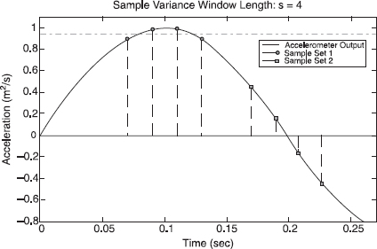
Figure 7.3. Acceleration variance underestimates motion intensity (velocity) caused by sampling error.
Thus, a Kalman filter is proposed to make use of the posterior motion information to address this problem. In a time update, the variance of acceleration is propagated as the system state as follows:
In a measurement update, the estimation is updated by the sample variance O(yk − N + 1, … , yk) as follows:
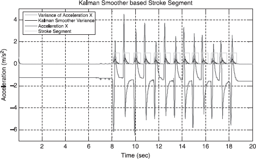
Figure 7.4. Kalman smoother-based stroke segment for motion status detection (1). See color insert.
where O(yk − N + 1, …, yk) is the sample variance for the N data set until current k.

Figure 7.4 demonstrates the experiment result to verify the segment performance. A zigzag line with 13 strokes is written to verify the response and stability of the algorithm. The window length is set to: N = 5.
The stroke segment detail is shown in Figure 7.5 below. The Kalman filter tracks the sample variance with a quick reaction corresponding to the start and end of each stroke. The variance drop at a symmetric sample set near the maximum value can be compensated by previous estimation.
7.3.1 Kalman Filtering for MEMS Sensors
The extended Kalman filter consists of two stages. In the time update stage, the quaternion increment by the gyroscopes will propagate the attitude in time. In the measurement update stage, the difference between the estimated and the measured Earth magnetic vector is implemented as feedback to correct the propagation error.
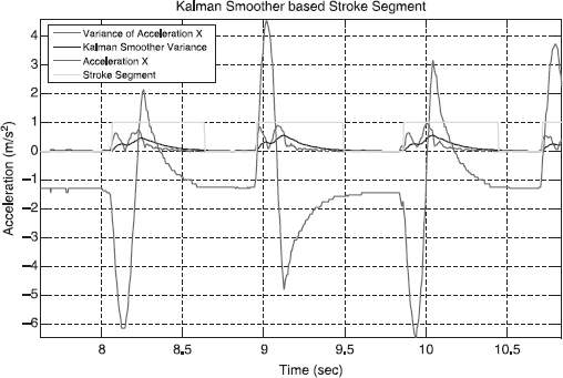
Figure 7.5. Kalman smoother-based stroke segment for motion status detection (2). See color insert.
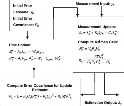
Figure 7.6. Block diagram of extended Kalman filter algorithm.
Figure 7.6 demonstrates the real-time recursive process of the extended Kalman filter algorithm.
7.3.2 Time Update Model
7.3.2.1 Attitude Strapdown Theory for a Quaternion. To propagate the attitude in time, the quaternion kinematics equation is:
where
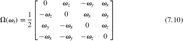
q(t) is the quaternion that denotes the current attitude for the system state. ωt are the current angular rates from the rate gyros for the system input. If Δt is small enough, the state matrix can be derived by the Euler method: Δt = t − t0 → 0,
7.3.3 Error Model for Time Update
Equation 7.13 defines the nonlinear system propagation for the state q and input ω in time update. To obtain an extended Kalman filter with a capability of gyroscope bias separation, the sensor bias model is implemented in the sate matrix by error dynamics analysis.
We define the state error of a gyro as δω:
where w(t) is a sensor's white noise and Δω(t) is the gyro bias, which is considered as constant since dt is small:
The propagation of the attitude state error, δq can be obtained by partial differentiation of Equation 7.13:
When time step dt and the previous δq is small, we assume [∂fΔt(t)/∂q(t)]δq(t) ≈ 0. By Jacobian linearization:

From Equations 7.13 and 7.17, the gyroscope bias can be separated from the system state:
Thus, the discrete time update is
In the state-space representation,
where

7.4 MEASUREMENT UPDATE MODEL
After extended Kalman filter estimation, the spatial magnetic field disturbance becomes tolerable within one stroke and the Earth's magnetic field direction remains constant within the whiteboard. It can be used as a reference for attitude in the measurement update. The three orthogonal magnetometers in the MAG-μIMU measure the geomagnetic field with respect to (WRT) the body frame. On the other hand, by coordinate transform using the propagated attitude, it can be estimated from the constant geomagnetic field WRT the Earth frame. Hence the difference between the magnetometer measurements and the transformed geomagnetic field is feedback in the measurement update of the extended Kalman filter to correct for the error in attitude propagation.
Vectors ![]() are introduced to represent the geomagnetic field WRT the Earth frame and the magnetometer outputs, respectively. The two vectors are expanded into quaternions:
are introduced to represent the geomagnetic field WRT the Earth frame and the magnetometer outputs, respectively. The two vectors are expanded into quaternions:
![]()
If quaternion n denotes the current attitude, by coordinate transform:
Multiplying the quaternion n to both sides of Equation 7.24, we obtain
![]()
where ![]() is the cross-product matrix:
is the cross-product matrix:
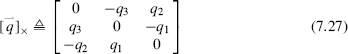
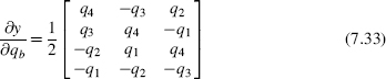
From Equation 7.26:
Thus, there is no requirement for the state q to be a unit quaternion. Let C be the measurement matrix. The measurement update of the extended Kalman filter is
According to error dynamics analysis:
where [∂y/∂qbe]δqbe = 0, [∂y/∂qb]δqb ≈ 0 when the previous attitude state error is small.
From Equation 7.30:
Thus, the discrete measurement update is
where
A mathematical derivation method is introduced to derive an extended Kalman filter to minimize random noise and input bias error. The attitude calculation is totally based on a quaternion. As proved in Equation 7.28, the attitude quaternion q does not need to be unified in iteration. Furthermore, any reference field sensor, such as star sensors and accelerometers, or a combination, can be applied to this process model.
7.5 TESTING
7.5.1 Simulation Test
Extensive simulation experiments are performed to check the convergence of the MAG Extended Kalman filter. The simulation software includes two parts: the sensor output generation and the real-time filtering. To generate the sensor output, the digital pen's physical properties and motion are modeled by the mass, inertia matrix, input forces, and torques. The kinematics and dynamics module calculates the accelerations, angular rates, and magnetic field strength under ideal conditions. The sensors' outputs are synthesized by aliasing the random Gaussian noise and constant sensor bias. For the filter part, the sensor outputs of angular rates and magnetic field strengths are processed by the extended Kalman filter in real time. The attitude-in quaternion from the filter output is transformed into Euler angles for display.

Figure 7.7. Synthetic sensor measurement. See color insert.
Figure 7.7 shows the simulated sensor output. For rotational motion analysis, the input forces are set as [0, 0, 0]. To simulate a complex orientation, the torque vector in roll, pitch, and yaw: [L, M, N] are set as
The zero mean Gaussian noises are added to the ideal sensor outputs. The absolute maximum error amplitudes are 1.3 degree per second for the gyros and 0.04 Oersteds for the magnetometers, respectfully. The initial attitude starts from 100 degrees in yaw angle. A constant sensor bias of 5 degrees per second is applied in yaw gyroscope output to verify the algorithm.
7.5.2 Experiment Test
Figure 7.8 illustrates the attitude result displayed in Euler angles. With the tracking ability of the extended Kalman filter, the initialization of the system state is simple. The attitude quaternion and gyro biases are set to zero. After iteration, the extended Kalman filter will estimate the gyro bias and remove it from the system state. According to magnetometer feedback, the filter's attitude estimation will converge and keep tracking automatically. The dashed line in Figure 7.8 shows the attitude propagated by the raw output from the gyroscopes. As shown in the figure, the random noise and bias error causes a large drift in the rolling, pitching, and yawing compared with the filter output.

Figure 7.8. Simulation attitude comparison: filter result and gyroscope propagation. See color insert.
The extended Kalman filter was tested using real sensor measurements. The MAG-μIMU transmits the digital sensor measurements to the computer wirelessly via the Bluetooth connection. The filter software in the computer processed the sensor data and calculated the attitude and sensor bias in real time.
The MAG-μIMU was held still for 4 seconds. Then continuous 90-degree rotations were performed to test the tracking performance. The sensor module was rotated counterclockwise for 90 degrees and clockwise back to 0 degrees along the sensing axis of the roll gyroscope. At the end of the seventh rotation, the MAG-μIMU was suddenly held still again to test the convergence capability from dynamic input to static input.
Figures 7.9 and Figure 7.10 show the six raw sensor output and the estimated attitude in Euler angles. Within the first iteration, the estimated attitude converged according to the observations from the magnetometers. The dashed lines show the attitude propagated by raw output from the gyroscopes. The sensor errors accumulated and caused the attitude drift.
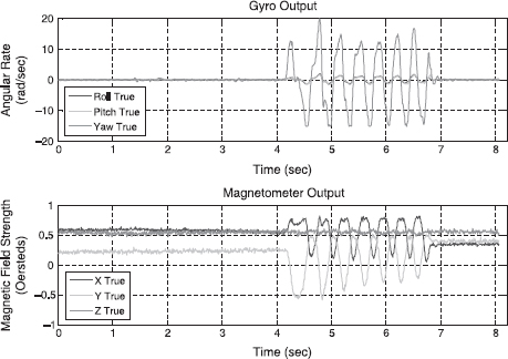
Figure 7.9. Real sensor data from MAG-μIMU. See color insert.

Figure 7.10. Experiment attitude comparison: filter result and gyroscope propagation. See color insert.
7.6 WRITING APPLICATION BASED ON ATTITUDE EKF COMPENSATION
The sensor measurements from MEMS accelerometers include gravitational accelerations as well as inertial accelerations. Because of the spring mass model of a sensor structure, these two terms cannot be separated from each other. The gravitational accelerations denote the constant gravity force projected to the sensing axes, which can be used as a reference for pen attitude. The inertial accelerations specify the translation and rotation of a rigid body when the pen is moving by handwriting. Hence, gravitational accelerations become a bias for inertial navigation, which needs to be balanced. On the other hand, during handwriting, the inertial acceleration interferes with the reference attitude calculation.
Magnetometers for attitude reference do not have such a disturbance because the magnetic field is irrelative to motion. However, the prevailing EMI will influence the measurement of the Earth's magnetic field in direction and strength. For instance, a conductor can bend the magnetic flux of the Earth's magnetic field because of magnetization. Besides, the Earth measurement may interfere with additive magnetic field error. As part of the electromagnetic field, the magnetic field exists when there is a changing electric field, and vice versa. A changing electric field can be caused by AC current, coil, capacitor, and antenna effect of conductor for electromagnetic induction. Another additive magnetic source may be directly induced by magnet, relay, monitors, transformer, and wireless communication device, such as mobile phone and Bluetooth. As a result, in real applications, the direction and strength of a measured magnetic field changes with different positions because of a complex environment.
Furthermore, the attitude from the accelerometer or magnetometer has ambiguity along the reference field direction, which is in the yaw and roll directions, respectively.
Assume the magnetic field noise is tolerable within one stroke space for the handwriting application; the tracking problem of the pen attitude is addressed by a complementary filter combining the ACC-EKF and MAG-EKF. In a time update, the attitude is propagated by angular rates based on the quaternion model. In a measurement update, during handwriting, the magnetometer model is implemented as an attitude reference with no inertial noise; and in the motionless stage between strokes, the estimation error caused by EMI can be rectified by accelerometers working as gravity tilter. The measurement update from the combination of ACC-EKF and MAG-EKF is complementary to filter the reference error and to compensate the attitude ambiguity for each other.
For complementary EKF, the measurement model of the attitude EKF, y = Cq, as introduced in Equation 7.30:

Figure 7.11. Complementary attitude EKF diagram.
where ![]() is the measurement vector for the gravitational field or magnetic field as attitude reference. The
is the measurement vector for the gravitational field or magnetic field as attitude reference. The ![]() denotes the reference field vector in the Earth's frame.
denotes the reference field vector in the Earth's frame. ![]() is applied for accelerometer tilters and
is applied for accelerometer tilters and ![]() is for magnetometers.
is for magnetometers.
However, for continuous handwriting, the magnetic field varies in direction and strength corresponding to different places such that ![]() . For the complementary attitude EKF, before switching from accelerometer attitude feedback, the magnetometer measurement should be synchronized for the magnetic reference difference. From Equations 7.40 and 7.41, the measurement update model should be calibrated and initialized as
. For the complementary attitude EKF, before switching from accelerometer attitude feedback, the magnetometer measurement should be synchronized for the magnetic reference difference. From Equations 7.40 and 7.41, the measurement update model should be calibrated and initialized as
where

The ![]() is latest the attitude filter tracking result, and the
is latest the attitude filter tracking result, and the ![]() is the first magneto meter observation after the switch. The writing and pause of hand motion status for the Sync Switch can be implemented by the Stroke Segment Kalman Filter, which will be introduced later. Figure 7.11 demonstrates the diagram of the complementary attitude EKF for the real-time handwriting application.
is the first magneto meter observation after the switch. The writing and pause of hand motion status for the Sync Switch can be implemented by the Stroke Segment Kalman Filter, which will be introduced later. Figure 7.11 demonstrates the diagram of the complementary attitude EKF for the real-time handwriting application.
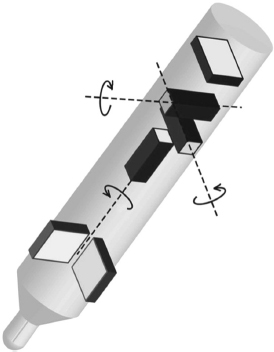
Figure 7.12. The MAG-μIMU system structure for a wireless digital writing instrument.
Figure 7.12 illustrates the MAG-μIMU sensor structure of the digital writing system for position tracking.
According to the strapdown kinematics theory [20] the body frame accelerations are transformed to the Earth's frame by a direct cosine matrix (DCM). After compensating for the gravitational and rotational accelerations, the translation accelerations integrate into 3D trajectories in space. Thus, any 2D human handwriting is recorded in real time if the pen touches the white board plane.
where ![]() are the body frame accelerations: [AX, AY, AZ]. q is the quaternion representing the pen attitude.
are the body frame accelerations: [AX, AY, AZ]. q is the quaternion representing the pen attitude. ![]() is the gravity vector: [0, 0, −g].
is the gravity vector: [0, 0, −g].
According to the kinematics equations, the accelerometers are designed to mount close to the pen-tip for more sensitivity for handwriting motion and depression for the rotational accelerations. The magnetometers are fixed on the pen bottom to reduce the magnetic field distortion effect by the metal white board.

Figure 7.13. Experiment setup for Digital Writing Instrument with MAG-μIMU.
7.7 EXPERIMENTAL RESULTS OF AN INTEGRATED SYSTEM
The handwriting experiments are performed to verify the algorithm integration for the Digital Writing Instrument system and to test the performance of attitude and position tracking for handwriting recording.
Figure 7.13 illustrates the writing experiment setup with the wireless Digital Writing Instrument based on MAG-μIMU.
In this experiment, an 8-cm × 10-cm capital letter “A” with four strokes is written on a horizontal plastic table in normal writing speed. During handwriting, the MAG-μIMU measured the nine-channel motion information of X, Y, Z acceleration, roll, pitch, yaw angular rate, and X, Y, Z magnetic field strength with a 200-Hz sampling rate. After wireless transmission via Bluetooth, the complementary attitude EKF in a computer estimated the pen attitude in real time with a dynamic switch to combine the accelerometer and the magnetometer update, which is the controlled by stroke segment Kalman filter. After coordinate transform by attitude tracking result, and zero velocity compensation (ZVC), the handwriting trajectory in the Earth's frame was obtained stroke by stroke. Figure 7.14 shows the nine-channel sensor output WRT the body frame from the MAG-μIMU.
The motion information for 3D accelerations, angular rates, and magnetic field strength WRT the body frame are transformed after calibration experiments as shown in Figure 7.15 Random noise prevails in sensor observations.
Meanwhile, the body frame acceleration in the x-axis is used to detect the writing or pause of hand motion by stroke segment Kalman filter in real time (Figure 7.16). This writing status information can control the switching in the measurement update.

Figure 7.14. Digital Writing Instrument sensor outputs. See color insert.

Figure 7.15. Nine-channel motion information WRT the sensor frame. See color insert.

Figure 7.16. Stroke Segment Kalman Filter as sync switch for measurement update. See color insert.

Figure 7.17. Tracking result of complementary attitude EKF. See color insert.

Figure 7.18. Accelerations WRT the Earth's frame by complementary attitude EKF. See color insert.
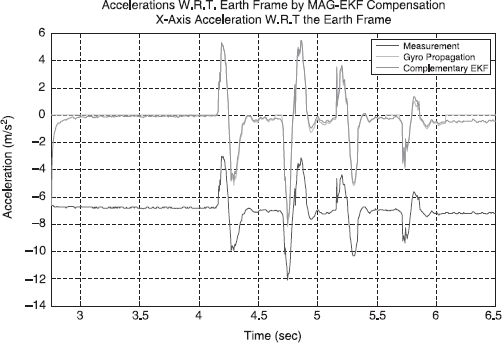
Figure 7.19. Performance comparison for the acceleration coordinate transform in x-axis. See color insert.
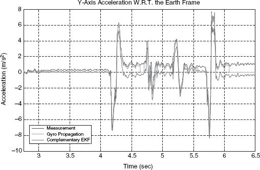
Figure 7.20. Performance comparison for the acceleration coordinate transform in y-axis. See color insert.
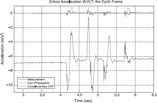
Figure 7.21. Performance comparison for the acceleration coordinate transform in z-axis. See color insert.
The pen attitude in quaternion is estimated by the complementary attitude EKF in real time. For comparison, the attitude is also displayed in Euler angles as shown in Figure 7.16. After 0.26 sec, the filter is tracked to true attitude for 44.3 degrees in roll.
As shown in Figure 7.17, the acceleration WRT the Earth's frame is obtained by coordinate transform according to the filter result for pen attitude in real time.
Figure 7.18, 7.19-1.21 demonstrate the performance for the transformation of the acceleration's coordinate from the sensor frame to the writing frame by the complementary attitude EKF quaternion output. For comparison, the transformed acceleration by noisy gyroscope propagation and the sensor measurement are shown on the green and blue lines, respectively.
During handwriting, the pen attitude is changing with hand motion. The attitude error caused by noisy measurement will lead to nonlinear bias by coordinate transform for the Earth's frame accelerations.
As the pen tip is moving on the write board which is the x–y plane of the Earth's coordinate system, the Earth's frame acceleration on the z-axis should equal zero.
The real-time writing result for “A” is shown in Figure 7.22, which started from the origin (0,0). Because of noise and bias in the accelerometer measurements, the position error was accumulated and magnified by double integration and caused it nonlinear drift and distortion in the writing trajectory.
Thus, the zero velocity compensation is implemented to improve position accuracy. The stroke segment is improved using the z-axis acceleration in Earth's frame by coordinate transform and the complementary EKF tracking result (Figure 7.23).
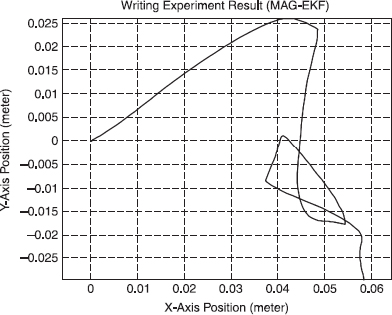
Figure 7.22. Capital letter “A” written by complementary attitude EKF.
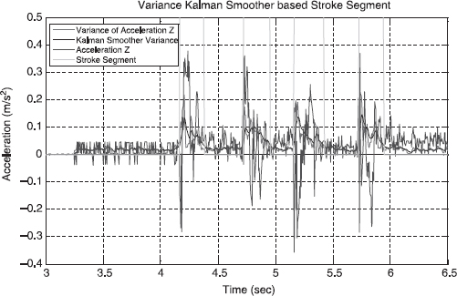
Figure 7.23. Stroke segment according to the Earth frame acceleration. See color insert.
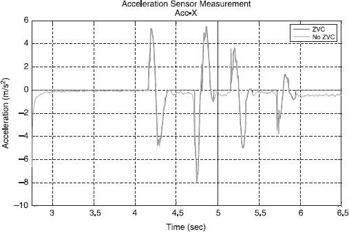
Figure 7.24. X-axis acceleration updated by zero velocity compensation. See color insert.
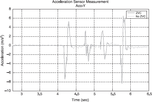
Figure 7.25. Y-axis acceleration updated by zero velocity compensation. See color insert.
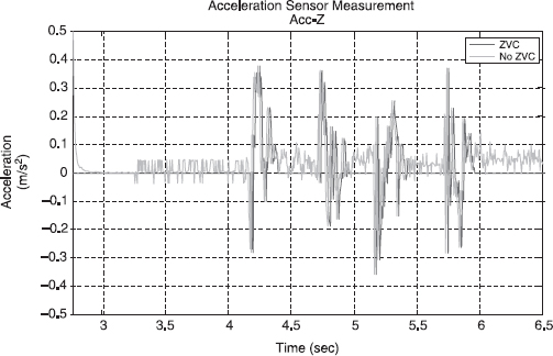
Figure 7.26. Z-axis acceleration updated by zero velocity compensation. See color insert.
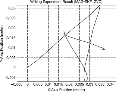
Figure 7.27. Writing result for “A” by complementary attitude EKF and ZVC.

Figure 7.28. Handwriting result for “A” using DWI system during the position tracking experiment.
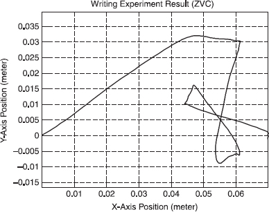
Figure 7.29. Writing result for “A” by gyro attitude propagation and ZVC.
Figures 7.24–7.26 illustrate the acceleration updated by ZVC. During the pause stage of writing, the velocity was set to zero and the position remained constant to avoid position drift.
Velocity can be corrected by ZVC. The error accumulated in velocity calculation from accelerometer noise and bias, and magnetic field distortion was rectified backward after each stroke. When the sampling rate is high enough and magnetic field distortion within one stroke is tolerable, the higher order term can be omitted and the velocity error can be approximated in the linear model. However, ZVC is an offline algorithm. The letter should be written stroke by stroke to use velocity bias.
After coordinate transform using a complementary EKF attitude and ZVC, the handwriting trajectory for “A” is improved as shown in Figure 7.27.
Figure 7.28 demonstrates the handwriting result during this experiment for comparison. The capitialized “A” is written by the marker in the Digital Writing Instrument on A4 size paper.
Compared with Figure 7.25, there is drift error and distortion in Figure 7.29, which is obtained by coordinate transform using gyro attitude propagation and ZVC.
7.8 CONCLUSION
A wireless Digital Writing Instrument based on MAG-μIMU has been developed with 3D accelerometers, gyroscopes, and magnetometers with strapdown installment. Through a Bluetooth connection, the motion data are transmitted to a computer with a 200-Hz sampling rate for real-time process in attitude determination and position tracking.
REFERENCES
1. Virtual Ink Corporation. Mimio Studio user's guidance, 2005. http://www.mimio.com/products/documentation/mimiostudio_usersguide.pdf.
2. Lucia, Inc. eBeam Interactive Whiteboard Technology, 2006. http://www.e-beam.com/downloads/files/WhatIseBeam.pdf.
3. Sagem Avionics, Inc. APIRS F200-AHRS Brochure, 2006. http://www.sagemavionics.com/Products/Brochures/APIRS-F200.pdf.
4. Watson Industries, Inc. AHRS-E304 Manual, 2006. http://www.watson-gyro.com/files/attitude_reference_AHRS-E304_spec.pdf.
5. R. C. Hayward, D. Gebre-Egziabher, M. Schwall, J. D. Powell, and J. Wilson, “Inertially-aided GPS-based attitude heading reference system (AHRS) for general aviation,” in Proc. of ION GPS, Kansas City, MO, Sept. 1997.
6. A. K. Brown, “Test results of a GPS/Inertial navigation system using a low cost MEMS IMU,” in Proc. 11th Annual Saint Petersburg International Conference on Integrated Navigation System, Saint Petersburg, Russia, May 2004.
7. E.-S. Choi, W. Chang, W. C. Bang, J. Yang, S. J. Cho, J. K. Cho, J. K. Oh, and D. Y. Kim, “Development of the gyro-free handwriting input device based on inertial navigation system (INS) theory,” in Proc. of The Society of Instrument and Control Engineers Annual Conference, Vol. 2, 2004, pp. 1176–1181.
8. G. Zhang, G. Y. Shi, Y. L. Luo, H. Wong, Wen J. Li, Philip H. W. Leong, and M. Wong, “Towards an ubiquitous wireless digital writing instrument using MEMS motion sensing technology,” in 1EEE/ASME Proc. Advanced Intelligent Mechatronics, 2005, pp. 795–800.
9. Y. Luo, C. C. Tsang, G. Zhang, Z. Dong, W. J. Li, and P. H. W. Leong, “An attitude compensation technique for a MEMS motion sensor based digital writing instrument,” in Proc. of IEEE Int. Conf. on Nano/Micro Engineered and Molecular Systems, 2006.
10. Analog Devices, Inc. Low-Cost Ultracompact ± 2g Dual-Axis Accelerometer ADXL311 Data Sheet (Rev. B, 01/2005), 2005. http://www.analog.com/UploadedFiles/Data_Sheets/243920868ADXL311_B.pdf.
11. Murata Manufacturing Co., Ltd. GYROSTAR Piezoelectric Vibrating Gyroscopes Data Sheet (No. S42E, 06/2006), 2006. http://www.murata.com/catalog/s42e.pdf.
12. Koninklijke Philips Electronics N. V. Magnetic Field Sensor KMZ51 Data Sheet (06/ 2000), 2006. http://www.nxp.com/acrobat_download/datasheets/KMZ51_3.pdf.
13. Koninklijke Philips Electronics N. V. Magnetic Field Sensor KMZ52 Data Sheet (06/ 2000), 2006. http://www.nxp.com/acrobat_download/datasheets/KMZ52_1.pdf.
14. Honeywell International, Set/Reset Function for Magnetic Sensors (08/02), 2003. http://www.ssec.honeywell.com/magnetic/datasheets/an213.pdf.
15. Atmel Corporation. 8-bit AVR Microcontroller with 32 Bytes In-System Programmable Flash ATmega32(L) Data Sheet (Rev. I, 04/06), 2006. http://www.atmel.com/dyn/resources/prod_documents/doc2503.pdf.
16. R. H. Barnett, S. Cox, and L. O'Cull, Embedded C Programming and the Atmel AVR, Delmar, Clifton Park, NY, 2003.
17. BlueRadios, Inc. Class 1, Class 2 and 3 BR-C30 ver 1.2 Module Specification, 2006. http://www.blueradios.com/BR-C30.pdf.
18. IVT Corporation, BlueSoleil 2.3 Commercial Version Release Note (Ver. 2.3, 07/06), 2006. http://www.bluesoleil.com/Download/files/IVT_BlueSoleil_%28Standard%29_Release_Note.pdf.
19. Future Technology Devices International Ltd. FT232BM USB UART (USB-Serial) I.C. Data Sheet (Ver. 1.8, 2005), 2006. http://www.ftdichip.com/Documents/DataSheets/ds232b18.pdf.
20. D. H. Titterton and J. L. Weston, Strapdown Inertial Navigation Technology, 2nd Edition, AIAA, Reston, VA, 2005.
FURTHER READING
W.-C. Bang, W. Chang, K.-H. Kang, E.-S. Choi, A. Potanin, and D.-Y. Kim, “Self-contained spatial input device for wearable computers,” in Proc. 7th IEEE Int. Symp. on Wearable Computers, pp. 26–34, Oct. 2005.
D. Gebre-Egziabher and D. Powell “A DME-based area navigation systems for GPS/WAAS interference mitigation in general aviation applications,” in Proc. IEEE Position Location and Navigation Symposium, pp. 74–81, Mar., 2000.
L. Monteiro, T. Moore, and C. Hill, “What is the accuracy of DGPS?” The Journal of Navigation, Vol. 58, pp. 207–225, 2005.
Wikipedia foundation Inc. Global Positioning System, 2006. http://en.wikipedia.org/wiki/Global_Positioning_System.
Intelligent Wearable Interfaces, by Yangsheng Xu, Wen J. Li, and Ka Keung C. Lee
Copyright © 2008 John Wiley & Sons, Inc.