
CHAPTER 6
Fingertip Human–Computer Interface
6.1 INTRODUCTION
A computer is one of the most common devices in our lives now. Because of the development of mobile computing, pocket PCs or wearable computers allow computers and computer-related devices to merge human lives.
In this chapter, we discuss the advent in Micro ElectroMechanical System (MEMS) sensing and wireless technologies to develop a novel computer input system named the micro input devices system (MIDS, in short). It enables multifunctional input tasks and allows the overall shrinkage in size of the graphical user interface (GUI) interface devices (see Figure 6.1). The working principle lies on using the motion sensing technique to capture human motion and to convert the motion information to appropriate computer input commands. In terms of mobile computing, we envision MIDS to serve the functions of the current-day mouse, keyboard, and light-pen such that it will allow users to input text, draw graphical image, move curser, and perform drag-and-drop motion.
With the motion sensing ability of the MIDS, it can be further explored to measure the motion of robotic grasping manipulators and to control the grasping robot hands; hence, MIDS could replace the robotic gloves, which are currently used to interface with robot hands. The details will be shown in this chapter.
Conventional input devices, such as mouse and keyboard, and more advanced input devices, such as three-degree-of-freedom and six-degree-of-freedom controllers have relied on movement detectors, potentiometers, optical position detectors, liquid level tilt sensors, magnetic sensors, and button switches as inputs. Position is determined by reading the value of a movement detector and/or potentiometer attached to the input device. A potentiometer is simple and very inexpensive, and it is designed to work with standard computer interfaces. The potentiometer uses the desktop as a position reference. The biggest limitation of potentiometers is not performance, but the fact that they limit the motion and location of the user to a desktop location.
In addition, a traditional input device is a poor match to mobile devices [e.g., personal digital assistant (PDA)] and three-dimensional (3D) applications such as the playing of 3D, shooting, and racing games. A mobile computing user can use the simple stylus to control the PDA. A game player desiring a better experience can buy a separate steering wheel. What if it were possible to make a single controller that could simulate all of these?
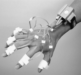
Figure 6.1. Wearable wireless MIDS prototype (this version includes five rings and one wrist watch).
Accelerometers are sensors that can measure acceleration. MEMS accelerometers can measure static gravity fields, allowing inclination measurement. Using gravity as a positional reference eliminates the need for working on the table and a connection to the desktop, i.e., available in “mid-air.” Available tilt sensors are primarily of the electrolytic fluid variety. A glass or plastic vial is filled with a conductive fluid; electrodes in the fluid are used to sense a resistance, and as the device is tilted, the resistance changes. One problem with these sensors (which use gravity as an input) is their sensitivity to shock, vibration, and lateral acceleration. These signals, common to game playing, cause the liquid to slosh around in the vial producing a nonusable signal from the tilt sensor. These sensors typically have a response as poor as 0.5 to 1 Hz, about 50 times less than that required for a high-quality input device. Accelerometers used as inclinometers provide a better solution. New devices available today are just as accurate as conventional tilt sensors, but they have a response of better than 50 Hz and do not suffer the slosh phenomenon. They are also considerably smaller and lighter than liquid tilt sensors, allowing a reduction in the size and weight.
A generalized methodology for designing MIDS for different applications is covered in this chapter. MIDS combines MEMS accelerometers, wireless technology, and advanced algorithms to serve as a virtual mouse and keyboard that will allow users to input text, move cursor, perform drag-and-drop motion, and draw computer graphics (CG) on the desk or in mid-air. Therefore, this novel computer–human interface system allows the user to use only one input system to handle both graphical-based and text-based input interfaces. This work is also applied to the PDA for a motion-based controller successfully.
6.2 HARDWARE DESIGN
MIDS technology (MIDS-tech) is a method that makes use of motion data to generate operation commands for additional analysis. MIDS-tech includes the system design, software development, and motion-to-command algorithms so that it is a complete solution for handling motion analysis as well as for generating control-input commands.
A MIDS (a system made of one or more sensors and other peripheral subsystems such as Bluethooth wireless transmitters, power-storage units, etc.) can measure acceleration, velocity, and position of the fingertips, and thus, it can allow users to switch between different virtual input devices based on simple and customized finger motions to switch modes. In addition, a motion sensing device could also be developed based on MIDS-tech to analyze human motion in sports science, or as a monitoring system to keep in check equipment in an assembly line. MIDS could also be applied to robot-related applications such as in controlling the grasping motion of real/virtual robotic hands. Moreover, it could function also as a computer game controller to let players play a video game using their body motion.
MEMS sensors play a major role in MIDS in developing a functional system because of their low cost and miniaturized size. We used MEMS sensors to measure multidimensional motions of human body parts such as those at each finger and hand, followed by the wireless transmission of these motion data to the computer for input information process.
The MIDS has two versions: wired and wireless. Both of them consist of four main system units: 1) sensing unit including multiaxes MEMS sensors, 2) signal processing unit including microcontroller unit (MCU), 3) interface unit including the interface board connected to a PC or a laptop, and 4) driver interface program. For the wireless system, a wireless transmitter and receiver are connected to the MCU and to the interface board, respectively. The schematic diagram of MIDS is shown in Figure 6.2.

Figure 6.2. The MIDS schematic diagram including four main system units: 1) sensing unit, 2) signal processing unit, 3) interface unit, and 4) driver interface program.
The multiaxes MEMS sensors can be placed in MIDS rings or in any other form, which are worn on the fingers and are electrically connected with an MCU through wired or wireless transmission that acts as a communication link between the MCU and the PC. The MCU is used to analyze the sensor signals and to encode the signal for signal transmission. In the interface board, the analyzed signals are transmitted to the PC. It can use either a serial port or a USB port of the PC. Using the serial driver IC, MAX232 manufactured by Maxim Integrated Products Inc., Sunnyvale, CA [1], the received data are converted to RS232 format (computer-readable serial format) and then passed to the serial port of the PC. Using the USB driver IC (such as FT8U232BM manufactured by Future Technology Devices International Limited, Glasgow, United Kingdom [2]) and the USB port, the transmission rate can be increased and the PC can also supply the power through the USB port. The driver interface program is used to record the motion data and to convert the motion information to computer input command. It is a user-friendly interface, and it allows the users to change the parameters (e.g., the speed and sensitivity of the mouse cursor movement) for computer control.
6.2.1 MEMS Accelerator for Motion Detection
As mentioned, MEMS sensors play a major role in MIDS because they are low cost and have a miniaturized size. There are many types of MEMS sensors in the market such as accelerometer and gyroscope. Different sensors have different characteristics. MEMS sensors have been commonly used in the past. For example, Analog Devices, Norwood, MA [3], Memsic Inc., North Andover, MA [4], and STMicroelectronics, Geneva, Switzerland [5] designed and manufactured their own MEMS sensors.
6.2.1.1 Accelerometer. Accelerometer is used to measure the acceleration of a moving object. It is commonly used in automotive, automation machines, measuring instruments, and monitoring systems. For example, acceleration signals can be integrated with velocity and can be doubly integrated to form displacement. Accelerometer can detect the motion, vibration, and shock of machines and automobiles, and they can measure gravity such that it can be used to determine the orientation of the object such as tilt and inclination.
In this work, MEMS accelerometers manufactured by Analog Devices Inc. are used. These sensors are produced by surface micromachining. Surface micromachining is a technique for building MEMS structures in silicon. Combined with onboard signal conditioning circuits, complete micro electromechanical systems can be built on a small piece of silicon such that the size of sensors can be in micro-scale. Therefore, surface micromachining allows the consistent and repeatable production of large quantities of devices at low cost. It is the reason for choosing these MEMS sensors.
There are three types of MEMS accelerometer: single axis, dual-axis, and three-axis (see Figure 6.3). These accelerometers can be used to measure the acceleration in Cartesian space (xyz directions).
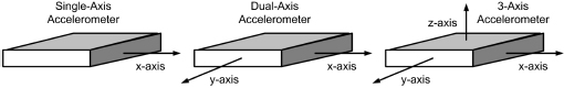
Figure 6.3. Three types of accelerometer: single axis, dual-axis, and three-axis.
The MEMS sensors are capable of measuring acceleration with a full-scale range from below ±1.0 g to above ±100 g (Note that 1.0 g = 9.81 ms−2). The sensors can measure both dynamic acceleration, such as vibration and shock, and static acceleration such as gravity. The sensors employ the principle of relating the capacitance variation between the polysilicon comb-drives to acceleration (as illustrated in Figure 6.4).
When movement is applied to a sensor, the proof mass is moved such that the capacitances between the two fixed outer plates (C1 and C2) are changed. The acceleration can then be determined by the ratio of the capacitances. With different onboard signal conditioning circuits, the sensors can provide analog or digital output voltages. The analog output voltages are available in absolute voltage (which is independent of supply voltage) and ratiometric voltage (which is proportional to supply voltage). The digital output voltages are signals with a duty cycle (which is the ratio of pulse width to period and it is in the form of a pulse-width module, PWM) [6].
As an example, a capacitive accelerometer can be made by using silicon MEMS etching techniques. A model is shown in Figure 6.5, where m is the proof mass, c is the damping coefficient, k is spring constant, δo is the gap distance, ξ is the input motion and xo is the output motion. The input motion will change the gap distance δ (with the initial gap distance δo), thereby changing the capacitance between two electrodes. Hence, the acceleration can be measured by monitoring the capacitance.
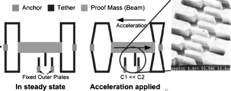
Figure 6.4. Illustration of sensor operation.
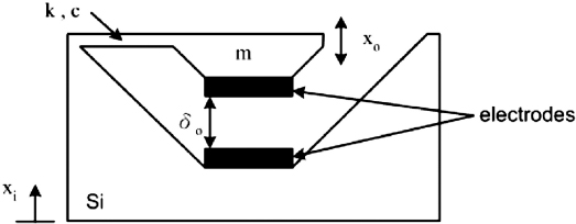
Figure 6.5. Model of a MEMS capacitive accelerometer.
The capacitance between the electrodes is
Even though capacitive sensing technique is matured now, it still has some problems when the mechanical sensors are miniaturized: 1) matching air-gap and CMOS capacitors, 2) thermal drift, 3) variation in driving voltage, and 4) variation of δo of air gap. Except for the thermal drift problem, we can gain an insight into these problems by doing the following analyses.
Assume that a simple capacitive circuit has a capacitor that will change its capacitance due to a mechanical input, the circuit analysis diagram for capacitive accelerometer modeling is shown in Figure 6.6.
Then, from the circuit analysis:
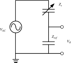
Figure 6.6. Circuit analysis for capacitive accelerometer modeling.
Let,
where δ is the gap distance between the Z electrodes in the sensing capacitor of any given time.
For the initial capacitance,
Thus,

Then, from the circuit analysis,
Let the capacitances between the electrodes be
Then,
Thus,
Hence, the output voltage of a MEMS sensor can be directly related to the displacement of a proofmass as shown in the above equation.
The ADXL202E is a MEMS-based dual-axis accelerator manufactured by Analog Devices Inc. For each axis, an output circuit converts the analog signal to a duty cycle modulated (DCM) digital signal that can be decoded with a counter/timer port on a microprocessor. The ADXL202E is capable of measuring both positive and negative accelerations (the range is ±2 g where g means 9.8 ms−2). The accelerometer can also measure static acceleration forces such as gravity, which allows it to be used as a tilt sensor.
The ADXL202E's digital output is a duty cycle modulator. Acceleration is proportional to the ratio T1/T2. The nominal output of the ADXL202E is [3]:
- 0g = 50% duty cycle
- Scale factor is 12.5% duty cycle change per g
These nominal values are affected by the initial tolerance of the device including 0 g offset error and sensitivity error. It is necessary to perform a calibration. The period of duty cycle, T2, does not have to be measured for every measurement cycle. It need only be updated to account for changes due to temperature (a relatively slow process). Since the T2 time period is shared by both X and Y channels, it is necessary only to measure it on one channel of the ADXL202E. The acceleration value A (in terms of g) is
With the acceleration information in x- and y-directions, the pitch and roll angle can be determined as follows:
ADXL202E can be used to measure a full 360° of orientation through gravity (see Figure 6.7). When one axis output is reading a maximum change in output per degree, the other is at its minimum (90° perpendicular to each other).
To find the tilt angle α in 360° scale, it can be defined as four phases. It can be obtained by the value of the acceleration in y- and x-directions according to the phases. The detailed formulas are shown in Table 6.1.
6.2.2 Signal Processing and Analysis
Many MCUs can handle a fast-speed DCM signal. The Atmega8515 manufactured by Atmel Corporation [7] is selected in our work. In the signal processing unit of MIDS, a programmable MCU is used to count the duty cycle of the ADXL202E such that the acceleration values can be determined. The illustration of the data acquisition of the MCU for DCM signal from ADXL202E is shown in Figure 6.8.

Figure 6.7. Using x- and y-direction output to measure 360° of tilt.
Table 6.1. Detailed Formulas for Calculating the Tilt Angle α in 360° plane


Figure 6.8. Illustration of the data acquisition of the MCU.
In Figure 6.8, Xout and Yout are DCM signals for x-direction and y-direction from ADXL202E. The points Txa, Txc, Txe, and Txg are the raising edge of Xout, whereas the points Txb, Txd, and Txf are the falling edge of Xout. Similarly, the points Tya, Tyc, Tye, and Tyg are the raising edge of Yout whereas the points Tyb, Tyd, and Tyf are the falling edge of Yout. Since the T2 for Xout and Yout are the same, the period of duty cycle can be calculated from either Xout or Yout to get the value of T2.
At the beginning of the program, the first raising edge will be recorded. Assume Xout is faster than the Yout (see Figure 6.8); Txa will be recorded in order to determine the start of the T2. When the second raising edge of Xout appeared, T2 can be determined by (Txc − Txa) and Txc will then be recorded in order to determine the start of Tx1.
At this stage, the MCU will monitor both Xout and Yout to record the raising or falling edges. Thus, Tyc from Yout will then be recorded in order to determine the start of Ty1. When a falling edge appeared in Yout, Tyd will then be recorded to determine Ty1. After that, a falling edge appeared in Xout so the Txd will be recorded to determine Tx1. Now, T2, Tx1, and Ty1 have been determined. For the ADXL202E, the acceleration value Aout for x- and y-directions can be calculated and represented by 8-bit signals.
On the other hand, the button press action is also checked. Through the Universal Synchronous and Asynchronous serial Receiver and Transmitter (USART) from the MCU, the Aout signals for x- and y-directions as well as the button status (b1, b2, etc.) will then be transmitted in serial format within the time T2 − T1 (i.e., Tout <T2 − T1). Then the Tx1 or Ty1 of the next duty cycle will then be determined continuously.
Note that Tout must be less than T2−Tx1; otherwise, there will be a data lost problem. The details to prevent this problem will be discussed in the coming section on the different applications. T2 will be updated every second (the threshold is 150, i.e., 150 samples per second) so that the error due to temperature change will be minimized. The program flow of the signal processing unit is shown in Figure 6.9.
6.2.2.1 Noise Filtering and Signal Processing. For some applications such as human–machine interface and computer input device, the high-frequency noise signal (which sometimes is from the human hand shaking) should be eliminated. A low-passed filter is adopted to eliminate such high-frequency noise. When the driver interface receives the sensor data and obtains the acceleration value, the acceleration signals are first passed through a first-order Butterworth filter before converting into the control commands. The transfer function of the first-order low-pass Butterworth filter is

Figure 6.9. Program flow of signal processing unit.
Note that fc is the cutoff frequency (Hz) and fs is the sampling frequency (Hz).
With bilinear transformation, the digitalized expression of the output in time domain is
Note that the cutoff frequency is selected to be = 25 Hz for human motion application, which is double that of the maximum frequency of human hand motion (∼10 Hz). For other applications such as machine monitoring, the cutoff frequency should be based on the specific requirement.
6.2.3 Radio-Frequency (RF) Wireless System
Many RF wireless solutions are available in the market. A pair of LC series transmitter and receiver modules manufactured by LINX technology [8] is selected. The LC series wireless module is capable of transferring serial data at distances in excess of 300 feet. No external RF components, except an antenna, are required. Moreover, it is low cost, has ultra-low-power consumption, is a compact surface-mount package, has fast enough data rates to 5000 bps, and has a direct serial interface that supports serial data transmission.
6.2.4 System Evaluation
Experiments were performed to demonstrate motion detection in 3D space using a simple version of MIDS. This simple version of MIDS includes two 3D motion sensing rings and one MIDS watch with signal processing unit and wireless transmitter. An illustration of the components of the MIDS ring is shown in Figure 6.10. Two dual-axis MEMS sensors are mounted as shown. Sensor A is placed at the top of the ring horizontally to measure fingertip accelerations in the x- and y-directions. Sensor B is placed at the side vertically to detect accelerations in the y- and z-directions. Therefore, sensor A can detect the plane motion of the fingertip and sensor B can detect the fingertip angle (relative to rotation about the mid-joint of a finger) and the vertical movement. The prototype of this simple MIDS ring is shown in Figure 6.11. On the other hand, the receiver was connected to the PC and the data were collected for analysis.
Two experiments were performed: 1) measurement of the fingertip motion in z-axis for click motion detection, and 2) measurement of the fingertip movement on x–y plane to determine the trajectories of the movement as sensed by the motion sensors. The experimental setup is shown in Figure 6.12. The data acquisition schematic is shown in Figure 6.13.
6.2.4.1 Experimental Results of Click Motion Test. Measurement for click motions in z-direction is shown in Figure 6.14, which basically shows the up and down motions of the fingertip. Three cases are distinctive in the data plot: (a) one peak, (b) two peaks, and (c) three peaks. As indicated in the figure, the time duration for each sampled motion is about 1 second. Regions (a), (b), and (c) shown in the figure correspond to single-click, double-click, and triple-click, respectively. These results show that the accelerometer could detect the click motions (even for triple-click) within a short time (about 1 second). The sampling frequency used for this experiment is about 31 Hz. The response time of the sensors are fast enough to measure the fingertip motions based on these experimental observations.

Figure 6.10. Schematic of MIDS ring.

Figure 6.11. Prototype of simple MIDS rings.
6.2.4.2 Experimental Results of Circular Motion Test. The motion of a fingertip as it traverses around a circular path was also measured. (The circular path was imagined by the experimental subject; no reference circular path was placed on a table for the subject to follow.) The time-sequence data of the two sensors on the fingertip is shown in Figure 6.15, and the corresponding displace plot in the x–y plane is shown in Figure 6.16, which indicates that the MIDS could potentially be used to perform the functions of moving a cursor on the computer screen.
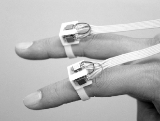
Figure 6.12. Experimental setup for motion tests.
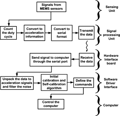
Figure 6.13. Data acquisition schematic of the simple MIDS.

Figure 6.14. MIDS click motion test in mid-air.
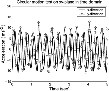
Figure 6.15. MIDS circular motion test on a desk (time sequence acceleration).
With the above results, we have shown that the MIDS could potentially handle the operations of existing common input devices. For the mouse, MIDS could detect the movement on x–y plane such that it could move a cursor and handle the click motion; for the keyboard, MIDS could detect the finger movement (as a finger moves from one key to another) and the key-press action (as the finger types a key); for the light pen, MIDS could capture the trajectory of the finger such that it can draw a desired curve in either a fixed two-dimensional (2D) plane or in 3D space.

Figure 6.16. MIDS circular motion test on a desk.
6.3 SPECIFIC APPLICATIONS
Motion is a general term describing the act or process of changing position and place of a dynamic object. Motion is really a very important part in our life. For sports, many athletes use equipment to evaluate their motion during exercises. For industry, many engineers use motion sensing systems to monitor machines in the assembly lines.
As mentioned, MIDS can measure many types of motion. Using MIDS technology, different motions sensing systems can be developed. In this section, motion sensing devices (MSDs) developed for human–robot interaction, computer-mouse on a fingertip, computer game control, and PDA interation are presented.
6.3.1 Human–Robotic–Hand Interaction Using MIDS
Nowadays, fingered robots are becoming more ubiquitous, e.g., in the manufacturing industry, robot hands are now used to handle many duplicated tasks such as grasping in product assembly line. Human-like robots such as Honda's humanoid robot: ASIMO [9] and Sony's SDR-4X [10] are commercially available in the market. These robots can be classified into two different types: those controlled by the CPU automatically and those manipulated by operators. For automated robot hands, MSDs are essential for measuring the motion of the robot hands for quality control and system evaluation. For manual controlled robot hands, a user-friendly input device can be useful to the operator in controlling manipulators such as grasping robotic hands. In this case, a multifunctional device is needed to handle both the motion sensing function and the control-input function. In this section, we will show that MIDS will enable many new capabilities in terms of robotic sensing and control, including a multifunctional device for sensing and controlling robotic hands.
In the robotics area, studies in grasping using robotic hands have been extensive in the past decade [11–13]. Some researchers have focused on theoretical analyses. For example, Ding et al. proposed an algorithm for computing a form-closure grasp on a 3D polyhedral object [11]. The computational cost of this algorithm is less dependent on the complexity of the object surface such that it can help the robotic hand to grasp objects with many contact points. Also, Hasegawa et al. proposed a method to generate the grasping point and the regrasping phase [12]. Moreover, Cheah et al. proposed a method to solve a task-space feedback control problem of multifingered robotic hands with uncertain Jacobian matrices [13].
In this section, we try to further explore MIDS to ultimately replace the robotic gloves that are used today to interface with virtual and real robotic hands. MIDS not only can be used to develop or evaluate control algorithms by measuring the motion of robotic hands, but it may also act as a human–robot interface that allows users to control the robotic hands by their own finger motion.
6.3.1.1 Human Finger Motion Analysis. To design a user-friendly human–robot interface and an effective method for robotic hand control, it is very important to study the characteristics of the human hand and finger motion. In this study, the maximum motion frequency (or the working frequency range) of each human finger has been determined. The results of this study will also serve as a valuable reference for the characteristics of human finger motions, which can be used to develop more advanced MIDS applications such as a virtual keyboard.
A typical computer user is selected, who is good at typing, to perform up and down motion (like click motion) as fast as possible for each finger for 100 cycles (the user worn a MIDS ring sensor in each finger). The experimental results for each finger in terms of acceleration power spectrum density (PSD) are shown in Figure 6.17.
Five graphs are shown in Figure 6.17, respectively, for the thumb finger, index finger, middle finger, ring finger, and little finger. As shown, the maximum acceleration PSD of the thumb, index and middle fingers are higher than the ring and little fingers and the peaks for these three fingers are around 6–8 Hz. Moreover, the acceleration PSD levels of the index and middle fingers among the whole frequency range are comparatively higher than the other three fingers. Note that the scale y-axis for the graphs in Figure 6.17 of the ring and little finger are set to 0–500 (ms−2)2 / Hz. This result shows that the moving ability of the index and middle finger are higher than the thumb, ring, and little fingers. Since this experiment was done by performing 100 cycles of up and down motion using the best reflex of the experimental subject, the working frequency range for the five fingers can be determined by checking the peaks of the acceleration PSD, which is less than 20 Hz.

Figure 6.17. Acceleration PSD data measured by MIDS rings worn on a test subject's finger as the subject typed as fast as he can for 100 times using each finger.
Since the human fingers have only ∼20 Hz reflex motion, it is reasonable to filter out any noise signal above this frequency for the finger-to-robot interface application. Therefore, to eliminate the high-frequency noise signal, the sensor data were filtered by a first order Butterworth filter. (The computation was performed on a computer that received the MIDS data wirelessly, processed the data, and then sent it to a robotic hand controller). According to the result of Figure 6.17 the cutoff frequency should be selected by fc = 20 Hz, which is higher than the maximum moving frequencies of five fingers and the sampling frequency fc = 42.37 Hz which is higher than twice the cutoff frequency.
6.3.1.2 Experimental Setup. Two experiments were performed to demonstrate the grasping motion control of a five-finger robotic hand wirelessly by using MIDS. The manipulator used in the experiment is a five-finger robotic hand system in the Robot Control Laboratory of The Chinese University of Hong Kong. Each robotic finger made by Yaskawa has three revolute joints driven by AC motors through a harmonic drive of a 80:1 reduction ratio. The robotic hand is controlled by a distributed DSP C40's system. The coordinate definition of the robotic hand system is shown in Figure 6.18.
The general process for using MIDS to control robotic fingers is described below. The grasping motion of the operator is first detected by the MIDS rings. The acceleration signal is then passed to the microprocessor of the MIDS controller for signal encoding. After that, the packed signal is transmitted to the receiver through the wireless transmitter inside the MIDS controller. Once the wireless receiver receives the signal, the interface board decodes the received signal and then passes the acceleration signals to the PC through the serial port. A PC, which is connected to the C40, is used to transmit the control commands to the robotic hand system.
The MIDS rings were positioned on each finger of the operator. The configuration of the MIDS and the five-finger robotic hand are shown in Figure 6.19. The configuration for the robotic hand is −90° defined such that the body coordinate frame of the robotic finger is rotated about the x-axis of the world coordinate frame (i.e., the x–y plane is orthogonal to the horizontal plane of the world coordinate frame, and the z-axis is orthogonal to the vertical axis).
6.3.1.3 Control Algorithm. In the experiments, all fingers rotated about the x-axis (see Figure 6.19). The tilt angle of each operator's finger αi, is measured by MIDS where i = 1, … ,5, respectively. We have developed an algorithm to control the rotational angle of each robotic finger θi, which was tracked to the tilt angles αi. We used a PD control tracking method to control the rotational angles of robotic fingers. We define the joint angle errors ei, as the differences between the human finger angles αi and the robotic finger angles θi such that:
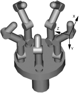
Figure 6.18. Coordinate definition of the robotic hand system.
Then the control law of PD controller can be defined as
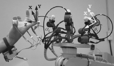
Figure 6.19. Configuration for robotic hand and MIDS.
where τi are the control torques for the five fingers, i = 1, …,5; j is the sequential variable; Pi = 20 are the position gains for the five fingers, i = 1, … ,5; and Di = 100 are the velocity gains for the five fingers, i = 1, … ,5.
The control torques τi are the input forces for the joint motors of the five robotic fingers. The joint torques are controlled to change the joint angle of each robotic finger. For the arm control of the robotic hand, the measured joint angles were directly sent to the robotic hand system. The robotic arm can then directly move to that angle without an extra control algorithm.
6.3.1.4 Experimental Results. Two experiments were performed to demonstrate the controllability of moving and grasping motions of the robotic hand manipulator. In the first experiment, the operator tried to perform the grasping motion by opening the hand and closing the hand periodically. The experiment was performed for four cycles within 10 sec. Experimental results for the grasping motion control are shown in Figure 6.20, where Finger 1 to Finger 5 are for thumb, index, middle, ring, and little fingers, respectively. The solid lines are the desired angles, which are the human finger angles measured by MIDS, for the control input. The lines with circle markers are the resultant joint angles of the robotic fingers, which are measured by the joint angle sensors inside the joints.
The process for this experiment is shown in Figure 6.21. First, both the human hand and the robotic hand were opened (Figure 6.21a). Then, the human fingers began to move toward a grasping motion, which was followed by the robotic hand (Figure 6.21b). Finally, the operator closed his hand and let the robotic hand followed this motion (Figure 6.21c) before he returned his fingers to their starting positions to perform the next grasping motion.
Comparing the results from MIDS and the sensors that were already on the robotic fingers, the desired angles for control input lead the resultant joint angles by about 0.3 sec, which is from the physical response times of the motors. Beside this time lag, the signal patterns of the finger joints are tracked to the operator's finger motion, which means that the robotic hand system can perform a good grasping motion by using MIDS to control them wirelessly.
In the second experiment, the operator tried to control the robotic hand to grasp a ball, which was located in a preset position. The experimental process is shown in Figure 6.22. The operator and the robotic hand were initially in start position (Figure 6.22a). Then the operator moved his hand, and the robotic hand followed this motion to move to the ball position (Figure 6.22b). The operator controlled the robotic hand to perform a grasping motion to grasp a ball and then held the ball moving back to the start position (Figure 6.22c and 6.22d). Then, the operator controlled the robotic hand back to the ball position and released the ball (Figure 6.22e). Finally, both the operator's hand and the robotic hand returned to the start position (Figure 6.22f). This test was performed to demonstrate that an operator could really control a robotic hand wireless to grasp and move an object using his own hand and arm motions.
The moving angle data from the second experiment are shown in Figure 6.23. The regions (a) to (f) in Figure 6.23, are the experimental results corresponding to the process states (a) to (f) in Figure 6.22. In the graph of Figure 6.23, the arm angle changed from 0rad to −3.14rad in region (a). This change means that the robotic hand changed from upward vertical orientation to downward orientation. In region (a), only the robotic arm moved, whereas all fingers did not move because the operator did not move his fingers. In region (b), the operator controlled the robotic finger to grasp a ball. The five fingers rotated from 0rad to −1.5rad. Similar to the first experiment, the MIDS command signals lead the robot finger signals by about 0.3 sec due to the physical response time of the joint motors. After that, the robotic hand held the ball and moved back to the starting position such that the arm angle changed from −3.14rad to 0rad in region (c). Then both the human hand and the robotic arm moved back to the ball position so the arm angle changed again from 0rad to −3.14rad [region (d)]. In region (e), the operator tried to control the robotic hand to release the ball; hence, the five fingers rotated from −1.5rad to 0rad. Finally, the arm angle changed back to the start orientation [from −3.14rad to 0rad (region (f)].
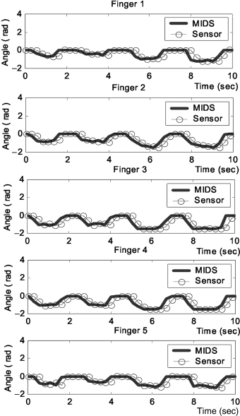
Figure 6.20. First experiment—angle data of five fingers from MIDS and joint angle sensors inside robotic hand system.

Figure 6.21. Process of grasping motion control of robotic hand system by MIDS.
6.3.2 Computer Mouse on a Fingertip (MIDS-VM)
The mouse is one of the most pervasive devices in our lives. A recent survey of 1000 Internet users, fielded for Logitech by Greenfield Online, found that 63% of respondents spent more time holding their mouse than any other commonly held objects, including cell phones, remote controls, steering wheels, PDAs, or their lovers. The same survey found that 26% of respondents felt the mouse was the most important device in the computing experience, second only to the monitor (named by 51% of respondents).

Figure 6.22. Process of controlling a robotic hand system to grasp a ball by MIDS.
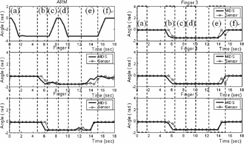
Figure 6.23. Second experiment—angle data from six MIDS sensors (five fingers and arm) and the joint angles sensors on the robotic fingers.
Our proposed system, called Micro Input Devices System-Virtual Mouse (MIDS-VM), is made by merging MEMS sensors and a mechanical button system (Figure 6.24). It can be made into a ring-shaped structure or into any other structural forms. There are two designs for MIDS-VM: 1) button system and 2) 3D system.
For the button system, one two-axis acceleration sensor is placed inside the housing on the finger of the user in order to measure the motion or orientation of the fingertip and two buttons are placed on the housing to provide left and right click buttons. For the 3D system, only one 3D acceleration sensor is placed inside the housing on the finger of the user in order to measure the 3D motion or orientation of the fingertip.

Figure 6.24. Configuration comparison between traditional input devices and a wireless MIDS.
For both designs, a microcontroller is used to process and analyze sensor signals. It can be connected to a computer directly (for wired system), or it can be connected to a transmitter for wireless transmission. For the wireless system, the receiver is connected to the computer. The motion-to-command algorithms can convert the motions of the user to input commands so MIDS-VM can function as a PC mouse such that it allows the user to move curser, perform the drag-and-drop motion, left and right click, as well as control the scroll bar on the desk or in mid-air. Also, this novel computer–human interface allows a user to use a ring-shaped input device to handle graphical user interfaces. The details of the MIDS-VM are presented in the following subsections.
6.3.2.1 System Configuration. Based on the MIDS technology, the MIDS-VM can be developed as wired and wireless systems. For both wired and wireless systems, the MIDS-VM includes the sensing unit, signal processing unit, interface unit, and driver interface program. As mentioned, the MIDS-VM is a ring-shaped system. The MIDS units will be allocated based on the mechanical design of the ring. The detailed system configuration is discussed below.
6.3.2.2 MIDS Wired Ring. In the MIDS-VM wired ring, the sensing unit includes the motion sensor and buttons that are used to measure the human motion and button input. Two buttons in the MIDS-VM function as left and right click buttons. The sensing unit is installed in the ring-shaped housing, which was made by a rapid prototyping machine (FDM1600 by StrataSys Inc.). The MEMS sensor on a ring is placed on a PCB containing signal conditioning circuits. The signals from the sensor and buttons are directly transferred to the signal processing unit while the power is supplied by the signal processing unit through the wire. The schematic diagram for a MIDS-VM wired ring is shown in Figure 6.25.
The signal processing unit is integrated with the hardware interface unit (serial connection or USB connection). The two units are installed in the connector housing. For the serial system, the battery is needed to provide power to the system. The command is transferred to the computer through the serial port. For the USB system, no battery is needed. The system can get the power directly from the computer, and the signal command is transferred to it through the USB port. When the driver interface program detects that the commands are received, it will generate the command message to the operation system of the computer.
The MIDS-VM wired ring prototypes (for serial and USB system) are shown in Figure 6.26 and 6.27. Note that the design of the rings for the serial and USB systems is different.
6.3.2.3 MIDS Wireless Ring. In the MIDS-VM wireless ring, the sensing unit also includes the motion sensor and buttons. The two buttons function as left- and right-click buttons. The sensing unit is directly connected to the signal processing unit with the hardware interface unit (wireless transmitter module), and these units are installed in the ring-shaped housing, which was made by a rapid prototyping machine (FDM1600 by StrataSys Inc.). The MEMS sensor on a ring, MCU, and RF transmitter are placed on a PCB containing signal conditioning circuits. The ring-shaped housing with the battery holder can carry the battery cell for supplying the power to the whole system. The schematic diagram for a MIDS-VM wired ring is shown in Figure 6.28. The entire MIDS-VM wireless ring prototypes are shown in Figures 6.29 and 6.30.
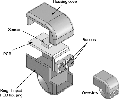
Figure 6.25. Schematic diagram of the MIDS-VM wired ring (two buttons).

Figure 6.26. Serial MIDS-VM wired ring (two buttons).
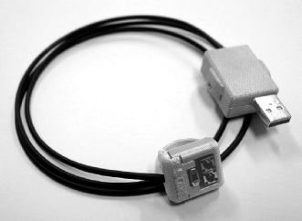
Figure 6.27. USB MIDS-VM wired ring (two buttons).
The hardware interface unit including the wireless RF receiver can be connected to the computer through a serial or USB connection (see Figures 6.31 and 6.32). Similar to the wired systems, a battery is needed to provide power to the serial system, but no battery is needed for the USB system. The signals received from the RF receiver are transferred to the driver interface program, and then the driver program will generate the command message to the operating system of the computer.
6.3.2.4 Mechanical Design. Use of a computer mouse is not necessarily benign. Evidence is suggesting that the prolonged use of a computer mouse is associated with several upper extremity musculoskeletal disorders.
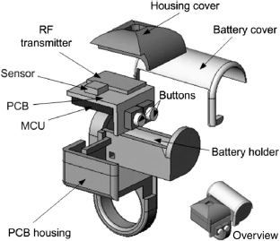
Figure 6.28. Schematic diagram of the MIDS-VM wireless ring (two buttons).
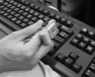
Figure 6.29. MIDS-VM wireless ring (side-button design).
As a human–machine interface, a good ergonomic design for MIDS is very important. There are two designs for the MIDS-VM mouse ring: side-button ring and top-button ring. The concept of side-button ring design is based on the direct pointing concept. People would like to point to the target with their finger. This side-button ring is convenient for directly pointing at the computer screen. However, it is not good in an ergonomic point of view. In the Figure 6.33, the force diagram of the side-button ring of MIDS-VM has been shown. To point to the target, the user needs to maintain the finger holding the ring horizontally (see Figure 6.33). Because of the weight of the ring and hand, the wrist has to pull the hand backward to balance the hand such that external force is needed. As a result, the user may feel tired when they use this side-button ring for a long time.

Figure 6.30. MIDS-VM wireless ring (top-button design).
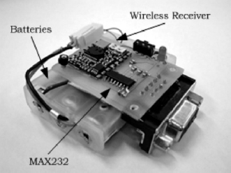
Figure 6.31. Prototype of serial receiver.
Because of the problems of the side-button ring, the top-button ring had been designed. It is also convenient for them to point to the computer screen, but it is not necessary for them to hold the finger horizontally. The user may keep the hand in a vertical position on the table; then the resultant force from the table support will directly balance out the weight of the ring and hand. No external force is needed to maintain the operation. As a result, the user can play with it for a much longer time than the side-button ring. The force diagram of the top-button ring is shown in Figure 6.34.
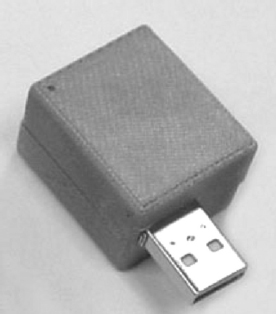
Figure 6.32. Prototype of USB receiver.
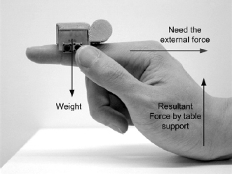
Figure 6.33. Force diagram of the side-button ring of MIDS-VM.
On the other hand, the ergonomic evaluation for button pressing has been conducted. The force diagrams for side-button ring and top-button ring are shown in Figures 6.35 and 6.36. It can be seen that the user tried to press the button on the side-button ring. A force was applied on the ring so that a force was needed against this force from the button pressing (see Figure 6.35). However, the user does not need to provide external force during the pressing of the button in the top-button ring because the resultant force from the table cancels out the force from button pressing. Therefore, the user can save energy by using the top-button ring, comparing it with the side-button ring.

Figure 6.34. Force diagram of the top-button ring of MIDS-VM.
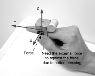
Figure 6.35. Force diagram for button pressing (side-button ring).
This ergonomic design of the top-button ring keeps the arm positioned for natural, comfortable movement, which has been clinically proven to be able to reduce muscle strain and discomfort associated with Carpal Tunnel Syndrome and repetitive stress injury, compared with the traditional mouse.
A pilot test has been conducted by the Sport and Physical Education Department of The Chinese University of Hong Kong. A female subject used a keyboard and MIDS-VM to play a computer game for around 1 hour. From the result of trend comparison, the muscle activities of the subject were larger when using the keyboard to perform the selected game task at flexor carpi ulnaris, extensor carpi ulnaris, and trapezius 1. Muscle fatigues might occur at flexor carpi ulnaris, trapezius 1, and trapezius 4 after 50 minutes. Although the sample size is too small, this pilot test can basically reflect that using MIDS-VM would be potentially better than the traditional input devices like the keyboard.
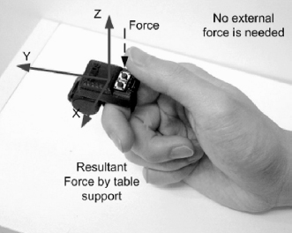
Figure 6.36. Force diagram for button pressing (top-button ring).
6.3.2.5 Theory of Motion-to-Command Algorithm. The working principle of MIDS-VM is based on the rotation of the user's finger/wrist. The motion-to-command algorithm of MIDS-VM is the conversion of tilt and roll angle to x and y movement on the screen (i.e., a mapping for rotation to linear movement). The consideration of this algorithm is to provide a smooth, easy-to-learn, and effective operation method to users. To achieve this goal, a nonlinear equation for rotation-to-linear motion has been developed.
where Dn is the current movement (in pixel); Dn−1 is the previous movement (in pixel); a, b, and c are the scaling factors. P1 and P2 are the power indices, and S1 and S2 are the scaling factors for the history data.
To make it easy to control, the algorithm should allow slight movement during the first period of time. In this study, we assumed the movement has not been too large in the first 0.6 sec such that the maximum movement should not exceed 200 pixels (which is about 25% of the width of a 800 × 600 screen size).
It is necessary to set an upper bound for the movement of the mouse cursor to avoid the “disappearance” of the cursor. Thus, the maximum movement has been set to prevent the cursor from moving too fast:
There are three constraints for setting the parameters:
- At 0.5 sec, the mouse cursor movement should not exceed 200 pixels (in order to keep the motion slow and smooth for precise control).
- From 0.5 sec to 1 sec, the mouse cursor movement should reach the maximum speed to provide a fast response.
- At 1 sec, the mouse cursor should be moved around 800 pixels (assume 800 pixels is the maximum distance in a 800 × 600 screen size) such that the maximum speed or upper bound of the mouse movement is set to keep fast travel as well as to make the move visible.
By trial-and-error parameter setting, the parameters of the MIDS-VM motion-to-command algorithm are determined for fulfilling the constraints of the mouse movement. The values of the parameters are shown in Table 6.2.
Table 6.2. Parameters of MIDS-VM Motion-to-Command Algorithm

Using the above parameter setting, the experiments were conducted to evaluate the movement of MIDS-VM. In Figure 6.37, the mouse movement operated by MIDS-VM has been shown. The mouse movement before 0.5 sec did not exceed 200 pixels, whereas the mouse can move up to around 800 pixels in 1 sec. The command for the mouse movement by MIDS is shown in Figure 6.38. The command reached the upper bound (20 pixels) after 0.5 sec in order to provide the maximum speed for the mouse movement. This experimental data show that the mouse movement is in an exponential curve to maintain the small movement at the first 0.5 sec (for precise control) and to provide large movement for fast mouse control after 0.5 sec.
6.3.2.6 Working Principle. To maintain the consistency of the MIDS products, the working principles for wired and wireless rings are the same. Based on the MIDS-tech mentioned, the data format is set to 3 bytes of data. The start byte is 255 to 252. The meanings of the start bye values can be found in Table 6.3. It has been set such that the final two bytes cannot be larger than 252. Thus, the acceleration value range in x- and y-direction is 0 to 251. Note that the acceleration is T1/T2, which is the ratio of the period of HIGH to the duty cycle. The actual value of the acceleration will be translated in the MIDS driver interface.

Figure 6.37. Mouse cursor movement operated by the MIDS-VM.

Figure 6.38. Command for the mouse movement by MIDS-VM.
Since the MIDS-VM is based on the rotation of the user's finger/wrist (see Figure 6.39), the acceleration ranges from −g to g such that the range of the output values, Yout and Xout, is 0 to 251. Zero gravity is represented by Aout = 126. The sequence of the output value, Aout, of the MIDS-VM is shown in Figure 6.40.
With the above output sequence, the driver interface receives the data through either the wired or the wireless receiver connected to the serial/USB port. Then the driver interface recognizes the start byte first (to check Aout > 251, if yes, then it is start byte) and classifies the button-pressing status based on Table 6.3. The following byte is stored in the variable Yout, and the next byte is stored in Xout. After receiving those data, they are passed to the motion-to-command algorithm to generate the commands. The details of the motion-to-command algorithm will be presented in the following section. The working principle is shown in Figure 6.41. When the MIDS mouse ring is rotated clockwise about the y-axis (the acceleration value Yout > 126), it is recognized as the “move cursor right” action. If it is rotated anti-clockwise (the acceleration value Yout < 126), it is recognized as the “move cursor left” action. Similarly, it is recognized as the “move cursor up” action when the MIDS mouse ring is rotated clockwise about the x-axis (the acceleration value Xout > 126). If rotated anti-clockwise (the acceleration value Xout < 126), it is recognized as the “move cursor down” action (see Figure 6.42 and Tables 6.4–6.6).
Table 6.3. Meanings for Start Byte Values
| Start Byte Values | Value Meaning |
| 255 | No button has been pressed |
| 254 | Left button has been pressed |
| 253 | Right button has been pressed |
| 252 | Two button have been pressed |
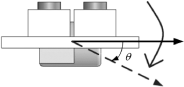
Figure 6.39. Working principle for MIDS-VM—Rotation of user7's finger or wrist.

Figure 6.40. Output sequence of the MIDS-VM.
6.3.3 Computer Game Interaction Using MIDS
The realism and sophistication of computer games continue to increase as computer hardware becomes less expensive. New features for games nowadays are realistic 3D scenes and live-like sounds. In addition, low-cost head-mounted displays will soon be available and will make truly immersive virtual reality experiences affordable in the near future. Both the gaming industry and users have become intrigued by 3D graphics technology, and a number of game software developers agree that the 3D graphics performance in mobile phones has finally surpassed that of the Game Boy Advance [14].

Figure 6.41. Working principle of the MIDS-VM.
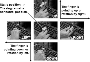
Figure 6.42. Demonstration for MIDS-VM.
Mobile phones are not the only platform. In fact, a variety of other products are being announced. The N-Gage from Nokia Corp of Finland [15], and the Zodiac from Tapwave Inc. of the United States all offer high-performance 3D graphics [16]. Around the end of 2004, Sony Computer Entertainment Inc. (SCE) of Japan released the PlayStation® Portable (PSP) [17], with a peak performance of 3.3 M-polygons/sec. While providing only half the 6.6 M-polygons/sec of the PlayStation®2, it still represented a stunning improvement over the first-generation PlayStation®.
Table 6.4. Technical Data of Wireless MIDS Mouse Ring
| E-MIDS Acceleration Range (1 g = 9.81ms−2) | ±2g |
| Acceleration resolution | 5 mg |
| Angle range | −0° to 360° |
| Angle resolution | 1° ± 0.4° |
| Data sampling frequency | 70Hz |
| Command transmission rate | 2400 bit/sec |
| Supply current | ~8mA |
| Operating voltage | 3V |
| Power consumption | ~24mW |
Table 6.5. Technical Data of Wireless MIDS Receiver Interface

Table 6.6. Technical Data of Wired MIDS Mouse Ring
| Acceleration Range (1 g = 9.81ms−2) | ± 2g |
| Acceleration resolution | 5mg |
| Angle range | −0° to 360° |
| Angle resolution | $1 ± 0.4° |
| Data sampling frequency | 150 Hz |
| Command transmission rate | 9600 bit/sec |
| Supply current | ~30 mA |
| Operating voltage | 5 V |
| Power consumption | ~150 mW$ |
To complement this trend, new input devices will be needed to improve the realism of the gaming experience. A standard joystick may no longer be an acceptable substitute for a gun, sword, fist, or steering wheel. Essential Reality is developing a new generation of product called P5 that enables the interface between human and machine in video gaming applications [18]. The P5 is a glove-like peripheral device based on proprietary bend sensor and remote tracking technologies that provides users with intuitive interaction with 3D and virtual games.
Using MIDS technology, a multifunctional controller can be developed. The same module can be applied to the control of PDAs and mobile phones gaming by the usage of a GUI. The idea of this multifunctional game controller is to make use of a motion sensing module with a microcontroller as a center control unit that is allowed to plug-in into different plastic housings to emulate different applications such as a joystick, gun, joy-pad, racing wheel, and others yet to be developed. This concept is illustrated in Figure 6.43.
6.3.3.1 System Configuration. The system requirement for gaming application is very high. Sensitivity, functions, and quality of the usage have to keep in high performance. As a new motion-based controller, more functions are needed. Based on the MIDS technology, the hardware for this game controller is similar to the MIDS-VM ring, but more buttons are added, and the driver and the GUI are modified specifically for the game application.
6.3.3.2 4-button MIDS Game Controller Ring (MIDS-GC ring). A four-button wired MIDS ring is designed with game control functions. The sensing unit includes the motion sensor and buttons that are used to measure the human motion and button input. Four buttons in the ring function as mouse buttons and/or keyboard buttons. The sensing unit is installed in the ring-shaped housing, which was made by a rapid prototyping machine (FDM1600 by StrataSys Inc.). The MEMS sensor on a ring is placed on a PCB containing signal conditioning circuits. The signals from the sensor and buttons are directly transferred to the signal processing unit, whereas the power is supplied by the signal processing unit through the wire. The signal processing unit is integrated with the USB interface unit. The driver interface program has to be installed in the computer, which is used to receive the motion signal to and convert the command message to the operating system of the computer. The prototype of a four-button MIDS wired ring is shown in Figure 6.44.
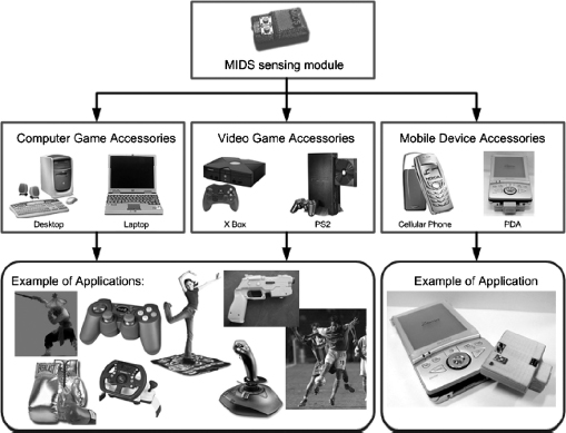
Figure 6.43. MIDS motion-based controllers for different gaming applications.
6.3.3.3 Gaming Platforms. Two commercial computer game platforms are selected to demonstrate the functions of the MIDS-GC ring. Tom Clancy's Rainbow SixTM 3 – Raven Shield is a famous computer shooting game that required both a mouse and a keyboard to play. As a MIDS-GC ring can provide mouse and keyboard control, a user can just use one input device to play with this game.
Team17's Stunt GP is a nice 3D PC racing game that only required a keyboard to play. However, users always prefer to use the racing wheel because they will enjoy the game more (more like driving). A MIDS-GC ring can provide such a feature based on the similar operation principle of the driving wheel. A MIDS-GC can convert the motion and button input into the keyboard command so that user can drive the virtual racing car by rotating their hand. The function of the MIDS-GC ring is shown in Figure 6.45 and Table 6.7.

Figure 6.44. Function description of a four-button wired MIDS game controller ring.
6.3.3.4 Theory of Motion-to-Command Algorithm. The motion-to-command algorithm for MIDS-GC is same as MIDS-VM but with more functions because more buttons are added (Figure 6.46 and 6.47). The MIDS-GC user configuration interface allows the user to select the function for different motions. Mouse and keyboard functions are allowed to be selected.
6.3.3.5 Working Principle. The detail description for demonstrating the operation of an MIDS-GC ring for the game Stunt GP is shown below:
- Turns left and right by hand motion (see Figure 6.48)
- Other functions such as move forward, move backward, turbo accelerate, and enter are accessed by pressing the corresponding buttons on the MIDS racing ring.
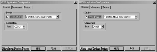
Figure 6.45. MIDS multifunction interface for two- and four-button ring.
Table 6.7. Technical Data of Wireless Game Controller Ring
| E-MIDS Acceleration Range (1 g = 9.81ms−2) | ± 2g |
| Acceleration resolution | 5mg |
| Angle range | −0° to 360° |
| Angle resolution | 1° ± 0.4° |
| Data sampling frequency | 150Hz |
| Command transmission rate | 2400bit/sec |
| Supply current | ~10mA |
| Operating voltage | 3V |
| Power consumption | ~30mW |
6.3.4 MIDS for PDA Interaction (Embedded-MIDS: E-MIDS)
Besides the desktop and laptop computer, mobile computers are developing rapidly. Many people want to have a tiny device like a digital organizer to help them to manage the personal data. In addition, people start to think of playing mobile games. With the advances of technologies in mobile phones and personal digital assistants (PDAs), more and more mobile devices can be used to play games. Thus, user-friendly input devices, which are also convenient to use on a mobile platform, are very important for playing games on PDAs or mobile phones. As a game controller, the system requirement (high sensitivity and user-friendly control, etc.) is much higher than other input devices. A novel mobile input device or game controller will potentially drive the game development for mobile devices. Various input devices (such as joystick, joy pad, and racing wheel) other than a traditional mouse and keyboard have been already developed for desktop computers.

Figure 6.46. MIDS interface for motion settings.
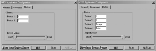
Figure 6.47. MIDS interface for button function selection.

Figure 6.48. To rotate the MIDS mouse ring in an anticlockwise direction.
However, the most common input devices for PDAs are still stylus and keypad. They have survived without significant changes even though the PDAs have already evolved several generations. Stylus is small in size and easy to carry. Nevertheless, it may destroy the touch screen easily, especially by users who are overly excited while playing games. To protect the screen, a stylus-like product, Magic Finger [19], is available on the market. Magic finger is a rubber pack that is worn on the finger and allows users to point at the screen. Although it can prevent the damage of the screen, it is obviously not suitable for game playing. For some games such as role-play games (RPG), stylus and magic finger are also not suitable to navigate the character around the environment because the users' fingers will block the screen, which will cause an inconvenience while controlling the game. Moreover, such input devices are too simple and have limited functions. Thus, game developers are currently constrained by the stylus in creating games for mobile devices.
Many mobile games use keys as controllers. However, because of the compact size of the PDAs, the build-in keys are always very small and difficult to access. To tackle this problem, manufacturers have tried to minimize the external keyboard size and develop many compact products such as wireless keyboards [20] or folding keyboards [21]. However, it is still a burden for the users to carry it around. (Normally, the external keyboards are the same size as a PDA.) Furthermore, it is inconvenient for users to play games with external keyboards on a bus or walking on a street.
Besides the above disadvantages of existing input devices for mobile products, the users usually cannot fully enjoy the games. Many games such as action games and sports games could be much more exciting if the players can use their body motion. This is the reason why many people are crazy about playing virtual reality games.
On the other hand, the functionality of mobile phones and PDAs is ever increasing while their size is ever decreasing. These trends will limit the usability of the devices if traditional user interfaces such as buttons and jog dials are not replaced by the next generation of “natural” user interfaces such as speech and motion. Considering the needs of the mobile devices, a novel controller called E-MIDS has been invented to take advantage of the human mobility as well as motion capturing for game control. In addition, it is a small-size, easy-to-carry, user-friendly, and multifunctional controller that is suitable for mobile devices (the external device is just one third the size of a PDA). Moreover, E-MIDS can be either plugged-in or embedded into mobile devices such as mobile phones and PDAs, or by replacing their existing housing structure. The conceptual system configuration of E-MIDS for mobile devices is shown in Figure 6.49.
With the embedded feature, users just need to take care of the PDAs and there is no need to carry any other external devices. As the users only have to move or rotate their PDAs to control the game, it will not damage any parts (such as the screen) of the PDAs. Most importantly, it provides a way for the users to control the games with their body motion, and lets the users enjoy the games more. The comparison between E-MIDS and existing input devices for PDAs is shown in Table 6.8.
Based on MIDS technology, E-MIDS is invented that can be externally connected to or internally embedded in mobile devices such as PDAs or cellular phones. For external E-MIDS, it can be connected to mobile devices through the serial port or USB port. For internal E-MIDS, it is embedded inside the mobile devices, which means that E-MIDS will not be shown to users. Using E-MIDS, the users can use their motion as an input method to play or control the mobile games. For these two systems, E-MIDS can get the power supply from the mobile devices directly. In the coming sections, the demonstration for an external E-MIDS connected to the PDA, Sharp Zaurus, will be illustrated.
6.3.4.1 System Configuration. For the demonstration of using E-MIDS to control a mobile device, the targeted mobile device is the PDA Zaurus SL5500 manufactured by Sharp. The game control realized for this demonstration system is “Aliens.”
The system configuration and the prototype of E-MIDS are shown in Figure 6.50. There is a dual-axis MEMS sensor (the sensing unit) that is used to measure the human motion. In addition, there are two buttons on the PCB. The users can play games not only with their motions, but also with the traditional method of pressing buttons.
Since E-MIDS is connected to the PDA externally as is shown in Figure 6.51, the sensor can measure the motion of the PDA when the user is holding it. The MCU (the signal processing unit) will get the input data both from the sensor and the buttons and then it will process the signal. Through the motion-to-command algorithm, the motion signals will be converted to command signals. After that, the commands will be converted to serial format by the RS232 chip. Finally, the serial format commands will be sent to the PDA to control the game. The data flow of E-MIDS is shown in Figure 6.52.
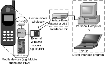
Figure 6.49. The conceptual system configuration of E-MIDS for mobile devices.
In this work, the Sharp Zaurus SL5500 is selected as the host device in the demonstration. This system provides a serial/USB IO port at the bottom part of it as shown in Figure 6.51. For the hardware configuration, the serial connecter of the E-MIDS is connected to the Zaurus IO port. For the software driver, the Zaurus (the operating system is Linux) is booted in “INIT 3” mode to activate the serial function of the Zaurus's IO port, which can be accessed via “/dev/ttyS0.”
6.3.4.2 Theory of Motion-to-Command Algorithm. The program flow of most games for Zaurus is shown in Figure 6.53. A top-level class is instantiated at the beginning of the game and handles the game and display control. To allow E-MIDS to directly control games hosted on the Zaurus, a mechanism is added to read the E-MIDS input signals, and then to pass it to the data handling routine. The data handling routine can further interpret the signals according to the game semantics, and then it generates the corresponding game commands. This mechanism is added to the top-level class. Thus E-MIDS can control the game via this top-level class and game designers need not modify the implementation of the game. This motion-to-command algorithm in the game “Aliens” is shown in Figure 6.54.
Table 6.8. Comparison Between E-MIDS and Existing Input Devices for PDAs
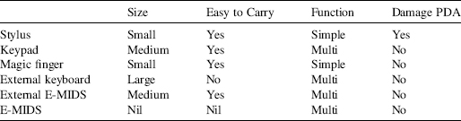

Figure 6.50. Schematic and prototype of E-MIDS.
In Figure 6.55, the black dotted line is the motion-to-command algorithm of E-MIDS added to the original “Aliens” game program flow. The data handling is event driven. At the start of the game, the serial port “dev/ttyS0” is opened and configured to receive the E-MIDS signals. Then a socket notifier [22] is created and bounded to it. The socket notifier will notify the data handling routine when the data from E-MIDS are received. In the data handling routine, the validity of the data is checked first. The data are further interpreted only when it is correct. The E-MIDS signals consist of motion information as well as the E-MIDS button status. They are handled separately.
6.3.4.3 Working Principle. The motion information, which is measured by the E-MIDS sensor, is converted to the pitch angle θ. The pitch angle (the range is from −90° to 90°) of the E-MIDS is relative to the world coordinate frame as shown in Figure 6.55. Based on the angle θ, the rotational motion of the user's hand can be inferred so that the command for the game control can be defined as listed in Table 6.9. According to the results of trial-and-error testing, the threshold region is defined between −7° to 7°. When the θ is within this region, the PDA is regarded as stationary in order to ignore the users' hand shaking. In the original “Aliens” game, the “LEFT” and “RIGHT” direction keys are used to move the spaceship leftward and rightward, respectively. Therefore, when the pitch angle θ is between −90° and −7° (the user rotated the PDA counterclockwise by θ), a left key pressed event is sent to the top-level class to move the spaceship to left. Similarly, when the pitch angle θ is between 7° and 90° (the user rotated the PDA clockwise by θ), a right key pressed event is sent to move the spaceship to the right.
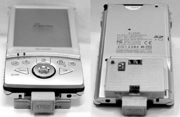
Figure 6.51. Installation of E-MIDS for a Sharp PDA.
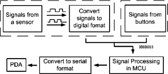
Figure 6.52. Data flowchart of E-MIDS.
On the other hand, the spacebar is used to fire. Thus a space key pressed event is sent to activate the fire function when a button click action (E-MIDS buttons) is received.
Note that the E-MIDS motion-to-command algorithm (see Figure 6.54, the black dotted line) is a module added to the original program flow. It does not affect the performance of the original game design. This module feature can provide an easy way for the game designer to use the E-MIDS as a game controller because this motion-to-command algorithm can be separately developed by just knowing how to play the game and there is no need to study the details of the game implementation.

Figure 6.53. Program flow of Zaurus games.

Figure 6.54. Program flow of “Aliens” with E-MIDS motion-to-command algorithm.
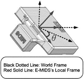
Figure 6.55. Coordinate frame of the E-MIDS.
Table 6.9. Illustration of Motion-to-Command Algorithm

The demonstration of playing the “Aliens” with E-MIDS is shown in Figure 6.56. When the user rotates the PDA in a clockwise direction, the spaceship will move leftward as in Figure 6.57. Similarly, when the user rotates the PDA in counterclockwise direction, the spaceship will move rightward. There is no denying that “Aliens” will become more entertaining compared with key-controlled “Aliens” (which keeps the players busy pressing buttons on the small keypad on the PDA) and stylus-controlled “Aliens” (which not only keeps the players tracking the spaceship but also causes much confusion and many mistakes). Therefore, E-MIDS can make the control of the “Aliens” become more direct by using the hand motion.
The performances of E-MIDS and traditional input devices in playing “Aliens” are evaluated and compared. The transmission rate of E-MIDS data to Zaurus is around 70 commands per second. It means that the sensitivity is high enough to measure the human hand motion (normally the rate of human hand motion is less than 10 Hz without considering the hand shaking). Therefore, E-MIDS can respond fast enough to human motion. As a result, the factor that affects the performance of E-MIDS and traditional input devices in playing a game is the user's habit, which is how fast the user can input commands with those devices.
An experiment is designed and carried out to measure the user's habit of using E-MIDS and traditional input devices in playing “Aliens.” There are three commands to “Aliens”: move left, move right, and fire. For the fire command, E-MIDS is based on button pressing, whereas traditional input devices are just based on key pressing such that they make no differences. Thus, only the move left and right commands need to be investigated. To get how fast the user inputs commands, the time when the user inputs each command has to be recorded. As shown in Figure 6.58, an additional block is inserted into the game flow to record the time of a user's input command.
An experienced user was invited to play “Aliens” with both E-MIDS and traditional input devices. He was asked to generate move left and right commands alternatively as fast as he can by using E-MIDS, keypad, and stylus, respectively. For E-MIDS, the user rotated the PDA by his wrist to generate game commands. For keypad, the user pressed the left and right keys with thumb. For stylus, the user pointed to the left side of the spaceship to move it left and pointed to the right side to move it right. In each experiment, the time for input generation and the number of input cycle are recorded for 1 minute (60 sec).
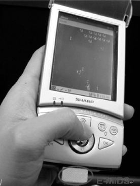
Figure 6.56. Demonstration of “Aliens” with E-MIDS.
The total numbers of input cycles in 1 minute for three input devices are listed in Table 6.10. The user using E-MIDS can generate game commands two times faster than using a keypad, and almost three times faster than using a stylus. As described before, the threshold region for the pitch angle q is defined between −7° and 7° to ignore a user's hand shaking, and this threshold has been experimentally proved to be able to eliminate most hand shaking. However, the setting of the threshold region reduced the sensitivity of the control. Fortunately, the results of this experiment show that the response of control is faster than that of the traditional input devices. It means that E-MIDS can provide faster response time and eliminate the error from hand shaking. Based on the experimental results of the above experiment, the frequency response of each input method is further investigated.
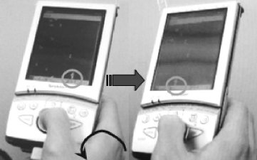
Figure 6.57. Rotating the PDA counterclockwise.
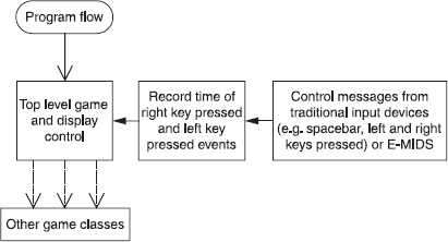
Figure 6.58. Program flow to capture command time.
The frequency response measurement is based on the power spectrum density (PSB) of the input rates by using E-MIDS, keypad, and stylus (see Figure 6.59). The PSD of the input rates of different input devices shows the dominating frequency (peak rate) for E-MIDS is 3.52 Hz, whereas the dominating frequencies for keypad and stylus are 1.95 Hz and 1.56 Hz, respectively. The components of E-MIDS induced by hand shaking are always of high frequency if there are any. Therefore the peak rate 3.52 Hz can more accurately reflect the user's intentional hand motion. This frequency response further proved that with E-MIDS the user can generate a higher frequency of input commands.
According to the experimental results, E-MIDS can provide a fast response for generating input commands that is two times faster than the traditional input devices. From the demonstration, E-MIDS is proved to be stable, controllable, easy-to-use, and user-friendly, which totally fulfilled the requirements of mobile-based gaming and is more suitable than the existing input devices for the mobile products. With E-MIDS, a new generation of mobile games will come in the near future because E-MIDS can provide more functions and higher flexibility for game designers (Table 6.11).
Table 6.10. Total Number of Input Cycles in 1 minute
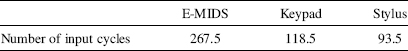

Figure 6.59. PSD of input rates by using E-MIDS, keypad, and stylus.
6.4 CONCLUSION
In this chapter, a novel MIDS technology is invented and it is a mature technology that makes use of human motion as a control methodology to develop different novel systems for computer input devices, motion sensing devices, and motion-based controllers. A series of workable system designs and algorithm/software developments for the human–robot–hand interaction system, fingertip computer mouse, ring-shaped game controller, and PDA controller are achieved.
With MIDS technology, a new generation of computer control style will come in the near future. You can imagine that the monitor can combine with the computer processor such that it is wearable (or just like glasses). This computer with MIDS can let users work everywhere when they are available. That means the office can be anywhere and that any time can be a working hour. It may bring us the revolution in computer development and human–machine interface. Therefore, it is concluded that this novel MIDS technology has the potential to give a deep positive impact to us in daily life. Besides the applications of MIDS mentioned above (such as computer input device, motion sensing device, and robot control device), there are many potential applications for this invention. Piano players can use the MIDS to play a virtual piano. Their piano keyboard input patterns can be transferred to the computer, which could be used for song recording or live-performance. Another application is that users can use the MIDS to interface with a PC using conventional sign-language gestures; i.e., users can simply use sign-language motions, and the computer will be able to translate the motions into sentences without any keyboard typing. One of the most meaningful applications for the MIDS will be its usefulness to help the blind. MIDS can help blind people to make brail-based typing by using different finger motion patterns. When the finger motion patterns are transferred to the computer, the computer can translate them to words and then save the words as a document. Other applications for the MIDS will include emulation of a laser-pointer, and as a light pen for languages such as Chinese.
Table 6.11. Technical Data of the E-MIDS
| E-MIDS Acceleration Range (1 g = 9.81 ms−2) | ± 2g |
| Acceleration resolution | 5mg |
| Angle range | −90° to 90° |
| Angle resolution | 1° ± 0.4° |
| Data sampling frequency | 70Hz |
| Command transmission rate | 2400bit/sec |
| Supply current | ~7mA |
| Operating voltage | 3V |
| Power consumption | ~20mW |
Actually, MIDS technology can be applied on all areas related to motion. Anyone may think of hundreds of applications using MIDS. The objective of this chapter is to introduce the fundamental knowledge of MIDS technology and provide an alternative for the people who want to make use of the human motion as a control method or to build an effective motion sensing system for motion measurement.
REFERENCES
1. Maxim Integrated Products Inc..: http://www.maxim-ic.com/
2. Future Technology Devices International Limited: http://www.ftdichip.com.
3. Analog device: http://www.analog.com.
4. Memsic: http://www.memsic.com/.
5. STMicroelectronics: http://www.st.com/.
6. S. M. Sze, Semiconductor Sensors, Hoboken, NJ, Wiley-Interscience, 1994.
7. Atmel Corporation: http://www.atmel.com/.
8. Linx Technologies: http://www.linxtechnologies.com/.
9. ASIMO: http://world.honda.com/ASIMO/.
10. Sony QRIO Robot: http://www.sony.net/SonyInfo/QRIO/top_nf.html.
11. D. Ding, Y.-H. Liu, J. Zhang, and A. Knoll, “Computation of fingertip positions for a form-closure grasp,” in Proc. of 2001 IEEE International Conference on Robotics and Automation, May 2001, Vol. 3, pp. 2217–2222.
12. Y. Hasegawa, J. Matsuno, and T. Fukuda, “Regrasping behavior generation for rectangular solid object,” in Proc. of 2000 IEEE International Conference on Robotics and Automation, April 2000, Vol. 4, pp. 3567–3572.
13. C.C. Cheah, H.Y. Han, S. Kawamura, and S. Arimoto, “Grasping and position control for multi-fingered robot hands with uncertain Jacobian matrices,” in Proc. of 1998 IEEE International Conference on Robotics and Automation, May 1998, Vol. 3, pp. 2403–2408.
14. Gameboy Advance: http://www.gameboy.com/.
15. Nokia's N-Gage: http://www.n-gage.com/.
16. Tapwave's Zodiac: http://www.tapwave.com/.
17. Sony's Playstation Portable: http://www.theregister.co.uk/2003/11/05/sony_playstation_portable_pics_pop/.
18. Essential Reality: http://www.essentialreality.com.
19. Kirrio Magic Finger: http://www.bargainpda.com/price/default.asp?productID=380&brandName=Kirrio&productName=Magic+Finger&display=productDetail.
20. PalmOne Infrared Wireless Keyboard for Palm PDAs – Palm Electronics: http://www.boondocksnet.com/cb/apfh-item_id-B0000E0ZY9-search_type-AsinSearch-locale-us.html.
21. Viewsonic Pocket PC V35 Foldable Keyboar, PPC-KYB-001, PPCKYB001: http://www.wholesalers-direct.com/ppckyb001.html.
22. Qt Toolkit – QSocketNotifier Class: http://doc.trolltech.com/qtopia1.6/html/qsocketnotifier.html.
Intelligent Wearable Interfaces, by Yangsheng Xu, Wen J. Li, and Ka Keung C. Lee
Copyright © 2008 John Wiley & Sons, Inc.