

Virtual Storage Console 4.1
The ability to quickly back up tens of hundreds of virtual machines without affecting production operations can accelerate the adoption of VMware within an organization, as explained in this chapter. It includes the following topics:
15.1 Virtual Storage Console
The Virtual Storage Console (VSC) feature was formerly provided in a separate interface and was called SnapManager for Virtual Infrastructure (SMVI). It builds on the N series SnapManager portfolio by providing array-based backups. They consume only block-level changes to each VM and can provide multiple recovery points throughout the day. The backups are an integrated component within the storage array. Therefore, VSC provides recovery times that are faster than times provided by any other means.
15.1.1 Introduction to the Virtual Storage Console
The Virtual Storage Console (VSC) software is a single vCenter Server plug-in. It provides end-to-end virtual machine lifecycle management for VMware environments running N series storage. The plug-in provides these features:
•Storage configuration and monitoring, using the Monitoring and Host Configuration capability (previously called the Virtual Storage Console capability)
•Datastore provisioning and virtual machine cloning, using the Provisioning and Cloning capability
•Backup and recovery of virtual machines and datastores, using the Backup and Recovery capability
As a vCenter Server plug-in, shown in Figure 15-1, the VSC is available to all vSphere Clients that connect to the vCenter Server. This availability is different from a client-side plug-in that must be installed on every vSphere Client. You can install the VSC software on a Windows server in your data center, but you must not install it on a client computer.
Figure 15-1 Virtual Storage Console
Virtual Storage Console (VSC) integrates VSC storage discovery, health monitoring, capacity management, and best practice-based storage setting. It offers additional management capabilities with two capability options in a single vSphere client plug-in. Thus it enables centralized, end-to-end management of virtual server and desktop environments running on N series storage. VSC is composed of three main components:
•Virtual Storage Console Capability (base product): Provides a storage view of the VMware environment with a VM administrator perspective. It automatically optimizes the customer’s host and storage configurations, including HBA timeouts, NFS tunables, and multipath configurations. Using the Virtual Storage Console, a VM administrator can quickly and easily view controller status and capacity information. Also, the administrator can accurately report back utilization information in order to make more informed decisions about VM object placement.
•Provisioning and Cloning Capability: Provides end-to-end datastore management (provisioning, resizing, and deletion). Also offers rapid, space-efficient VM server and desktop cloning, patching, and updating by using FlexClone technology.
•Backup and Recovery capability (formerly SnapManager for Virtual Infrastructure): Automates data protection processes by enabling VMware administrators to centrally manage backup and recovery of datastores and VMs. This can be done without impacting guest performance. The administrator can also rapidly recover from these backup copies at any level of granularity: datastore, VM, VMDK, or guest file.
VSC is designed to simplify storage management operations, improve efficiencies, enhance availability, and reduce storage costs in both SAN- and NAS-based VMware infrastructures.
It provides VMware administrators with a window into the storage domain. It also provides the tools to effectively and efficiently manage the lifecycle of virtual server and desktop environments running on N series storage.
It provides VMware administrators with a window into the storage domain. It also provides the tools to effectively and efficiently manage the lifecycle of virtual server and desktop environments running on N series storage.
15.1.2 License requirements
Table 15-1 summarizes the N series license requirements to perform different VSC functions.
Table 15-1 VSC license requirements
|
Task
|
License
|
|
Provision datastores
|
NFS, FCP, iSCSI
|
|
Restore datastores
|
SnapRestore
|
|
Use vFilers in Provisioning and Cloning operations
|
MultiStore
|
|
Clone virtual machines
|
FlexClone (NFS only)
|
|
Configure deduplication settings
|
A-SIS
|
|
Distribute templates to remote vCenters
|
SnapMirror
|
15.1.3 Architecture overview
Figure 15-2 illustrates the architecture for VSC. It also shows the components that work together to provide a comprehensive and powerful backup and recovery solution for VMware vSphere environments.
Figure 15-2 Architecture overview
15.1.4 Monitoring and host configuration
The Monitoring and Host Configuration capability enables you to manage ESXi servers connected to N series storage systems. You can set host timeout, NAS, and multipathing values, view storage details, and collect diagnostic data. You can use this capability to do the following tasks:
•View the status of storage controllers from a SAN (FC, FCoE, and iSCSI) perspective
•View the status of storage controllers from a NAS (NFS) perspective
•View SAN and NAS datastore capacity utilization
•View the status of VMware vStorage APIs for Array Integration (VAAI) support in the storage controller
•View the status of ESX hosts, including ESX version and overall status
•Check at a glance whether the following settings are configured correctly, and if not, automatically set the correct values:
– Storage adapter timeouts
– Multipathing settings
– NFS settings
•Set credentials to access storage controllers
•Launch the vCenter GUI to create LUNs and manage storage controllers
•Collect diagnostic information from the ESXi hosts, storage controllers, and Fibre Channel switches
•Access tools to set guest operating system timeouts and to identify and correct misaligned disk partitions
When you click the N series tab in the vCenter Server and click Monitoring and Host Configuration in the navigation pane, the Overview panel displays. It is similar to Figure 15-3.
Figure 15-3 VSC overview
Alternatively, you can find the VSC plug-in under Solutions and Applications (Figure 15-4).

Figure 15-4 VSC location
15.1.5 Provisioning and cloning
The Provisioning and Cloning capability of Virtual Storage Console helps you to provision datastores and quickly create multiple clones of virtual machines in the VMware environment. Using FlexClone technology, the Provisioning and Cloning capability allows you to efficiently create, deploy, and manage the lifecycle of virtual machines. These tasks can be done from an easy-to-use interface integrated into the VMware environment. It is ideal for virtual server, desktop, and cloud environments.
You can use the provisioning and cloning capability for the following purposes:
•Clone individual virtual machines and place in new or existing datastores
•Create, resize, or delete datastores
•Apply guest customization specifications and power up new virtual machines
•Run deduplication operations
•Monitor storage savings
•Redeploy virtual machines from a baseline image
•Replicate NFS datastores across sites
•Import virtual machines into virtual desktop infrastructure connection brokers and management tools
Managing datastores and cloning virtual machines
To manage datastores and clone virtual machines, right-click an object in the Inventory panel of the vSphere Client and select IBM N series → Provisioning and Cloning (Figure 15-5):
•Right-click a powered-down virtual machine or template to create clones.
•Right-click a datacenter, cluster, or host to provision datastores.

Figure 15-5 Accessing Provisioning and Cloning
Managing controllers, replicating datastores, and redeploying clones
Click the Inventory button in the navigation bar, and then select Solutions and Applications → IBM N series → Provisioning and Cloning. Use the following options:
•Select Storage controllers to add, remove, or modify properties of storage controllers.
•Select Connection brokers to add and remove connection broker definitions.
•Select DS Remote Replication to clone NFS datastore templates to multiple target sites.
•Select Redeploy to redeploy virtual machines.
15.2 Installing the Virtual Storage Console 4.1
The VSC provides full support for hosts running ESX/ESXi 4.0 and later. It provides limited reporting functionality with hosts running ESX/ESXi 3.5 and later.
15.2.1 Basic installation
Before downloading and installing the VSC, make sure that your deployment has the required components:
•You need a vCenter Server version 5.0 or later. The VSC can be installed on the vCenter Server or on another server or VM (see Figure 15-6).
•If installing on another server or VM, this system must run 32-bit or 64-bit Windows Server 2008, 2003 SP2 and later.
•A storage array is required to run Data ONTAP 7.3.1.1 or later.
|
Attention: Before installing, verify supported storage adapters and firmware.
|
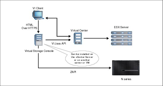
Figure 15-6 VSC possible deployments
|
Tip: To keep it simple, we suggest installing the VSC on the vCenter server.
|
Complete the following steps to install the VSC 4.1:
1. Download the installation program to the Windows server.
2. Run the installation wizard and select the features you would like to install as shown in Figure 15-7.
3. Follow the on-screen instructions.
During the installation process, a prompt displays to select the features of the VSC 4.1 () to be enabled in the environment. The core VSC must be selected. The Provisioning and Cloning and Backup and Recovery features are the former RCU and the SMVI interfaces. Certain subfeatures might require licensing, as described previously. See Figure 15-7.

Figure 15-7 Select VSC features
4. Register the VSC as a plug-in, in the vCenter Server in the window that opens when the process is complete.
The installation process launches the vCenter registration process as shown in Figure 15-8.
Figure 15-8 vCenter registration process
5. Finally, register the VSC plug-in with a vCenter server (Figure 15-9). This final step requires a user with vCenter administrator credentials to complete the registration process.
Figure 15-9 VSC registration with vCenter server
15.2.2 Registration completion
Upon successful registration, the system confirms by issuing the following message on the web page: The registration process has completed successfully!
15.3 Adding storage controllers to the VSC
Adding the storage controllers that host the virtual infrastructure to the VSC is fairly simple:
1. Connect to vCenter by using the vSphere client.
2. Double-click the IBM N series tab on the home panel.
3. Select the Virtual Storage Console tab on the left.
After these steps are completed, the VSC launches and automatically identifies all storage controllers powered by Data ONTAP with the storage connected to the ESXi host in the environment. As an alternative to running discovery for the entire environment, you can select an ESXi host or cluster in the vSphere client and then select the IBM N series tab in the left panel. The VSC then begins discovery of all storage controllers with storage connected to the host or cluster that was selected.
The windows pops-up, as displayed in Figure 15-10, allowing you to enter the user or service account assigned for VSC management on the storage controller. This account can be the root account or one created specifically for the VSC core feature, as described previously.

Figure 15-10 Adding storage controller access in VSC
15.4 Optimal storage settings for ESXi host
The VSC enables the automated configuration of storage-related settings for all ESXi 5.x hosts connected to N series storage controllers. VMware administrators can right-click individual or multiple ESXi host and set the preferred values for these hosts. This functionality sets values for HBAs and CNAs, sets appropriate paths and path selection plug-ins, and provides appropriate settings for software-based I/O (NFS and iSCSI).
To perform the setting, go to the VSC pane, right-click the designated ESXi server, and run the settings as shown in Figure 15-11.
Figure 15-11 Optimize ESX settings
After rebooting the ESX server, we can verify the improved settings. All status indicators are green (see Figure 15-12).

Figure 15-12 Optimized ESX adapter settings
15.5 SnapMirror integration
SnapMirror relationships cannot be configured through VSC. However, VSC can update an existing SnapMirror relationship on the volume underlying the datastore or virtual machine. Preferably, test the SnapMirror relationship from the storage system command line before updating through VSC. This method aids in identifying where any potential issues might occur. If the SnapMirror update is successful from the CLI, but fails from within VSC, the administrator has a better understanding of where to concentrate troubleshooting efforts.
Also, identify the destination storage within VSC in the same manner that the relationship is configured on the storage system. For example, if a SnapMirror relationship is configured on the storage system using IP addresses rather than a DNS name, identify the auxiliary storage to VSC by the IP address and vice versa.
Because its support is for SnapMirror volume only, map one volume per datastore.
During backup creation, SnapManager provides the option of updating an existing SnapMirror relationship. That way, every time a Snapshot is created, the data is transferred to a remote storage system. Whenever the backup of a virtual machine or datastore is initiated with the SnapMirror option, the update starts as soon as the backup completes, after of the current SnapMirror schedule.
For example, by configuring regular SnapMirror updates on a filter after the VSC schedule, you can cut down the time required to update the mirror, because it is done in the interim. However, keep in mind that the updates must be scheduled in such a way that they do not conflict with the SnapManager backup.
15.5.1 SnapMirror destinations
A single SnapMirror destination is supported per volume. If a SnapMirror update is selected as part of a backup on a volume with multiple destinations, the backup fails.
If multiple SnapMirror destinations are required, use a tiered approach when configuring the SnapMirror relationships. For example, if the data must be transferred to four destinations, configure one destination from the primary storage system supported to one destination. Then configure three additional destinations from the auxiliary storage through the storage system CLI.
15.5.2 SnapMirror and deduplication
Preferably, do not use deduplication with Sync SnapMirror. Although technically it works, the integration and scheduling of deduplication with Sync SnapMirror are complicated to implement in the type of rigorous real-world scenarios that demand synchronous replication.
When configuring volume SnapMirror and deduplication, consider the deduplication schedule and the volume SnapMirror schedule. Start volume SnapMirror transfers of a deduplicated volume after deduplication completes (that is, not during the deduplication process). This technique avoids sending undeduplicated data and additional temporary metadata files over the network. If the temporary metadata files in the source volume are locked in Snapshot copies, they also consume extra space in the source and destination volumes. Volume SnapMirror performance degradation can increase with deduplicated volumes.
The scenario described previously has a direct impact on backups configured within VSC when the SnapMirror update option was selected. Avoid scheduling a backup with the SnapMirror update option until a a confirmation of the volume deduplication completeness. Although a few hours must be scheduled to ensure avoiding this issue, the actual scheduling configuration is data and customer dependent.
15.6 VSC in an N series MetroCluster environment
N series MetroCluster configurations consist of a pair of active-active storage controllers. They are configured with mirrored aggregates and extended distance capabilities to create a high-availability solution. This type of configuration has the following benefits:
•Higher availability with geographic protection
•Minimal risk of lost data, easier management and recovery, and reduced system downtime
•Quicker recovery when a disaster occurs
•Minimal disruption to users and client applications
A MetroCluster (either Stretch or Fabric) behaves in most ways similar to an active-active configuration. All of the protection provided by core N series technology (RAID-DP, Snapshot copies, automatic controller failover) also exists in a MetroCluster configuration. However, MetroCluster adds complete synchronous mirroring along with the ability to perform a complete site failover from a storage perspective with a single command.
The following N series MetroCluster types exist and work seamlessly with the complete VMware vSphere and ESX server portfolio:
•Stretch MetroCluster (sometimes called a nonswitched cluster) is an active-active configuration that can extend up to 500 m depending on speed and cable type. It includes synchronous mirroring (SyncMirror) and the ability to do a site failover with a single command.
•Fabric MetroCluster (also called a switched cluster) uses four Fibre Channel switches in a dual-fabric configuration. It uses a separate cluster interconnect card to achieve an even greater distance (up to 100 km depending on speed and cable type) between primary and secondary locations.
The integration of the MetroCluster and VMware vSphere is seamless and provides storage and application redundancy. In addition to connecting to the vSphere environment using FCP, iSCSI, or NFS, this solution can serve other network clients with CIFS, HTTP, and FTP at the same time.
The solution shown in Figure 15-13 provides a redundant VMware server, redundant N series heads, and redundant storage.

Figure 15-13 MetroCluster and VMware vSphere integrated solution
For more information about N series MetroCluster, see the “MetroCluster” chapter in the Redbooks publication, IBM System Storage N series Software Guide, SG24-7129.
15.7 Backup and recovery
This section provides examples of backing up a single virtual machine or the entire DataCenter. The Backup and Recovery capability of the Virtual Storage Console provides rapid backup and recovery of multi-host configurations running on N series storage systems.
You can use this capability to do the following tasks:
•Perform on-demand backups of individual virtual machines, datastores, or a datacenter
•Schedule automated backups of individual virtual machines, datastores, or a datacenter
•Support virtual machines and datastores that are located on either NFS directories or VMFS file systems
•Mount a backup to verify its content prior to restoration
•Restore datastores or virtual machines to the original location
•Restore virtual machine disks (VMDKs) to the original or an alternate location
•Restore one or more files to a guest VMDK without having to restore the entire virtual machine or VMDK using single file restore feature
To configure your storage systems, click the N series icon in the vCenter Server and click Setup under Backup and Recovery in the navigation pane. The Setup panel displays. Click Add on the left side and register your N series system as shown in Figure 15-14.
|
Important: You must register your N series system two times; first, for the VSC and second, for backup and recovery.
|
Figure 15-14 N series registration for backup and restore
15.7.1 Data layout
Layout is indicated by N series best practices for vSphere environments. Move any transient and temporary data, such as the guest operating system swap file, temp files, and page files, to a separate virtual disk on another datastore. The reason is that snapshots of this data type can consume a large amount of storage in a short time because of the high rate of change.
When a backup is created for a virtual machine with VSC, VSC is aware of all VMDKs associated with the virtual machine. VSC initiates a Snapshot copy on all datastores upon which the VMDKs reside. For example, a virtual machine running Windows as the guest operating system has its C drive on datastore ds1, data on datastore ds2, and transient data on datastore td1. In this case, VSC creates a Snapshot copy against all three datastores at underlying volume level. It defeats the purpose of separating temporary and transient data.
Considerations for transient and temporary data
To exclude the datastore that contains the transient and temporary data from the VSC backup, configure the VMDKs residing in the datastore as “Independent Persistent” disks within the VMware Virtual Center (vCenter). After the transient and temporary data VMDKs are configured, they are excluded from both the VMware Virtual Center snapshot and the N series Snapshot copy initiated by VSC.
You must also create a datastore dedicated to transient and temporary data for all virtual machines with no other data types or virtual disks residing on it. This datastore avoids having a Snapshot copy taken against the underlying volume as part of the backup of another virtual machine. Do not deduplicate the data on this datastore.
SnapManager 2.0 for Virtual Infrastructure can include independent disks and exclude datastores from backup.
Including independent disks and excluding datastores
You can avoid having a Snapshot copy performed on the underlying volume as part of the backup of another virtual machine. In this case, preferably, create a datastore that is dedicated to transient and temporary data for all virtual machines. Exclude datastores that contain transient and temporary data from the backup. By excluding those datastores, snapshot space is not wasted on transient data with a high rate of change. In VSC 4.1, when selected entities in the backup span multiple datastores, one or more of the spanning datastores might be excluded from the backup.
After configuration, the transient and temporary data .vmdk are excluded from both the VMware vCenter Snapshot and the N series Snapshot copy initiated by VSC. In VSC 1.0, datastores with only independent disks were excluded from the backup. In VSC 4.1, an option is available to include them in the backup. Datastores with a mix of independent disks and normal disks or configuration files for a VM are included in the backup irrespective of this option.
If you have a normal disk and an independent disk for backup on the same datastore, it is always included for backup irrespective of the “include datastore with independent disk” option. Designate a separate datastore exclusively for swap data.
|
Restore from backup: If you exclude non-independent disks from the backup of a VM, that VM cannot be completely restored. You can perform only virtual disk restore and single file restore from such a backup.
|
15.7.2 Backup and recovery requirements
Your datastore and virtual machines must meet the following requirements before you can use the Backup and Recovery capability:
•In NFS environments, a FlexClone license is required to mount a datastore, restore guest files, and restore a VMDK to an alternate location.
•Snapshot protection is enabled in the volumes where those datastore and virtual machine images reside.
•SnapRestore is licensed for the storage systems where those datastore and virtual machine images reside.
15.7.3 Single wizard for creating backup jobs
With the wizard, you can create manual and scheduled backup jobs. In the right pane, you click Backup, name your new backup job, and select the per-backup job options:
•Initiate SnapMirror update.
•Perform VMware consistency snapshot.
•Include datastores with independent disks.
Virtual Machine backup
To back up individual VMs, follow these steps:
1. Right-click the VM Backup and drill down until you reach the selection to run or schedule a backup, as shown in Figure 15-15.

Figure 15-15 Adding a backup
2. Go to the Welcome panel, and then click Next.
3. Set a Name and Description, specify possible SnapMirror update, or include independent disks (see Figure 15-16), then click Next.

Figure 15-16 Backup options
4. In the following window, you can select scripts to be included in the backup job (see Figure 15-17).
Figure 15-17 Backup scripts
Figure 15-18 Backup schedule
Figure 15-19 Backup job credentials
7. Revise the information entered and click Finish on the Schedule a Backup Wizard and click Next.
8. Select to run your new backup job immediately if you want, as shown in Figure 15-20.
Figure 15-20 Revise scheduled backup job
Datacenter backup
Alternatively, you can also select to back up the whole datacenter as shown in Figure 15-21. Some options are then added to the previously described process.

Figure 15-21 Datacenter backup
The backup wizard adds the option to select the whole datacenter of backup individual datastores as displayed in Figure 15-22.
Figure 15-22 Datacenter backup options
Datastore backup
Alternatively, you can also select to back up an individual datastore as shown in Figure 15-23. Some options are then added to the previously described process.

Figure 15-23 Datastore backup
The backup wizard adds the option to select the whole datastore of backup individual datastores as displayed in Figure 15-24.

Figure 15-24 Datastore backup options
15.7.4 Granular restore options
The following granular restore options are available:
•Restore datastores or virtual machines to the original location.
•Restore virtual machine disks (VMDKs) to the original or an alternate location.
•Restore one or more files to a guest VMDK without having to restore the entire virtual machine or VMDK using single file restore feature.
You can access these options by the tabs as shown in Figure 15-25. Right-click the object that you want to restore.
Figure 15-25 Restore options
You can also select whether you want to restore the entire virtual machine or individual virtual disks, as shown in Figure 15-26. Furthermore, you can select the original or a new location.
Figure 15-26 VSC enhanced restore options
15.7.5 Other features
In addition, VSC offers these features:
•Consistent backup naming
•Serialization of VMware vSphere snapshots
•AutoSupport (ASUP) logging
•vFiler unit support for multiple IP addresses
•Advanced Find option to find specific backups
15.8 Provisioning and cloning
This section provide information and examples of the Provisioning and Cloning functions integrated in VSC.
15.8.1 Features and functions
The provisioning features require at least Data ONTAP 7.3.3 to accomplish the following tasks:
•Creation, resizing, and deletion of VMFS/NFS datastores
•Ability to provision, clone, and resize volumes on secure vFiler units
•Adding storage system using a domain account
•Automation of pathing for both LUNs and NFS datastores
•Running deduplication operations
•Monitoring storage savings and performance
•Protection against failover of NFS mounts to non-redundant VMkernel ports by limiting multiple TCP sessions to iSCSI only
The cloning features allow you to perform the following tasks:
•Creation of multiple virtual machine clones in new or existing datastores (using FlexClone technology)
•Application of guest customization specifications and powering up of new virtual machines
•Redeployment of virtual machines from a baseline image
•Importing virtual machines into virtual desktop infrastructure connection brokers and management tools
•Clone misalignment alert and prevention:
– VM misalignment detection and user notification
– Support for VMFS- and NFS-based VMs
•Ability to import virtual machine settings from a file:
– Non-contiguous virtual machine names
– Guest customization specifications
– Computer name as virtual machine name
– Power-on settings
•Support for these products:
– VMware View 4.0, 4.5, 4.6 & 5.0 or later
– Citrix XenDesktop 4.0 and 5.0 or later
Further features are included:
•Space reclamation management
•Addition of new datastores to new ESX Servers within a cluster
•Service catalog-based provisioning API with enhanced SOAP API to support creation, deletion, and resizing of NFS/VMFS datastores by Storage Services in Provisioning Manager
•Space Reclamation Management
•Mounting of existing datastores when new ESX hosts are added to a cluster or datacenter with support for both NFS and VMFS datastores
•Capability for the user to mount any existing datastore to newly added ESX hosts:
– VDI One-click Golden Template distribution
– This feature allows the user to copy a datastore from a source vCenter to one or more target vCenters
•VMware Virtual Desktop Infrastructure (VDI) enhancements:
– XenDesktop/View import from API
– VDI One-click Golden Template distribution
– Saving of View credentials
– Soap API support for importing newly created clones into Citrix XenDesktop and VMware View
– Storing of View Server credentials
– Elimination of the need to add VMware View Server credentials each time by the cloning wizard
– Creation of multiple View Server pools
15.8.2 Provision datastores
With the Provisioning and Cloning feature of the VSC 4.1, you can create new datastores at the datacenter, cluster, or host level. The new datastore displays on every host in the datacenter or the cluster.
This process launches the N series Datastore Provisioning wizard, which allows you to select the following features:
•Storage controller
•Type of datastore (VMFS or NFS)
•Datastore details, including storage protocol and block size
(if deploying a VMFS datastore)
(if deploying a VMFS datastore)
•Specifying whether the LUN should be thin-provisioned
The provisioning process connects the datastore to all nodes within the selected group.
For iSCSI, FC, and FCoE datastores, the VSC handles storage access control as follows:
For iSCSI, FC, and FCoE datastores, the VSC handles storage access control as follows:
•Creating initiator groups
•Enabling ALUA
•Applying LUN masking
•Applying path selection policies
•Formatting the LUN with VMFS
For NFS datastores, the VSC handles storage access control by managing access rights in the exports file, and it balances the load across all available interfaces.
|
Tip: Remember, if you plan to enable data deduplication, then thin-provisioned LUNs are required to return storage to the free pool on the storage controller.
|
Follow these steps:
1. In the vSphere Client Inventory, right-click a datacenter, cluster, or host and select N series → Provisioning and Cloning → Provision datastore (see Figure 15-27).

Figure 15-27 Provision a datastore
2. Next specify the N series system to use (see Figure 15-28).

Figure 15-28 Select storage controller for provisioning
3. In the following window, select the protocol to use. Here we only have NFS available, as shown in Figure 15-29.
Figure 15-29 Specify datastore type
4. Now specify the new datastore details (see Figure 15-30).

Figure 15-30 New datastore details
5. Before applying your selection, verify the information as shown in Figure 15-31.

Figure 15-31 Review new datastore settings
The new datastore named newDatastore was created on the N series. It can now be mounted to the host you want. Figure 15-32 shows System Manager access and the NFS exports.

Figure 15-32 Verify NFS exports
15.8.3 Managing deduplication
Deduplication eliminates redundant objects on a selected datastore and only references the original object. Figure 15-33 shows how VSC is able to manage deduplication for each individual datastore.
Figure 15-33 Managing deduplication
Possible options to use N series advanced deduplication features are displayed in Figure 15-34. Click OK to apply your settings.

Figure 15-34 Manage deduplication features
15.8.4 Cloning virtual machines
The Provisioning and Cloning capability can theoretically create thousands of virtual machine clones and hundreds of datastores at one time. In practice, however, multiple executions of fewer requests are preferred. The exact size of these requests depends on the size of the vSphere deployment and the hardware configuration of the vSphere Client managing the ESX hosts.
Follow these steps:
1. In the vSphere Client Inventory, right-click a powered-down virtual machine (Figure 15-35) or template and select N series → Provisioning and Cloning → Create rapid clones.
Figure 15-35 Select VM for cloning
2. Next select the controller you want to use for cloning (see Figure 15-36).

Figure 15-36 Select controller for cloning
3. In the following window, select the destination N series system (see Figure 15-37).

Figure 15-37 Select clone target
4. Now specify the VM format for the clone as shown in Figure 15-38.

Figure 15-38 Clone VM format
5. In the following window, specify details for the new datastores as displayed in Figure 15-39.
Figure 15-39 Clone VM details
6. When a summary is provided, click Apply to execute your selection.
After successful completion of the cloning tasks, the new VMs are configured and ready for further use. Figure 15-40 shows the cloning results.
Figure 15-40 Clone results
15.8.5 Reclaiming space on virtual machines
You can use the Reclaim space feature to find free clusters on NTFS partitions and make them available to the operating system.
Before you begin
The Reclaim space feature allows Data ONTAP to use space freed when data is deleted in guest operating systems.
This feature has the following requirements:
•VMDKs attached to the virtual machine must be on NFS-backed datastores.
|
Tip: The Reclaim space feature is not supported if the NFS datastore is backed by a qtree on a vFiler unit.
|
•VMDKs must have NTFS partitions.
|
Tip: If the VMDK is unpartitioned or FAT, the Provisioning and Cloning capability incorrectly lists the disk as having an NTFS partition after the task completes and displays a “Yes” in the “Has NTFS partition(s)?” column. Even though the VMDK now appears to be partitioned, it is still unpartitioned or FAT, and you cannot reclaim space on it.
|
•ISOs mounted to the virtual machine must be contained in an NFS datastore.
•Storage systems must be running Data ONTAP 7.3.4 or later.
•You should have the VMware guest tools installed.
•When the Reclaim space feature is running, you must not power on the virtual machine.
•You cannot use the cloning feature when the target virtual machine is being used by either the Backup and Recovery capability or the Optimization and Migration capability.
Steps
Follow these steps:
1. Right-click a datastore or virtual machine and select IBM N series → Provisioning and Cloning → Reclaim space (Figure 15-41).

Figure 15-41 VM reclaim space
2. Click OK.
If the virtual machine is powered on, the Reclaim space feature powers it off. After the process completes, the Reclaim space feature returns the virtual machine to its previous state.
|
Tip: If you are using this feature when the virtual machine is powered on, make sure you have the guest operating system tools installed. Without these tools, the Reclaim space feature does not work when it has to power down the virtual machine.
|
If you do not want to install these tools, then you should power down the virtual machine before running the Reclaim space feature.
15.9 Optimum VM availability
The Monitoring and Host Configuration capability includes tools for detecting and correcting misaligned disk partitions and for setting virtual machine timeouts as shown in Figure 15-42.

Figure 15-42 VSC tools
|
Tip: The Optimization and Migration capability of VSC allows you to perform online alignments on VMFS-based datastores without having to take your VM down. This capability also lets you review the alignment status of VMs and migrate groups of VMs.
|
15.9.1 Optimizing VM SCSI BUS
One of the components of the VSC is the GOS timeout scripts. These scripts are a collection of ISO images that can be mounted by a VM to configure its local SCSI to values that are optimal for running in a virtual infrastructure.
Installing GOS scripts
The ISO images of the guest operating system (GOS) scripts are loaded on the VSC for VMware vSphere server. Mount and run them from the vSphere Client to set the storage timeouts for virtual machines.
Before you begin
The virtual machine must be running.
The CD-ROM must already exist in the virtual machine or it must be added.
The script must be installed from the copy of the VSC for VMware vSphere registered to the vCenter Server that manages the VM.
Steps
1. Open the vSphere Client and log into your vCenter Server.
2. Select a Datacenter in the Inventory panel, and then select the IBM N series tab.
3. In the Monitoring and Host Configuration capability, select the Tools panel.
4. Under Guest OS Tools, right-click the link to the ISO image for your guest operating system version and select Copy to clipboard.
5. In the vSphere Client, select the desired VM and click the CD/DVD Connections icon.
6. Select CD/DVD Drive 1 > Connect to ISO image on local disk.
7. Paste the link you copied into the File Name field and then click Open.
If you receive an authorization error, be sure you select the IBM N series tab and click Yes to proceed if a security certificate warning is displayed.
Also, be sure that the link you are using is from the copy of the VSC for VMware vSphere running on the vCenter Server that manages the VM.
After you finish
Log on to the VM and run the script to set the storage timeout values
15.9.2 Optimal storage performance
VMs store their data on virtual disks. Similar to physical disks, these virtual disks contain storage partitions and file systems, which are created by the guest operating system of the VM. To provide optimal disk I/O within the VM, you must align the partitions of the virtual disks to the block boundaries of VMFS and the block boundaries of the storage array. Failure to align all three of these items results in a dramatic increase of I/O load on a storage array and negatively affects the performance of all VMs being served on the array.
IBM, VMware, other storage vendors, and VMware partners recommend aligning the partitions of VMs and the partitions of VMFS datastores to the blocks of the underlying storage array.
Datastore alignment
N series systems automate the alignment of VMFS with iSCSI, FC, and FCoE LUNs. This task is automated during the LUN provisioning phase of creating a datastore when you select the LUN type “VMware” for the LUN. Customers deploying VMware over NFS do not need to align the datastore. With any type of datastore, VMFS or NFS, the virtual disks contained within should have the partitions aligned to the blocks of the storage array.
VM partition alignment
When aligning the partitions of virtual disks for use with N series systems, the starting partition offset must be divisible by 4,096. For example, the starting partition offset for Microsoft Windows 2000, 2003, and XP operating systems is 32,256. This value does not align to a block size of 4,096.
Virtual machines running a clean installation of Microsoft Windows 2008, Windows 7, or Windows Vista operating systems automatically have their starting partitions set to 1,048,576. By default, this value does not require any adjustments.
|
Tip: If your Windows 2008 or Windows Vista VMs were created by upgrading an earlier version of Microsoft Windows to one of these versions, then it is highly probable that these images require partition alignment.
|
15.9.3 VM partition alignment
Storage alignment is critical, so aligning the file system within the VMs to the storage array is very important. This process should not be considered optional. Misalignment at a high level results in decreased usage.
Issues with partition alignment
Failure to align the file systems results in a significant increase in storage array I/O to meet the I/O requirements of the hosted VMs. Customers might notice this impact when:
•Running high-performance applications
•Achieving less than impressive storage savings with deduplication
•Perceiving a need to upgrade storage array hardware
The reason for these types of issues is misalignment results in every I/O operation executed within the VM to require multiple I/O operations on the storage array.
Simply put, you can save your company a significant amount of capital expenditures by optimizing the I/O of your VMs.
Identifying partition alignment
To verify the starting partition offset for a VM based on Windows, complete the following steps:
1. Log in to the VM.
2. Run the system information utility (or msinfo32) to find the starting partition offset setting.
3. To run msinfo32, click Start > All Programs > Accessories > System Tools > System Information (Figure 15-43 on page 271).

Figure 15-43 System information
15.9.4 N series MBR Tools: Identification of partition alignment status
IBM N series systems provides a tool, MBRScan, that runs on an ESX host and can identify if partitions are aligned with Windows and Linux VMs running within VMFS and NFS datastores. MBRScan runs against the virtual disk files that compose a VM. Although this process only requires a few seconds per VM to identify and report on the status of the partition alignment, each VM must be powered off. For this reason, it might be easier to identify the file system alignment from within each VM, because this action is nondisruptive.
MBRScan is an integrated component of the VSC.
Corrective actions for VMs with misaligned partitions
After you identify that your VMs have misaligned partitions, we recommend correcting the partitions in your templates as the first corrective action. This step makes sure that any newly created VM is properly aligned and does not add to the I/O load on the storage array.
Correcting partition misalignment with N series MBR Tools
As part of the VSC tools, IBM N series systems provides a tool, MBRAlign, that runs on an ESX host and can correct misaligned primary and secondary master boot record-based partitions for guest operating systems. When using MBRAlign, the VM that is undergoing the corrective action must be powered off.
MBRAlign provides flexible repair options. For example, it can be used to migrate and align a virtual disk as well as change the format from a thin to thick vmdk. We highly recommend creating a Snapshot copy before executing MBRAlign. This Snapshot copy can be safely discarded after a VM has been corrected, powered on, and the results have been verified.
You must download these tools before you can use them. There is a set of tools for ESX hosts and one for ESXi hosts. You must download the correct tool set for your hosts. MBRAlign can be obtained from the Tools Download link in the VSC.
Enabling the ESXi secure shell
When you are using ESXi, it is a good practice to enable the Secure Shell (SSH) protocol before you download the MBR tools. That way you can use the scp command if you need to copy the files.
Before you begin
ESXi does not enable this shell by default.
Steps
1. From an ESXi host, press the key combination ALT F2 to access the Direct Console User Interface (DCUI) panel.
2. Press the F2 function key to get to the Customize System panel.
3. Go to Troubleshooting Options.
4. Press Enter at the Enable SSH prompt.
5. Press Enter at the Modify ESX Shell timeout prompt.
6. Disable the timeout by setting the value to zero (0) and pressing Enter.
7. Go to Restart Management Agents and press Enter.
8. Press F11.
Downloading and installing MBR tools for ESXi hosts
If you have an ESXi host, you must download and install the version of the MBR (master boot record) tools for ESXi. The MBR tools enable you to detect and correct misaligned disk partitions for guest operating systems. These tools must be installed and run directly on the ESXi host. Before you install them, you must extract them from the .tar file into the root directory on the ESXi host.
Before you begin
You must be able to open a console connection to the ESXi host.
|
Tip: The MBR tools can only be used when the virtual machine (VM) is powered off. If you want to perform online alignments on VMFS-based datastores without having to take your VM down, you can use the Optimization and Migration capability. In that case, you do not need to download the MBR tools.
|
Steps
Follow these steps:
1. Open the vSphere Client and log into your vCenter Server.
2. Select a Datacenter in the Inventory panel, and then select the IBM N series tab.
3. In the Monitoring and Host Configuration capability, select the Tools panel.
4. Under MBR Tools, click the Download (For ESXi 4.x and ESXi 5.x) button.
Make sure you download the MBR Tools for ESXi. If you download the wrong MBR tools file, the tools will not work.
5. When the File Download dialog is displayed, click Save.
6. (ESXi 4.x) If you are using ESXi 4.x, manually enable the ESXi shell and SSH so that you can use the scp command to copy the files to the correct directories if needed.
ESXi 4.x does not enable the ESXi shell and SSH by default. You can enable these options from the physical host or from the vCenter. The following steps enable these options from the vCenter.
|
Tip: vCenter creates a configuration alert for each ESXi host that has the options enabled.
|
To enable the ESXi shell, perform the following steps:
•From vCenter, highlight the appropriate ESXi host.
•Go to the Configuration Tab.
•In the left pane under Software, select Security Profile.
•Select Properties from the Services pane.
•Highlight the ESXi Shell service and select Options.
•Select Start and Stop with Host.
•Click Start.
To enable the ESXi SSH, perform the following steps:
•From vCenter, highlight the appropriate ESXi host.
•Go to the Configuration Tab.
•In the left pane under Software, select Security Profile.
•Select Properties from the Services pane.
•Highlight the SSH service and select Options.
•Select Start and Stop with Host.
•Click Start.
7. Copy the MBR tools for ESXi file to the root (/) directory of the ESXi host. If you are using ESXi 4.x, use the Troubleshooting Console. If you are using ESXi 5.x, use the Technical Service Console.
You might need to open ESXi firewall ports to enable copying the tools to the host.
|
Tip: The MBR tools libraries must be located in specific directories on the host. Be sure to download the file to the root directory of the ESXi host.
|
8. Extract the files by entering the following command:
tar -zxf mbrtools_esxi.tgz
If you did not download the file to the root directory, you must manually move the files to that directory.
|
Tip: ESXi does not support -P with the tar command.
|
After you finish
Run the mbralign tool to check and fix the partition alignment.
Linux VMs that boot using the GRUB boot loader require the following steps after MBRAlign has been run.
1. Connect a Linux CD or CDROM ISO image to the Linux VM.
2. Boot the VM.
3. Select to boot from the CD.
4. Execute GRUB setup to repair the boot loader, when appropriate.
Creating properly aligned partitions for new VMs
Virtual disks can be formatted with the correct offset at the time of creation by simply booting the VM before installing an operating system and manually setting the partition offset. For Windows guest operating systems, consider using the Windows Preinstall Environment boot CD or the alternative “live DVD” tools. To set up the starting offset, complete the following steps (Figure 15-44).
Figure 15-44 Running diskpart to set a proper starting partition offset
1. Boot the VM with the Microsoft WinPE CD.
2. Select Start, select Run, and enter diskpart
3. Enter select disk 0
4. Enter create partition primary align=32
5. Reboot the VM with the WinPE CD.
6. Install the operating system as normal.
You can also create properly aligned VMDKs with fdisk from an ESX console session.
15.9.5 Windows VM file system performance
If your VM is not acting as a file server, consider implementing the following change to your VMs, which disables the access time updates process in the Microsoft Windows NT File System (NTFS). This change reduces the amount of IOPS occurring within the file system.
Reducing IOPS in the file system
To make the proposed change, complete the following steps:
1. Log into a Windows VM.
2. Click Start → Run, and enter CMD.
3. Enter:
fsutil behavior set disablelastaccess 1
Disk defragmentation utilities
VMs stored on N series storage arrays should not use disk defragmentation utilities because the WAFL file system is designed to optimally place and access data at a level below the guest operating system (GOS) file system.
15.10 VSC commands
You can use the Virtual Storage Console command-line interface to perform specific Backup and Recovery capability tasks.
All VSC commands can be performed by using either the GUI or the CLI, with some exceptions. For example, only the creation of scheduled jobs and their associated retention policies and single file restore can be performed through the GUI.
Remember the following general information about the commands:
•VSC commands are case-sensitive.
•There are no privilege levels; any user with a valid user name and password can run all commands.
You can launch the Virtual Storage Console CLI by using the desktop shortcut
or the Windows Start menu. Double-click the VSC CLI desktop icon or navigate to
Start → All Programs → IBM → Virtual Storage Console →IBM N series VSC CLI.
or the Windows Start menu. Double-click the VSC CLI desktop icon or navigate to
Start → All Programs → IBM → Virtual Storage Console →IBM N series VSC CLI.
15.11 Scripting
VSC provides users the ability to run pre, post, and failure backup phase scripts as stated in the previous section. These scripts are any executable process on the operating system in which the VSC is running. When defining the backup to run, the pre, post, and failure backup scripts can be chosen by using either the VSC GUI or CLI. The scripts must be saved in the <VSC Installation>smviserverscripts directory. Each chosen script runs as a pre, post, and failure backup script.
From the GUI, you can select multiple scripts by using the backup creation wizard or when editing an existing backup job as shown in Figure 15-17 on page 253. The UI lists all files found in the <VSC Installation>smviserverscripts directory. VSC runs the scripts before creating the VMware snapshots and after the cleanup of VMware snapshots.
When VSC starts each script, a progress message is logged indicating the start of the script. When the script completes, or is terminated by SAN volume controller because it was running too long, a progress message is logged. It indicates the completion of the script and states if the script was successful or failed. If a script is defined for a backup but is not found in the scripts directory, a message is logged stating that the script cannot be found.
The VSC maintains a global configuration value to indicate the amount of time that a script can execute. After a script runs for this length of time, the script is terminated by the VSC to prevent run-away processing by scripts. If VSC must terminate a script, it is implicitly recognized as a failed script and might force termination of the VSC backup in the pre-backup phase.
With the default settings, VSC waits for up to 30 minutes for each script to complete in each phase. This default setting can be configured by using the following entry in the <VSC Installation>smviserveretcsmvi.override file:
smvi.script.timeout.seconds=1800
VSC backup scripts receive input from the environment variables. This way, the input can be sent in a manner that avoids CLI line length limits. The set of variables varies based on the backup phase.
..................Content has been hidden....................
You can't read the all page of ebook, please click here login for view all page.