

High availability and disaster recovery
This chapter provides information about the opportunities for high availability (HA) when using VMware vSphere 5.1 and N series storage in the same environment. It then explains the implementation of disaster recovery using the functions of these technologies. It includes the following topics:
12.1 High availability
This section provides details about some of the high availability features of the N series and Virtual Infrastructure 3 solution.
12.1.1 N series node failures
In a normal configuration, two N series servers are clustered. If a failure occurs in one of the nodes, the second system automatically takes on the load of both servers without any manual intervention required.
However, if a failure affects both nodes, such as a power failure for the whole server environment, a disaster recovery implementation is required. This implementation can be in the form of a second pair of N series servers in a location nearby, using MetroCluster. Or it can be done with a pair of N series servers in a more remote location, using SnapMirror.
An N series cluster (standard N series configuration) offers the following high availability features:
•Built-in redundancy for a failure of a power supply, fan, or disk controller
•RAID-DP for a single or dual disk failure
•Multipath for a single disk path or port failure
•Snapshot copies for accidental erasure or destruction of data
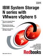
MetroCluster is an extended N series cluster for distances of up to 100 km with fiber connectivity between sites. It provides the following additional HA features:
•SyncMirror for a triple disk failure or complete disk shelf failure
•Redundancy for a host bus adapter (HBA) or port failure
•Active-active controller configuration for a storage controller failure
•MetroCluster for a data center power or environmental outage
•The ability of VMware HA cluster to be split across the MetroCluster
Figure 12-1 shows a fabric attached MetroCluster configuration.
Figure 12-1 MetroCluster configurations
12.1.2 VMware host failures
With two or more VMware hosts configured in a cluster with a shared storage, you can have high availability features. Virtual machines on a failed host can be quickly restarted on another host, as long as there is capacity available on the remaining hosts. This feature is enabled by VMware High Availability (HA). As a preferred practice, provide enough capacity on your environment for the failure of at least one host, also known as N+1. Depending on your availability requirements and the speed of growth of your environment, you might even want to size it N+2.
Another feature available is Dynamic Resource Scheduler (DRS), which manages the load of the guests across the servers in the cluster. If one of the hosts becomes overloaded, guests can be automatically moved to a server with a less load without any downtime. If you plan to use the VMware HA feature, you can also use the DRS feature. This feature allows virtual machines to be evenly balanced across the cluster in the event of a host failure.
If you do not have high availability on your environment, use operating system or application-level clustering. If your application is not state-aware, use load balancers, as for web servers.
12.2 Disaster recovery options
You can mirror an N series node (cluster) at the primary site to an N series node at a secondary site (Figure 12-2). It can be used in a development or test capacity during normal operation if the loss of it in a disaster is acceptable. Otherwise, it can be used for on demand or out-of-band additional capacity.
Disaster recovery can also be done using a FlexClone of the SnapMirror. You can even start the virtual machines in the DR site while the run on the primary site if their network is isolated. This method uses a lot less disk than traditional methods, because cloning does not require a full copy of the source, but rather only as changes occur on either copy.
A VMware host or cluster must be in the disaster recover site also to run the VMs present on the cloned storage at DR site. However, it does not have to be the same hardware, thus providing more flexibility to your planning.

Figure 12-2 N series Gateway cluster configuration
12.3 Setting up disaster recovery
In this section, you configure a Virtual Infrastructure 3 and N series environment to use the N series SnapMirror feature. This feature provides replication of the datastores to a second location that is ready for use in the event of a disaster.
The following tasks are involved:
1. Configuring the source location storage
2. Enabling SnapMirror on the N series storage systems
3. Configuring the mirror
4. Starting the mirror
The SnapMirror configuration is similar in many ways to SnapVault configuration.
12.3.1 Setting up the primary storage
If you are setting up a new environment, you can plan your storage based on your disaster recovery requirements. Where possible, co-locate data with similar disaster recovery requirements on the same volumes. More importantly, try not to store data with separate requirements on the same volume. For example, make sure that your transient data is stored on separate volumes from your vital data.
To set up the primary storage, follow these steps:
1. Set up your primary storage as for any N series storage for VMware.
2. On the destination storage system, create a volume for each volume you intend to replicate that is at least as large as the source volume. However, do not create LUNs, because they are replicated from the source.
3. Restrict access to the destination volumes by entering the vol restrict <vol_name> command (Example 12-1). This command prevents the volume from being accessed by the virtual machines outside of a disaster situation.
Example 12-1 Restricting a destination volume
N6070A> vol restrict vol_vm_dr
Volume 'vol_vm_dr' is now restricted.
N6070A>
4. On the destination storage system, create a volume with the appropriate LUNs that are the same as each of the volumes on the source that contains the transient data.
5. Disable the automatic snapshots of both the source and destination volumes unless you have a separate need for them.
|
SnapMirror: Unlike SnapVault, which requires qtrees, SnapMirror works at either the qtree level or volume level. The examples in this section use volumes, but you can use qtrees instead if you prefer.
|
12.3.2 Licensing SnapMirror
To use SnapMirror, you must apply your site license to the source and destination N series storage systems and to the clustered nodes for each system, if applicable:
1. In N series System Manager, in the left navigation pane, select Configuration → System Tools → Licenses.
Figure 12-3 SnapMirror License installed
When installed, the SnapMirror options become available in the left navigation pane (Figure 12-4).

Figure 12-4 SnapMirror menu options
12.3.3 Setting permissions
Set the permissions to allow the destination system to access SnapMirror on the source by entering the following command on the source system (Example 12-2):
options snapmirror.access host=<secondary>
Example 12-2 Setting the SnapVault permissions
N6070A> options snapmirror.access host=9.155.66.103
N6070A> options snapmirror.access
snapmirror.access host=9.155.66.103
N6070A>
The options snapmirror.access command verifies that the permission was assigned correctly.
You can also use this function in System Manager. In the left navigation pane, select SnapMirror → Remote Access → Add. However, use the CLI command shown in Example 12-2 to confirm that the access was assigned correctly.
12.3.4 Configuring the volume mirror
To configure the volume mirror, follow these steps:
1. Set up the mirror transfer from the secondary system. In System Manager, in the left navigation pane (Figure 12-5), select SnapMirror → in the right pane, select Create.

Figure 12-5 Selecting the option to add SnapMirror
Figure 12-6 SnapMirror welcome panel
3. In the next panel, you need to select the current host as Source or Destination as shown in Figure 12-7. In this example, the N series N6070A will be used as source. Select Source then click Next.

Figure 12-7 SnapMirror system selection
4. In the Source Selection panel, select the Volume name or qtree path to be mirrored. (Figure 12-8). You can type the path or navigate using browse. Then click Next.

Figure 12-8 Browse source path
5. In the next panel, select the Destination System where the volume will the mirrored (Figure 12-9). Then click Next.
Figure 12-9 Select destination system
6. In the next panel, select the destination path for the mirrored volume. You can create a new volume or select an existing. The volume must be in restricted mode in the second case. We are going to create a new volume (Figure 12-10). Then click Next.

Figure 12-10 Select the destination path
7. In the Schedule and Initialize panel, you can create a schedule for the SnapMirror relationship or just leave On demand. We are going to create a basic schedule. Select the Create new schedule for SnapMirror relationship option and click Create (Figure 12-11).

Figure 12-11 Create SnapMirror schedule
8. Still in the Schedule and Initialize panel (Figure 12-12), after you configure the mirror, you must initialize it to start the initial mirror copy to the destination storage system. Select the Initialize SnapMirror relationship check box and click Next.

Figure 12-12 Initialize SnapMirror
9. In the next wizard panel (Figure 12-13), you can select how much bandwidth you want reserve for the SnapMirror. Leave it unlimited unless you experience any network performance issues after the creation. Click Next.

Figure 12-13 Select bandwidth
10. The next panel is the SnapMirror Relationship summary. Review and click Next.
11. Verify the SnapMirror status by selecting SnapMirror in the System Manager left pane as shown in Figure 12-14.
Figure 12-14 SnapMirror status
12.4 Recovering from a disaster
If a disaster (or possibly a full test of the disaster recovery capability) occurs, perform the following tasks:
1. Break the mirror to make the mirrored data writable.
2. Map the LUNs.
3. Rescan the VMware hosts to see the LUNs.
4. Reinventory the virtual machines.
5. Start the virtual machines.
12.4.1 Breaking the mirror
During the setup procedure, the mirror volumes in the destination location were restricted to prevent writes. To remove this restriction and allow the data to be mounted and accessed, break the mirror:
1. Run System Manager on the destination N series system.
2. In the left navigation pane of System Manager (Figure 12-15), select SnapMirror → Highlight the desired SnapMirror relationship → Operations → Break.
Figure 12-15 Break SnapMirror
3. In the SnapMirror Break confirmation panel (Figure 12-16), select OK to break the selected SnapMirror relationship and click Break.
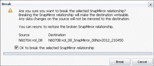
Figure 12-16 Confirm SnapMirror break
4. In the SnapMirror pane (Figure 12-17), you can see that the mirror was broken.
Figure 12-17 Broken SnapMirror
5. Repeat these steps for each mirrored volume that you require access to on the destination system.
12.4.2 Mapping the LUNs and rescanning VMware hosts
Now that the mirror is broken and the data is available, any LUNs on the volume must be mapped so that the VMware host can use them.
1. Map the LUN as already previously explained.
2. Create a datastore using the LUN you just mapped.
3. Then reinventory the virtual machines.
12.4.3 Starting virtual machines
Now that the virtual machines are configured correctly, start them:
1. Right-click a virtual machine and select Power, then Power On.
2. Verify the task list to confirm that the guest started correctly.
3. Repeat these steps for each guest you want to start in the DR environment. You might also want to start the remote console for the guests, or run application diagnostic tests for each application, to confirm that everything is working as expected.
12.5 Returning to production
In a case where a disaster occurred and the environment is failed over to the disaster recovery site, the data stored in there is the most current. If the production environment comes back online later, the data and server load might need to be transferred back. Similar to regular SnapMirror transfers, the production site can be updated from the disaster recovery data while the disaster recovery site is operational.
This update might be large if the production data was lost or corrupted, or it might be small if the production data was unaffected by the disaster. The server load change requires an outage. Therefore, it is better to schedule this outage to occur in non-productions hours.
Returning to production entails the following high-level procedure:
1. Repair or recover the production N series storage system to its original state, with the correct software, options, and so on.
2. Copy the data (or changes) back to the production site from the disaster recovery site while the disaster recovery system is operational for users.
3. Prevent users or systems from accessing the disaster recovery data, and copy any final updates to production.
4. Split the mirror between the two sites.
5. Remap the production LUNs.
6. Rescan the VMware hosts, and inventory the virtual machines.
7. Start the virtual machines.
8. Re-establish SnapMirror from production to the disaster recovery site.
Because many of these steps are the same as in the disaster scenario, only the new steps are explained in detail in this section.
|
GUI versus CLI commands: It is possible to perform some of the steps in this section and the following sections from System Manager. However, some are not available as they are not commonly performed operations. As a result, they are all shown as CLI commands.
|
12.5.1 Replicating data from disaster recovery to the production site
After the production site N series server becomes available, copy the data from the disaster recovery N series system to the production system. You can do this task by using one of the procedures in the following sections, depending on the state of the production N series data.
Before you begin, assign permissions in the reverse direction enter the following command:
options snapmirror.access host=<secondary>
Production N series data still intact
If the data in the production site was not lost, you need only to copy updates back from the disaster recovery site. You can perform this task by entering the following command:
snapmirror resync -S <DR_syste,m>:<volume> <prod_system>:<volume>
Figure 12-18 shows how to perform the same operation using the System Manager console.
Figure 12-18 Resync SnapMirror
Production N series recovery
If the data in the production site was lost or corrupted during the disaster situation, you must re-create the volumes and then copy back all of the data from the disaster recovery site. You re-create the volume in the production site, and restrict the volume. Initialize the production system from the good copy on the disaster recovery system by entering the following command on the production N series system:
snapmirror initialize -S <dr_system>:<dr_vol> <prod_system>:<prod_vol>
Example 12-3 shows the snapmirror initialize command.
Example 12-3 Copying the disaster recovery environment data to the production site
N6070A> snapmirror initialize -S 9.155.66.103:vol_08_SnapMirror_08Nov2012_210450 N6070A:vol_08
Transfer started.
Monitor progress with 'snapmirror status' or the snapmirror log.
After the initialization is complete, the production system has a copy of the data again.
12.5.2 Preventing access and performing a final update
To ensure that the data is up to date, all virtual machines running on the disaster recovery site N series system must be shut down. Shutting down this system ensures that the final updates of data can be transferred back to the production system.
If a time lag exists between when the initialization was started and when it is convenient to schedule an outage on the guests, perform an update while the virtual machines are still running. Then shut down all guests that are accessing the disaster recovery site data.
When there is no longer anything accessing the DR site data, run the following command from the production N series system to perform the update:
snapmirror update -S <dr_system>:<dr_vol> <prod_system>:<prod_vol>
Example 12-4 shows the results of the snapmirror update command.
Example 12-4 Updating data between the disaster recovery and production sites
N6070A> snapmirror update -S 9.155.66.103:vol_08_SnapMirror_08Nov2012_210450 N6070A:vol_08
Transfer started.
Monitor progress with 'snapmirror status' or the snapmirror log.
N6070A>
12.5.3 Splitting the mirror
Now both the disaster recovery and production systems have the same data, and no changes are occurring on either system. Therefore, the mirror can be broken.
From the production N series system, quiesce and break the mirror by using the following command:
snapmirror break <volume_name>
Example 12-5 Breaking the mirror
N6070A> snapmirror break vol_08
snapmirror break: Destination vol_08 is now writable.
Volume size is being retained for potential snapmirror resync. If you would like to grow the volume and do not expect to resync, set vol option fs_size_fixed to off.
N6070A>
12.5.4 Re-establishing the mirror from the production to disaster recovery site
Finally, you can perform a resynchronization to make the disaster recovery site a mirror of the production site again. Enter the following command on the disaster recovery N series system:
snapmirror resync <vol_name>
Example 12-6 shows the results of the snapmirror resync command.
Example 12-6 Resync from the production to disaster recovery site
N6070A> snapmirror resync vol_08_SnapMirror_08Nov2012_210450
The resync base Snapshot will be: N6070B(0151697146)_vol_08_SnapMirror_08Nov2012_210450.2
Are you sure you want to resync the volume? yes
Thu Nov 9 16:32:15 CET [snapmirror.dst.resync.info:notice]: SnapMirror resync of vol_08_SnapMirror_08Nov2012_210450 to 9.155.66.103:vol_08_SnapMirror_08Nov2012_210450 is using
N6070B(0151697146)_vol_08_SnapMirror_08Nov2012_210450.2 as the base Snapshot.
Volume vol_08_SnapMirror_08Nov2012_210450 will be briefly unavailable before coming back online.
Thu Nov 9 16:32:16 CET [wafl.snaprestore.revert:notice]: Reverting volume vol_08_SnapMirror_08Nov2012_210450 to a previous Snapshot.
Thu Nov 9 16:32:16 CET [wafl.vol.guarantee.replica:info]: Space for replica volume 'vol_08_SnapMirror_08Nov2012_210450' is not guaranteed.
Revert to resync base Snapshot was successful.
Thu Nov 9 16:32:16 CET [snapmirror.dst.resync.success:notice]: SnapMirror resync of vol_08_SnapMirror_08Nov2012_210450 to 9.155.66.103:vol_08_SnapMirror_08Nov2012_210450 successful.
Transfer started.
Monitor progress with 'snapmirror status' or the snapmirror log.
N6070A>
12.5.5 Configuring VMware hosts and virtual machines on the production site
Now the production N series system is the source again, and replication is occurring back to the disaster recovery site. Perform the following steps to start the guests on the production VMware hosts:
1. Rescan the VMware hosts to view the datastores again.
The new datastore might be displayed as a snapshot. Therefore, you can rename it to the original name before using it, as shown in Figure 12-19.

Figure 12-19 Recovered datastore
2. Reinventory the virtual machines.
You might need to delete the original virtual machines first.
3. Reconfigure the virtual machines for the transient data volumes of the production site.
4. Start the virtual machines.
12.6 Disaster recovery testing
In a disaster recovery test, it is often desirable to perform testing without disrupting either the source environment or the destination copy of the data. Such a test is relatively easy to perform with the use of N series cloning, so that the disaster recovery environment can be tested against a clone of the mirrored data. Similar to other N series cloning processes, the clone requires little additional disk capacity in the disaster recovery site, because only changes are written to disk.
To perform this type of test, the LAN environment for the disaster recovery VMware hosts must be separated from the production environment. Thus, the guests can be started without causing conflicts in the network. You can complete this task by isolating the VMware hosts from the network (while still providing connectivity to the N series server). Alternatively, if feasible, you can set up isolated virtual networks within the VMware hosts. This second option, however, prevents communication between guests on separate hosts.
You can perform a disaster recovery test with N series cloning by using the following high-level procedure:
1. Verify that SnapMirror Snapshots in the disaster recovery location are current.
2. Clone the Snapshot volumes.
3. Bring the cloned LUNs online, and map them for access by the VMware hosts.
4. Rescan the VMware hosts.
5. Add the virtual machines to the inventory.
6. Start the virtual machines.
7. Perform disaster recovery application testing.
8. When complete, stop the virtual machines, remove them from the inventory, and destroy the cloned volumes.
..................Content has been hidden....................
You can't read the all page of ebook, please click here login for view all page.