

Host and storage connectivity
This chapter describes the test environment setup that is used in this book. It also discusses options for host to storage connectivity, which includes host-cluster configuration, protocols such as Fibre Channel and Internet Small Computer System Interface (iSCSI), iSCSI Extensions for RDMA (iSER), and multipath configuration options.
This chapter includes the following sections:
2.1 Test environment implementation
Figure 2-1 depicts the configuration and connectivity for the test environment for host connectivity that is used in this book. An IBM FlashSystem 9100 and an IBM FlashSystem 9200 are cabled to two IBM SAN24B-5 Fibre Channel switches. Each canister on each
IBM FlashSystem has two ports that are connected to each switch. Four VMware hosts are used for this book.
IBM FlashSystem has two ports that are connected to each switch. Four VMware hosts are used for this book.
Each host is connected to each switch:
•The hosts with the blue-colored connections are zoned to the FS9100 with blue-colored connections.
•The hosts with the green-colored connections are zoned to the FS9200 with green-colored connections.

Figure 2-1 Configuration and connectivity for the test environment that is used in this book
2.1.1 IBM FlashSystem host clusters
IBM FlashSystem products support host clusters starting with IBM Spectrum Virtualize 7.7.1. With a host cluster, a user can create a group of hosts to form a cluster. A cluster is treated as a single entity, which allows multiple hosts to have access to the same set of volumes.
Volumes that are mapped to a host cluster are assigned to all members of the host cluster that use the same Small Computer System Interface (SCSI) ID. Before this feature was implemented in IBM Spectrum Virtualize, as an example, an Elastic Sky X (ESX) cluster would be created as a single host object, containing all the worldwide node names (WWNNs) for the hosts in the cluster, up to 32.
With host clusters, a storage administrator can define individual host objects for each Elastic Sky X integrated (ESXi) host and add them to a host cluster object that represents each vSphere cluster. If hosts are later added to the host cluster, they automatically inherit shared host cluster volume mappings. Within the host cluster object, you can have up to 128 hosts in a single host cluster object. Host clusters are easier to manage than single host objects because the 32 worldwide port name (WWPN) limitation is removed.
The minimum size of a cluster is two nodes for vSphere high availability (HA) to protect workloads if one host stops functioning. However, in most use cases, a 3-node cluster is more appropriate because you have the option of running maintenance tasks on an ESXi server without having to disable HA.
Configuring large clusters has benefits too. You typically have a higher consolidation ratio, but there might be a downside if you do not have enterprise-class or correctly sized storage in the infrastructure. If a data store is presented to a 32-node or a 64-node cluster and the virtual machines (VMs) on that data store are spread across the cluster, there is a chance that you will run into SCSI-locking contention issues. Using a VMware vSphere Storage APIs – Array Integration (VAAI) aware array helps reduce this problem with Atomic Test and Set (ATS). However, if possible, consider starting small and gradually growing the cluster size to verify that your storage behavior is not impacted.
Figure 2-2 shows one of the VMware host clusters that was used in the test configuration for this book. There are two hosts that are defined in the VMware host cluster.

Figure 2-2 VMware host clusters that were used in the test configuration
|
Note: Do not add Non-Volatile Memory Express (NVMe) hosts and SCSI hosts to the same host cluster.
|
Figure 2-3 shows the volumes that are assigned to the host cluster.

Figure 2-3 Volumes that are assigned to the host cluster
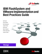
Figure 2-4 shows one of the hosts in the host cluster with the volumes that are connected to it. The volumes were assigned to the host cluster, and not directly to the host. Any hosts that are added to a host cluster have all of the volumes mapped to the host cluster automatically assigned to the hosts.
|
Note: Private mappings can still be provisioned to individual hosts within a host cluster, for example for storage area network (SAN) Boot configurations.
|
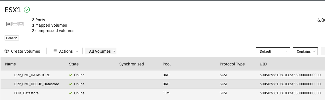
Figure 2-4 One of the hosts in the host cluster with the volumes that are connected to it
2.1.2 Use cases for implementing throttles
With IBM FlashSystem storage you can configure throttles for the following items:
•Hosts
•Host clusters
•Volumes
•SCSI offload
•Storage pools
A common use case for throttles on hosts, host clusters, and volumes can be applied when test and production workloads are mixed on the same IBM FlashSystem. Test-related workloads should not affect production, so you can throttle test hosts and volumes to give priority to production workloads.
IBM Spectrum Virtualize supports commands that are used for SCSI offload and VMware VAAI.
•SCSI offload enables the host to offload some data operations to the storage system.
•VAAI enables VMware hosts to also offload some operations to supported storage systems.
Both technologies reduce traffic on the storage network, and load on the host. Hosts use these offload commands to perform tasks such as formatting new file systems or performing data copy operations without a host needing to read and write data. Examples are the WRITE SAME and XCOPY commands. IBM Spectrum Virtualize 8.1.0.0 introduced support for WRITE SAME when UNMAP is enabled. WRITE SAME is a SCSI command that tells the storage system to write the same pattern to a volume or an area of a volume.
When SCSI UNMAP is enabled on IBM FlashSystem storage, it advertises this situation to hosts. At versions 8.1.0.0 and later, some hosts respond to the UNMAP command by issuing a WRITE SAME command, which can generate large amounts of I/O. If the back-end storage system cannot handle the amount of I/O, volume performance can be impacted. IBM Spectrum Virtualize offload throttling can limit the concurrent I/O that is generated by the WRITE SAME or XCOPY commands.
To enable offload throttling:
1. Run the svcupgradetest utility to obtain the recommended bandwidth throttle value:
a. For systems managing any enterprise or nearline storage, the recommended value is 100 MBps.
b. For systems managing only tier1 flash or tier0 flash, the recommended value is
1000 MBps.
1000 MBps.
2. Enable the offload throttle by using the following command-line interface (CLI) command:
throttle -type offload -bandwidth bandwidth_limit_in_MB
2.1.3 Data reduction pools
Data reduction can increase storage efficiency and reduce storage costs, especially for
IBM FlashSystem storage systems. Data reduction reduces the amount of data that is stored on both the internal drives and the virtualized external storage systems by reclaiming previously used storage resources that are no longer needed by host systems.
IBM FlashSystem storage systems. Data reduction reduces the amount of data that is stored on both the internal drives and the virtualized external storage systems by reclaiming previously used storage resources that are no longer needed by host systems.
IBM FlashSystem storage systems implement data reduction by using data reduction pools (DRPs). A DRP can contain thin-provisioned or compressed volumes. DRPs also provide more capacity to volumes in the pool by supporting data deduplication.
With a log-structured pool implementation, DRPs help to deliver more consistent performance from compressed volumes. DRPs also support compression of all volumes in a system, potentially extending the benefits of compression to all data in a system. Traditional storage pools have a fixed allocation unit of an extent, and that does not change with DRPs. However, features like Thin Provisioning and IBM Real-time Compression (RtC) use smaller allocation units and manage this allocation with their own metadata structures. These features are described as Binary Trees or Log Structured Arrays (LSAs).
For thin-provisioned volumes to stay thin, you need to be able to reclaim capacity that is no longer used, or for LSAs (where all writes go to new capacity), garbage-collect the old overwritten data blocks. This action also needs to be done at the smaller allocation unit size in a DRP volume.
Figure 2-5 shows the types of volumes that can be created in a DRP.
•DRP fully allocated volumes provide the best performance for the IBM FlashSystem products, but storage efficiency and space savings are not realized.
•Thin-compressed volumes provide storage-space efficiency with the best performance of the four options for space-efficient volumes.

Figure 2-5 Types of volumes that can be created in a data reduction pool
For more information about data reduction pools, see Implementation Guide for IBM Spectrum Virtualize Version 8.5, SG24-8520.
2.2 Host connectivity protocols
IBM FlashSystem support both Ethernet-based and Fibre-Channel-based host-attachment protocols:
•Ethernet-based protocols include iSCSI and iSER. Both of these protocols can be implemented over existing Ethernet networks and do not require a dedicated storage network.
•Fibre-Channel-based protocols include Non-Volatile Memory Express over Fibre Channel (FC-NVMe) and traditional SCSI Fibre Channel, which is most often referred to as Fibre Channel.
2.2.1 iSCSI
iSCSI connectivity is a software feature that is provided by the SAN Volume Controller (SVC) code. The iSCSI protocol is a block-level protocol that encapsulates SCSI commands into Transmission Control Protocol/Internet Protocol (TCP/IP) packets. Therefore, iSCSI uses an IP network rather than requiring the Fibre Channel (FC) infrastructure. The iSCSI standard is defined by Request for Comment (RFC) 3720.
An iSCSI client, which is known as an iSCSI initiator, sends SCSI commands over an IP network to an iSCSI target. A single iSCSI initiator or iSCSI target is called an iSCSI node.
You can use the following types of iSCSI initiators in host systems:
•Software initiator: Available for most operating systems (OSs), including IBM AIX, Linux, and Windows.
•Hardware initiator: Implemented as a network adapter with an integrated iSCSI processing unit, which is also known as an iSCSI host bus adapter (HBA).
Ensure that the iSCSI initiators and targets that you plan to use are supported. Use the following sites for reference:
iSCSI qualified name
An IBM FlashSystem cluster can provide up to eight iSCSI targets, one per canister. Each canister has its own iSCSI Qualified Name (IQN), which, by default, is in the following format:
iqn.1986-03.com.ibm:2145.<clustername>.<nodename>
An alias string can also be associated with an iSCSI node. The alias enables an organization to associate a string with the iSCSI name. However, the alias string is not a substitute for the iSCSI name.
|
Important: The cluster name and node name form part of the IQN. Changing any of them might require reconfiguration of all iSCSI nodes that communicate with IBM FlashSystem.
|
2.2.2 iSER
IBM FlashSystem that run IBM Spectrum Virtualize v8.2.1 or greater support iSER for host attachment, which is implemented by using RDMA over Converged Ethernet (RoCE) or Internet Wide-Area RDMA Protocol (iWARP). This feature supports a fully Ethernet-based infrastructure (and not Fibre Channel) in your data center:
•IBM FlashSystem internode communication with 2 or more IBM FlashSystem in a cluster.
•HyperSwap.
Using iSER requires that an Ethernet adapter is installed in each node, and that dedicated Remote Direct Memory Access (RDMA) ports are used for internode communication. RDMA enables the Ethernet adapter to transfer data directly between nodes. The direct transfer of data bypasses the central processing unit (CPU) and cache and makes transfers faster.
Requirements for RDMA connections:
•25 Gbps Ethernet adapter is installed on each node.
•Ethernet cables between each node are connected correctly.
•Protocols on the source and destination adapters are the same.
•Local and remote IP addresses can be reached.
•Each IP address is unique.
•The local and remote port virtual LAN identifiers are the same.
•A minimum of two dedicated ports are required for node-to-node RDMA communications to ensure the best performance and reliability. These ports cannot be used for host attachment, external storage, or IP replication traffic.
•A maximum of four ports per node are allowed for node-to-node RDMA connections.
2.2.3 FC-NVMe
The NVMe transport protocol provides enhanced performance on high-demand
IBM FlashSystem drives. NVMe is a logical device interface specification for accessing non-volatile storage media. Host hardware and software use NVMe to fully leverage the levels of parallelism possible in modern solid-state drives (SSDs).
IBM FlashSystem drives. NVMe is a logical device interface specification for accessing non-volatile storage media. Host hardware and software use NVMe to fully leverage the levels of parallelism possible in modern solid-state drives (SSDs).
Compared to the SCSI protocol, NVMe improves I/O and brings performance improvements such as multiple, long command queues, and reduced latency. SCSI has one queue for commands, unless multi-queue support such as blk_mq is enabled on the operating system, and you are limited to the number of cores in the CPUs on the host.
NVMe is designed to have up to 64 thousand queues. In turn, each of those queues can have up to 64 thousand commands that are processed simultaneously. This queue depth is much larger than SCSI typically has. NVMe also streamlines the list of commands to only the basic commands that Flash technologies need.
IBM FlashSystem implements NVMe by using the FC-NVMe protocol. FC-NVMe uses the Fibre Channel protocol as the transport so that data can be transferred from host memory to the target, which is similar to RDMA. For more information about NVMe, see IBM Storage and the NVM Express Revolution, REDP-5437.
Every physical FC port on IBM FlashSystem storage supports four virtual ports: one for SCSI host connectivity, one for FC-NVMe host connectivity, one for SCSI host failover, and one for FC-NVMe host failover. Every NVMe virtual port supports the functions of NVMe discovery controllers and NVMe I/O controllers. Hosts create associations (NVMe logins) to the discovery controllers to discover volumes or to I/O controllers to complete I/O operations on NVMe volumes. Up to 128 discovery associations are allowed per node, and up to 128 I/O associations are allowed per node. An extra 128 discovery associations and 128 I/O associations per node are allowed during N_Port ID virtualization (NPIV) failover.
At the time of this writing, IBM Spectrum Virtualize 8.5 supports a maximum of 64 NVMe hosts. For more information, see IBM Support.
If FC-NVMe is enabled on the IBM FlashSystem, each physical WWPN reports up to four virtual WWPNs. Table 2-1 lists the NPIV ports and port usage when FC-NVMe is enabled.
Table 2-1 NPIV ports and port usage when FC-NVMe is enabled
|
NPIV port
|
Port description
|
|
Primary Port
|
The WWPN that communicates with back-end storage if the IBM FlashSystem is virtualizing any external storage.
|
|
SCSI Host Attach Port
|
The virtual WWPN that is used for SCSI attachment to hosts. This WWPN is a target port only.
|
|
Failover SCSI Host Port
|
The standby WWPN that is brought online only if the partner node in an I/O group goes offline. This WWPN is the same WWPN as the primary host WWPN of the partner node.
|
|
NVMe Host Attach Port
|
The WWPN that communicates with hosts for FC-NVMe. This WWPN is a target port only.
|
|
Failover NVMe Host Attach Port
|
The standby WWPN that is brought online only if the partner node in an I/O group goes offline. This WWPN is the same WWPN as the primary host WWPN of the partner node.
|
For more information about FC-NVMe and configuring hosts to connect to IBM FlashSystem storage systems by using FC-NVMe, see VMware ESXi installation and configuration for NVMe over Fibre Channel hosts
Figure 2-6 shows how to add a FC-NVMe host to an IBM FlashSystem from the Add Host window.
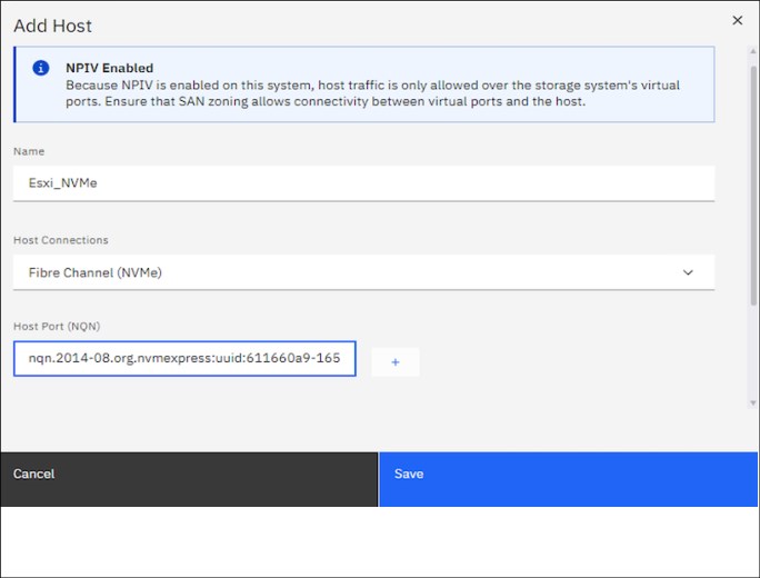
Figure 2-6 Adding an FC-NVMe host to IBM FlashSystem
After adding a VMware FC-NVMe host to an IBM FlashSystem, you must discover the storage subsystem on the VMware ESXi host. You must discover both nodes for each adapter on the IBM FlashSystem by using the NVMe WWPNs that are zoned with the ESXi host. To do so, click DISCOVER CONTROLLERS in the window that is shown in Figure 2-7.

Figure 2-7 Discovering the IBM FlashSystem NVMe controller on VMware
The window that is shown in Figure 2-8 opens and shows the available SCSI and NVMe devices and data stores.

Figure 2-8 SCSI and NVMe devices and data stores
NVMe devices are managed by the VMware high-performance plug-in (HPP). To see the NVMe devices, run the esxcli storage hpp device list command on esxcli.
2.2.4 SCSI Fibre Channel
FC is a storage networking transport that transports SCSI commands and data from hosts to storage. The Fibre Channel protocol (FCP) is the transport layer that transmits the SCSI commands. Hosts and storage systems are connected to switches to create a SAN. Figure 2-1 on page 8 is an example of two single-switch SANs that are used to create this book.
The IBM Spectrum Virtualize software that runs on IBM FlashSystem storage uses the SCSI protocol to communicate with its clients, and presents storage space in form of SCSI logical units (LUs) identified by SCSI logical unit numbers (LUNs).
|
Note: In formal practice, LUs and LUNs are different entities. In practice, the term LUN is often used to refer to a logical disk or LU.
|
Since most applications do not directly access storage, but work with files or records, the OS of a host must convert these abstractions to the language of storage, which are vectors of storage blocks that are identified by logical block addresses within an LU. In IBM Spectrum Virtualize, each of the externally visible LUs is internally represented by a volume, which is an amount of storage that is taken out of a storage pool. Hosts use the SCSI protocol to send I/O commands to IBM FlashSystem storage to read and write data to these LUNs.
As with FC-NVMe host attachment, if NPIV is enabled on the IBM FlashSystem storage system, hosts attach to a virtual WWPN. Table 2-1 on page 14 lists the SCSI and Failover Host Attach Ports.
2.2.5 NVMe over Remote Direct Memory Access
IBM Spectrum Virtualize 8.5.0 can be attached to an NVMe host through NVMe over Remote Direct Memory Access (NVMe over RDMA). NVMe over RDMA uses RoCE v2 as the transport protocol. RoCE v2 is based on UDP. RDMA is a host-offload and host-bypass technology that allows an application (including storage) to make data transfers directly to and from another application’s memory space. The RDMA-capable Ethernet network interface cards (RNICs), and not the host, manage reliable data transfers between source and destination.
VMware V7.0u2 and later supports RoCE v2 as host connectivity for IBM Spectrum Virtualize 8.5 storage systems.
RNICs can use RDMA over Ethernet through RoCE encapsulation. RoCE wraps standard InfiniBand payloads with Ethernet or IP over Ethernet frames, which is sometimes called InfiniBand over Ethernet. There are two main RoCE encapsulation types:
•RoCE v1
Uses dedicated Ethernet Protocol Encapsulation to send Ethernet packets between source and destination MAC addresses by using Ethertype 0x8915.
•RoCE v2
Uses dedicated UDP over Ethernet Protocol Encapsulation to send IP UDP packets by using port 4791 between source and destination IP addresses. UDP packets are sent over Ethernet by using source and destination MAC addresses.
RoCE v2 is not compatible with other Ethernet options, such as RoCE v1.
|
Note: Unlike RoCE v1, RoCE v2 is routable.
|
For more information about configuring the VMware ESXi for NVMe over RDMA on
IBM FlashSystem storage systems, see Configuring the VMware ESXi operating system for NVMe over RDMA host.
IBM FlashSystem storage systems, see Configuring the VMware ESXi operating system for NVMe over RDMA host.
2.3 Multi-path considerations
This section describes multi-path considerations, such as path selection policies and zoning considerations.
2.3.1 Native multipathing path-selection policies
There are three general VMware native multipathing (NMP) plug-in path-selection policies or path-selection plug-ins (PSPs). A PSP is a VMware ESXi host setting that defines a path policy to an LUN. The three PSPs are Most Recently Used (MRU), Fixed, and Round-Robin (RR).
Most Recently Used
The policy selects the first working path, discovered at system start time. If this path becomes unavailable, the ESXi or ESX host switches to an alternative path and continues to use the new path while it is available. This policy is the default for LUNs that are presented from an Active/Passive array. ESXi and ESX host switches do not return to the previous path if it returns, and the host switch remains on the working path until the working path fails.
|
Tip: The VMware preferred flag can be set on a path. This flag is not applicable if the path selection policy is set to Most Recently Used.
|
Fixed
The Fixed policy uses the designated preferred path flag if it is configured. Otherwise, it uses the first working path that is discovered at system start time. If the ESXi host cannot use the preferred path or it becomes unavailable, the ESXi host selects an alternative available path. The host automatically returns to the previously defined preferred path when it becomes available. This policy is the default for LUNs that are presented from an active/active storage array.
Round-Robin
The Round-Robin policy is the recommended policy for IBM FlashSystem products. This path selection policy uses a round-robin algorithm to load balance paths across all LUNs when connecting to a storage array. This policy is the default for VMware starting with ESXi 5.5. You must explicitly set Round-Robin for versions earlier than ESXi 5.5.
Data can travel through only one path at a time:
•For active/passive storage arrays, only the paths to the preferred storage array are used.
•For an active/active storage array, all paths are used for transferring data, assuming that paths to the preferred yes are available.
With Asymmetric Logical Unit Access (ALUA) in an active/active storage array, such as the IBM FlashSystem 9200 and 9500 systems, only the optimized paths to the preferred control enclosure node are used for transferring data. Round-Robin cycles through only those optimized paths. You should configure pathing so that half the LUNs are preferred by one control enclosure node, and the other half are preferred by the other control enclosure node.
Latency Round-Robin is activated by default when Round-Robin is selected as the path selection policy. Latency Round-Robin considers I/O bandwidth and path latency when selecting an optimal path for I/O. When this latency mechanism is used, Round-Robin dynamically selects the best path for better load-balancing. For more information about Latency Round-Robin, see Change Default Parameters for Latency Round-Robin.
Round-Robin path selection limit
Round-Robin Path switching supports two limits:
•Input/output operations per second (IOPS) limit: A new path is used after a specified number of IOPS are completed on the current path.
•Bytes limit: A new path is used after a specified number of bytes are transferred on the current path.
The default path selection limit is IOPS, and the default value is 1000 IOPS before the path changes. In some cases, a host can experience latency to storage with no latency seen on the SAN. In these cases, the load of 1000 IOPS saturates the bandwidth of the path. Lowering this value can increase storage performance and help prevent this cause of latency. The recommended path-selection limit setting for IBM FlashSystem is to use IOPS and set the value to 1. For more information about the IOPS limit, see Adjusting Round Robin IOPS limit from default 1000 to 1 (2069356).
Path selection with claim rules
Claim rules help to set the path selection limit and path selection policy settings in new LUNs that are assigned to ESXi host. Example 2-1 shows an example of creating a claim rule.
Example 2-1 Creating a claim rule for an IBM Spectrum Virtualize system to set the path selection limit to 1
esxcli storage nmp satp rule add -s VMW_SATP_ALUA -V IBM -M "2145" -c tpgs_on --psp="VMW_PSP_RR" -e "IBM arrays with ALUA support" -O "iops=1"
To configure the claim rule, use vSphere Host Profile window, as shown in Figure 2-9.
Figure 2-9 Configuring a claim rule by using the Host Profile window
|
Note: Existing and previously presented devices must be manually set to Round-Robin with an IOPS limit of 1. Optionally, the ESXi host can be restarted so that it can inherit the multipathing configuration that is set by the new rule.
|
2.3.2 High-performance plug-in and path selection policies
Since VMware 6.7, there is a new multipath plug-in that is called HPP. The HPP replaces the NMP for high-speed devices, such as NVMe. The HPP is the default plug-in that claims NVMe over Fabrics (NVMe-oF) targets. Within ESXi, the NVMe-oF targets are emulated and presented to users as SCSI targets. The HPP supports only active/active and implicit ALUA targets.
In vSphere 7.0 Update 1 and earlier, NMP remains the default plug-in for local NVMe devices, but you can replace it with HPP. Starting with vSphere 7.0 Update 2, HPP becomes the default plug-in for local NVMe and SCSI devices, but you can replace it with NMP.
Consider the following configuration recommendations for HPP:
•Use the vSphere version that supports HPP.
•Use HPP for local NVMe and SCSI devices, and NVMe-oF devices.
•If you use NVMe-oF, do not mix transport types to access the same namespace.
•Configure your VMs to use VMware Paravirtual controllers.
•Set the latency sensitive threshold to bypass the I/O scheduler.
•If a single VM drives a significant share of the device's I/O workload, consider spreading the I/O across multiple virtual disks. Attach the disks to separate virtual controllers in the VM.
By default, ESXi passes every I/O through the I/O scheduler. However, using the scheduler might create internal queuing, which is not efficient with the high-speed storage devices.
You can configure the latency sensitive threshold and enable the direct submission mechanism that helps I/O to bypass the scheduler. With this mechanism enabled, the I/O passes directly from Pluggable Storage Architecture (PSA) through the HPP to the device driver.
For the direct submission to work properly, the observed average I/O latency must be lower than the latency threshold that you specify. If the I/O latency exceeds the latency threshold, the system stops the direct submission, and temporarily reverts to using the I/O scheduler. The direct submission is resumed when the average I/O latency drops below the latency threshold again.
|
Note: HPP does not benefit when the systems perform lower than 200,000 IOPS.
|
Example 2-2 shows how to list the devices that are controlled by the HPP.
Example 2-2 Output of using the esxcli storage hpp device list command
[root@localhost:~] esxcli storage hpp device list
eui.70000000000004b5005076081280000c
Device Display Name: NVMe Fibre Channel Disk (eui.70000000000004b5005076081280000c)
Path Selection Scheme: LB-RR
Path Selection Scheme Config: {iops=1,bytes=10485760;}
Current Path: vmhba64:C0:T0:L3
Working Path Set: vmhba64:C0:T0:L3, vmhba65:C0:T0:L3
Is SSD: true
Is Local: false
Paths: vmhba64:C0:T0:L3, vmhba65:C0:T1:L3, vmhba65:C0:T0:L3, vmhba64:C0:T1:L3
Use ANO: false
To support multipathing, HPP uses the Path Selection Schemes (PSSs) when selecting physical paths for I/O requests.
ESXi supports the following path selection mechanisms for HPP.
Load Balance - Round-Robin
Load Balance - Round-Robin (LB-RR) is the default scheme for the devices that are claimed by HPP. After transferring a specified number of bytes or I/Os on a current path, the scheme selects the path by using the Round-Robin algorithm.
Load Balance - Latency
To achieve better load-balancing results, Load Balance - Latency (LB-Latency) dynamically selects an optimal path by considering the following path characteristics:
•The latency evaluation time parameter indicates at what time interval, in milliseconds, that the latency of paths must be evaluated.
•The sampling I/Os per path parameter controls how many sample I/Os must be issued on each path to calculate the latency of the path.
Load Balance - IOPS
When using Load Balance - IOPS (LB-IOPS), after transferring a specified number of I/Os on a current path (the default is 1000), the system selects an optimal path that has the least number of outstanding I/Os.
Load Balance - Bytes
When using Load Balance - Bytes (LB-BYTES), after transferring a specified number of bytes on a current path (the default is 10 MB), the system selects an optimal path that has the least number of outstanding bytes.
Fixed
With this scheme, a designated preferred path is used for I/O requests. If the preferred path is not assigned, the host selects the first working path that is discovered at start time. If the preferred path becomes unavailable, the host selects an alternative available path. The host returns to the previously defined preferred path when it becomes available again.
When you configure FIXED as a path selection mechanism, select the preferred path.
2.4 Zoning considerations
Modern SAN switches have three types of zoning available:
•Port zoning
•Worldwide node name (WWNN) zoning
•WWPN zoning
The preferred method is to use only WWPN zoning. You should not mix zoning types. WWPN-based zoning is more flexible than Switchport-based and is required if the IBM Spectrum Virtualize NPIV feature is enabled. Switch-port based zoning can cause failover of the NPIV ports to not work correctly, and in certain configurations can cause a host to be connected to the IBM FlashSystem on both the physical and virtual WWPNs.
For more information about the NPIV feature and switch-port zoning, see Using Switch Port-Based Zoning with the IBM Spectrum Virtualize NPIV Feature.
A common misconception is that WWPN zoning provides poorer security than port zoning. However, modern SAN switches enforce the zoning configuration directly in the switch hardware. Also, you can use port-binding functions on SAN switches to enforce a WWPN to be connected to a particular SAN switch port, or to prevent unauthorized devices from logging in to your fabric if they are connected to switch ports. Lastly, the default zone on each of your virtual fabrics should have a zone policy of deny, which means that any device in the default zone cannot communicate with any other device on the fabric. All unzoned devices that are not in at least one named zone) are in the default zone.
Naming convention
When you create and maintain a Storage Network zoning configuration, you must have a defined naming convention and zoning scheme. If you do not define a naming convention and zoning scheme, your zoning configuration can be difficult to understand and maintain. Environments have different requirements, which means that the level of detailing in the zoning scheme varies among environments of various sizes. Therefore, ensure that you have an understandable scheme with an appropriate level of detailing for your environment. Then, use it consistently whenever you change the environment.
Aliases
Use zoning aliases when you create your IBM FlashSystem zones. Aliases make your zoning easier to configure and understand and minimize errors. Define aliases for the
IBM FlashSystem physical WWPNs, the SCSI-FC WWPNs, and the FC-NVMe WWPNs if you have that feature enabled.
IBM FlashSystem physical WWPNs, the SCSI-FC WWPNs, and the FC-NVMe WWPNs if you have that feature enabled.
You should have the following zones:
•A zone containing all of the IBM FlashSystem aliases for the IBM FlashSystem physical WWPNs that are dedicated for internode use.
•A zone containing all of the IBM FlashSystem aliases for both the local and remote IBM FlashSystem physical WWPNs that are dedicated for partner use if replication is enabled.
•One zone for each host containing the aliases for the host and either the IBM FlashSystem SCSI-FC virtual WWPNs, or the FC-NVMe virtual WWPNS, depending on which type of host attachment the host is using. For an alternative to this approach, see “Multi-inititiator zoning” on page 23.
•One zone per storage system containing the aliases for the storage system and the
IBM FlashSystem physical WWPNs if the IBM FlashSystem is virtualizing storage.
IBM FlashSystem physical WWPNs if the IBM FlashSystem is virtualizing storage.
|
Tip: If you have enough IBM FlashSystem ports available and you have many hosts that you are connecting to an IBM FlashSystem, you should use a scheme to balance the hosts across the ports on the IBM FlashSystem. You can use a simple round-robin scheme, or you can use another scheme, such as numbering the hosts with the even-numbered hosts zoned to the even-numbered ports and the odd-numbered hosts zoned to the odd-numbered ports. Whichever load-balancing scheme that you choose to use, you should ensure that the maximum number of paths from each host to each volume is four paths. The maximum supported number is eight paths. The recommended number is four paths per volume.
Note: Do not add NVMe and SCSI ports to the same zone.
|
For SAN zoning best practices, see the IBM San Zoning Best Practices at Support page.
Multi-inititiator zoning
For host clusters such as VMware, it is desirable to have all hosts in the cluster in the same zone because it makes administration and troubleshooting easier. This setup can cause issues where a malfunctioning host affects all other hosts in the zone. Traditional best-practice zoning is to have only one initiator (host) per zone.
In recent years, Brocade released the Peer Zoning feature. Cisco released a similar feature that is called Smart Zoning. Both features allow multiple initiators to be in the same zone, but prevent them from connecting to each other. They can connect only to target ports in the zone, which allows multiple hosts to be in the same zone, but prevents the issue of a malfunctioning host port from affecting the other ports.
For VMware clusters, the preferred zoning configuration is to have the ports for all of the hosts in the cluster in a zone with the IBM FlashSystem virtual WWPN.
•Brocade Peer zoning must be enabled for this zone on Brocade fabrics. Brocade Peer Zoning was introduced in FOS v7.4.x.
For more information about Brocade Peer zoning, see Brocade Fabric OS Administration Guide 9.0.x.
•Cisco Smart Zoning must be enabled for this zone on Cisco fabrics. Cisco Smart Zoning was introduced in NX-OS v5.2.x.
For more information about Cisco Smart Zoning, see “Configuring and Managing Zones” in Cisco MDS Family 9000 NX-OS Fabric Configuration Guide.
2.5 Recommendations for tuning ESXi hosts
This section describes tuning ESXi hosts for better storage performance.
Marking the hosts as flash
In some cases, VMware sees volumes as a hard disk drives (HDD) even if they are not serial-attached SCSI (SAS) or near-line SAS (NL-SAS) volumes. Check the current drive type on ESXi and change it to Flash before creating the data store.
Setting the Round-Robin IOPS limit to 1
The recommended option for configuring Round-Robin and the correct IOPS limit is to create a rule that sets any new device that is added to that host automatically as a Round-Robin PSP with an I/O Operation Limit value of 1.
VMware Paravirtual SCSI
Paravirtual SCSI (PVSCSI) adapters are high-performance storage adapters that can result in greater throughput and lower CPU utilization. PVSCSI adapters are best for SAN environments, where hardware or applications drive a high amount of I/O throughput. The VMware PVSCSI adapter driver is also compatible with the Windows Storport storage driver. PVSCSI adapters are not suitable for direct-attached storage environments.
Large-scale workloads with intensive I/O patterns require adapter queue depths greater than the PVSCSI default values. At the time of writing, the PVSCSI queue depth default values are 64 (for device) and 254 (for adapter). You can increase PVSCSI queue depths to 254 (for device) and 1024 (for adapter) inside a Windows or Linux VM.
Eager-zeroed thick virtual disks
An eager-zeroed thick disk has all space allocated and zeroed out at the time of creation, which increases the time that it takes to create the disk, but results in the best performance, even on the first write to each block.
Latency sensitive threshold on NVMe volumes
When you use the HPP for your storage devices, set the latency sensitive threshold for the device so that I/O can avoid the I/O scheduler. By default, ESXi passes every I/O through the I/O scheduler. However, using the scheduler might create internal queuing, which is not efficient with the high-speed storage devices. You can configure the latency sensitive threshold and enable the direct submission mechanism that helps I/O to bypass the scheduler. With this mechanism enabled, the I/O passes directly from PSA through the HPP to the device driver. If the I/O latency exceeds the latency threshold, the system stops the direct submission, and temporarily reverts to using the I/O scheduler. The direct submission is resumed when the average I/O latency drops below the latency threshold.
..................Content has been hidden....................
You can't read the all page of ebook, please click here login for view all page.