
Stack-Based Algorithms for HDR Capture and Reconstruction
O. Gallo*; P. Sen† * NVIDIA Research, Santa Clara, CA, United States
† University of California, Santa Barbara, CA, United States
Abstract
High-dynamic-range (HDR) images can be created with standard camera hardware by the capturing and combining of multiple pictures, each sampling a different segment of the irradiance distribution of a scene. This seemingly straightforward process involves several important steps, which will be the focus of this chapter. We start by examining the problem of selecting the set of exposures that properly measures the full dynamic range of a particular scene, a process known as metering for HDR. We then describe how to perform radiometric calibration, which is needed to estimate the incoming irradiance from the low-dynamic-range images. After that, we offer an overview of the methods to merge multiple low-dynamic-range images into a single HDR image. Finally, we discuss methods to compensate for camera and scene motion, which would otherwise cause artifacts in the final HDR image.
Keywords
Stack-based HDR; Metering; Radiometric calibration; Deghosting; Nonrigid registration
Acknowledgments
P. Sen was partially funded by National Science Foundation grants IIS-1342931 and IIS-1321168. The authors also thank the many researchers within the computational imaging community who published the work described in this chapter. Without their innovations, none of this would have been possible.
3.1 Introduction
In this chapter, we examine approaches to capture high-dynamic-range (HDR) images and video using conventional digital cameras. This is in contrast to approaches with cameras that are specifically designed to capture a larger dynamic range in a single exposure (see Chapter 2). Since standard digital sensors can capture only a small fraction of the incident irradiance (see Chapter 1), approaches for capturing HDR images with a standard sensor must take a stack of N sequential images Z1,…,ZN with different exposure settings and combine their information together as a postprocess to reconstruct an HDR irradiance image, E. We refer to these as stack-based algorithms for HDR capture and reconstruction.
While the focus of this book is HDR video, a thorough discussion of HDR capture for still images is very important. First and foremost, a large portion of the methods proposed for HDR video use a similar strategy, in that they acquire a stream of differently exposed frames. Additionally, many of the topics we cover in this chapter are central also in the case of HDR video, even when the latter is captured with specialized sensors.
From a historical perspective, and although HDR imaging has only recently become widespread, the analog counterpart of today’s stack-based approaches was introduced as early as the mid-1800s by French photographer Gustave Le Gray. To expand the limited dynamic range he could capture on film, he literally cut and pasted together multiple films, each measuring a different portion of the dynamic range. The resulting landscapes are simply breathtaking (see Fig. 3.1). The idea of taking multiple shots to extend the dynamic range a camera can capture reappeared in the context of digital photography over a 100 years later: two decades ago, Mann (1993)1 and Madden (1993) proposed combining multiple low-dynamic-range (LDR) pictures into a single HDR image. Since then, stack-based HDR imaging has attracted growing interest from the research community. Today, most consumer cameras, and even some high-end DSLR cameras, offer HDR shooting modes generally based on this strategy.

The layout of this chapter roughly follows the steps involved in stack-based HDR imaging generation. First, we must determine how many pictures to take and what their exposure times should be to adequately capture the dynamic range of a given scene (Section 3.2). Once the images have been captured, we must merge their information to reconstruct the HDR result (Section 3.3). These approaches work well for static scenes captured with tripod-mounted cameras.
However, if the scene is dynamic or the camera is handheld, the slight differences between exposures in the stack will produce unacceptable ghostlike artifacts in the final result. Since this scenario is very common, a large body of research on stack-based HDR image reconstruction focuses on handling motion (Section 3.4), and two major kinds of methods have been developed: (1) methods that remove ghosting artifacts by rejecting information from images that contain motion (Section 3.4.2), and (2) methods that perform some kind of nonrigid registration to align the input images (Section 3.4.3).
Throughout the chapter, we will use the notation shown in Table 3.1, often rewriting equations from the different articles to match this notation for consistency and clarity.
Table 3.1
Notation Used in This Chapter
| N | number or exposures in the source image stack |
| {Zi}i=1:N | stack of N input LDR source images |
| Zi(p) | value of pixel p in the ith exposure |
| {ti}i=1:N | exposure times for each of the N source images on the stack |
| Ri,j | exposure ratio between exposures j and i (if the exposure time is the only parameter changing, then Ri,j = tj/ti) |
| E | HDR irradiance image of the scene (W/m2), which the algorithms in this chapter attempt to reconstruct from an input stack |
| estimated scene irradiance | |
| {Xi}i=1:N | stack of N exposure images (J/m2, computed as Xi = E ⋅ ti) |
| f(⋅) | camera response function, which converts the pixel exposure X to the pixel value Z — that is, Zi(p) = f(Xi(p)) |
| g(⋅) | inverse camera response function, which converts pixel values to pixel exposures — that is, Xi(p) = g(Zi(p)) (note that g(⋅) is not an exact inverse of f(⋅)) |
| wi(p) | weight matrix indicating how well exposed each LDR pixel is (eg, for merging LDR images to form a final HDR result) |
| Zref | reference input LDR source, for algorithms that need a reference image from the stack to be specified |
3.2 Metering for HDR Imaging
When a photographer presses the shutter button to take a picture, digital cameras analyze the scene content to determine the optimal capture parameters. Collectively, the algorithms designed to select these parameters are referred to as the three A’s: autofocus, auto white balance, and autoexposure. The first two will not be discussed in this chapter as they do not have any specialized counterpart for the process of HDR capture. Autoexposure, also called metering, is the process of selecting the combination of exposure time, ISO setting, and aperture that optimally captures a specific scene on the basis of some criterion. The heuristics involved in metering algorithms range from considerations about motion blur to signal quality in terms of both the signal-to-noise ratio (SNR) and quantization. Additionally, they may include optimizations better suited to work with the algorithms used by the image signal processor in later stages.
In the absence of automatic methods, metering is the photographer’s responsibility, requiring both technical and artistic skills. This process is particularly involved in the context of analog photography, because of the nonlinearity of the film’s response. An example of a beautifully developed theory for metering is the Zone System by Ansel Adams and Fred Archer (Adams, 1948). In a nutshell, Adams and Archer suggest dividing the range of gray levels that can be captured by the camera into ten segments, also called “zones.” Metering then becomes the process of selecting an exposure time that assigns zones to the correct range of irradiance in the scene. For instance, the exposure time should be selected so that the fifth zone captures the values in the middle of the scene’s irradiance distribution.
However, for the capture of the scene with a single exposure and a digital camera, an optimal autoexposure algorithm is expose to the right (ETTR)2 ; in essence, ETTR selects the longest possible exposure time that does not induce saturation (or blur for handheld cameras or dynamic scenes). The resulting image minimizes the impact of photon shot noise. Because of the discrete nature of light, the actual number of photons hitting a pixel in a given time can be modeled by a random Poisson process. Noting that for large numbers a Poisson process can be approximated by a Gaussian process, we have that the number of incoming photons is ![]() , where μ is the average number of photons collected. Therefore, the SNR increases with a longer exposure time, as the latter increases the average number of photons collected:
, where μ is the average number of photons collected. Therefore, the SNR increases with a longer exposure time, as the latter increases the average number of photons collected: ![]() . A shorter exposure time also causes a larger quantization error: the analog signal from the sensor is linearly quantized by the analog-to-digital converter (ADC), which induces a mean square error of Δ2/12, where Δ, the size of the quantization bins, decreases linearly with the exposure time; see Fig. 3.2A. By encouraging a long exposure time, ETTR minimizes the quantization mean square error and increases the average number of photons collected, thus increasing the SNR.
. A shorter exposure time also causes a larger quantization error: the analog signal from the sensor is linearly quantized by the analog-to-digital converter (ADC), which induces a mean square error of Δ2/12, where Δ, the size of the quantization bins, decreases linearly with the exposure time; see Fig. 3.2A. By encouraging a long exposure time, ETTR minimizes the quantization mean square error and increases the average number of photons collected, thus increasing the SNR.

Stack-based HDR imaging also requires three A’s. Focus and white balance, as mentioned before, need no adaptation. In contrast, the metering strategy needs to account for the fact that different segments of the scene’s irradiance must be sampled by different pictures in the stack. Note that the aperture setting affects the depth of field of the image, and thus should typically not change across the stack, leaving only the exposure time and ISO sensitivity as the main parameters that can be adjusted.3
Metering for HDR imaging is more involved than single-picture metering for several reasons. First, a metering algorithm needs to select the actual number of pictures required to completely sample the scene’s irradiance, given the sensor’s dynamic range. Note that this may be complicated by practical constraints: on the one hand, a large number of captures may be impractical for memory and computational requirements. A larger stack also requires a longer time for capture, making it likelier that the scene content will change or move. It may also degrade the user experience by forcing the photographer to wait while a long stream of pictures are captured. On the other hand, a sparser sampling of the range (ie, taking fewer pictures separated by a larger number of stops), may cause registration and merging issues. Second, and perhaps more obvious, it needs to select multiple exposure times. Several strategies have been proposed to perform metering for HDR imaging. We can roughly classify these methods in three main categories.
3.2.1 Range-Agnostic Methods
Use a standard autoexposure algorithm together with a simple progression of exposures, predefined or user-supplied (such as exposure values of 0, +1, −14 ). This is the strategy most commonly found in commercial products since it is extremely efficient from a computational standpoint — no computation is really needed. However, these methods do not provide a guarantee that the scene’s irradiance will be fully captured: overexposed or underexposed regions may still appear in the final result.
3.2.2 Range-Aware Methods
Select the exposure time by looking at some top and bottom percentile of pixel values in the image. By constraining the number of the pixels at both ends of the range, or their maximum and minimum brightness, methods of this class guarantee that the darkest and brightest regions of the scene be covered. The method proposed by Bilcu et al. (2008) is an example of this strategy: after metering for a single image, they select the exposure time of two more images to capture the highlights and the dark areas of the scene. To find the actual extent of the range, they iteratively change the exposure time while streaming the viewfinder frames. Because they always capture three images, the resulting stacks may be larger than necessary and suboptimal in terms of the noise characteristics. Gelfand et al. (2010) use a similar strategy but allow the number of exposures to vary on the basis of the actual range of a specific scene, although they limit the maximum number of stops between images.
3.2.3 Noise-Aware Methods
Model the noise characteristics of the camera system, sometimes even accounting for the scene’s radiance distribution. For instance, the noise model proposed by Hasinoff et al. (2010) shows that use of a higher ISO setting is beneficial with regard to the SNR for a given time budget: the gain boosts the signal before quantization, thus reducing the effect of ADC noise. On the basis of this observation they propose an optimal, although scene-agnostic, selection of the exposure times for stack-based HDR. A closely related solution is the “HDR+” mode available on the Google NEXUS devices (Levoy, 2014). Rather than selecting different exposures, they take a burst of pictures with the same exposure time, selected to be as short as needed to avoid saturation. Because of the stochastic properties of photon shot noise and ISO noise, merging the different pictures yields a higher SNR in the dark regions of the scene. This strategy, however, does not seem to address the problem of quantization noise, which, as mentioned above, is a particularly pressing issue in the case of short exposures, where the size of the quantization bins is large.
Other noise-aware methods define the optimal sequence of exposures on the basis of the actual distribution of irradiance from the scene. Leveraging on this knowledge, these algorithms can produce a smaller stack with a higher SNR. Granados et al. (2010) performed an accurate analysis of the different sources of noise in the image formation process of linear cameras and greedily determined the optimal stack — in terms of exposure times and actual number of exposures — given a target SNR. To predict the SNR for a specific scene, they assume an a priori knowledge of the histogram of the scene irradiance. This is similar to the work of Chen and El Gamal (2002). The method of Gallo et al. (2012) extends these methods in two ways. First, it proposes a strategy to compute the actual HDR histogram of the irradiance of a specific scene. Second, it finds the globally optimal stack for a generic camera response function (CRF), making it possible to use merging strategies designed for nonlinear images. Fig. 3.3 shows a result from the method of Gallo et al. (2012).

When the metering process is completed, the selected images can be sequentially captured. In the following sections we discuss the processing involved in the combination of the resulting LDR images.
3.3 From LDR to HDR
Once the necessary LDR images have been selected and captured, they need to be combined into a single irradiance map. In this section, we assume that the camera is steady, and that the captured scene is static during the acquisition of the stack; in other words, a given pixel p in the sensor measures the same irradiance E across the whole stack (these assumptions will be relaxed in Section 3.4). We will further assume that the only parameter that changes across the stack is the exposure time texp and, possibly, the ISO gain g. Without loss of generality, we subsume both with the variable t = texp ⋅ g.
The measured energy density (J/m2), often referred to as exposure, can then be modeled as
where i is the index of the specific LDR image in the stack. Eq. (3.1) is called the reciprocity assumption because it states that the exposure Xi(p) can be kept constant when the irradiance changes by a factor k, provided that the exposure time t is also changed by a factor of 1/k. This effect was first reported by Bunsen and Roscoe (1862).
There are two main approaches to the problem of combining information from the LDR images. The first works directly in the pixel’s digital value, and never estimates the underlying irradiance map (these methods are often referred to as “exposure fusion” methods; see Section 3.3.2.3). The second approach works in the irradiance domain and computes an actual HDR map. The latter requires radiometric calibration, the process of determining the mapping between the digital value of a pixel and the corresponding irradiance (up to a scale factor), which we will discuss first. Later, we will describe different strategies to merge the LDR images into the final HDR irradiance map, and conclude this section by discussing exposure fusion techniques. Note that tone mapping, the process of compressing the dynamic range so that the image can be shown on a regular LDR display, will not be covered in this chapter, but is discussed in the second part of this book.
3.3.1 Radiometric Calibration
Eq. (3.1) describes the relationship between the irradiance E(p) (W/m2) at pixel p and the corresponding energy density Xi(p) (J/m2). However, we cannot always access X. In analog cameras, the film’s opacity is related to exposure via a highly nonlinear curve called the characteristic (or Hurter-Driffield) curve. In CCD and CMOS cameras, we can often access the RAW values, which are linearly related to the exposure X. However, manufacturers apply carefully-designed transfer functions that both compress the data and enhance the quality of the final image; see Fig. 3.4. These curves, combined with any other linear and nonlinear process applied by the rest of the image processing pipeline (eg, white balance), can be combined in a single function f, called the camera response function (CRF):
where Zi(p) is the digital value associated with pixel p in the ith exposure. If we know the inverse of the CRF, we can estimate the irradiance at the pixel:
Strictly speaking, the CRF f is not invertible because of saturation, since all pixels whose irradiance is beyond a certain value are mapped to the highest digital value. Furthermore, the process of quantization maps a finite set of irradiance values to the same bin. Therefore, the function f is not one-to-one and cannot be inverted; after all, if it were invertible, the full irradiance could be recovered from a single image. Despite this observation, we follow conventional notation and say that radiometric calibration is the process of estimating the inverse of the CRF, g = f−1. By “inverse function,” we simply mean a lookup table that remaps the nonlinear values Zi to values that are linearly related to the original irradiance ![]() , saturation and quantization aside.
, saturation and quantization aside.

Although different algorithms have been proposed for radiometric calibration, they generally assume that the CRF is fixed; it can then be sampled by the taking of multiple pictures of the same scene (same irradiance at each pixel) with different exposure times. The assumption that the CRF does not change across the pictures in a stack is paramount if its estimation is to be accurate. However, camera manufacturers exert great effort to optimize the visual quality of the final image, sometimes adapting the CRF to a specific scene to achieve this (Kim et al., 2012); this sets limits on the overall accuracy of the estimation process.
Camera manufacturers are often reluctant to share information about CRFs, which are their “secret sauce” necessary to deal with the low quality of the pictures that popular, cheap sensors produce. However, it is fairly safe to make a couple of assumptions when one is performing radiometric calibration. First and foremost, it is commonly assumed that f is monotonic. It is also natural to accept that f is spatially uniform.
The literature on radiometric calibration is vast. However, on the basis of the assumption they make about the shape of the CRF, most approaches can be classified into one of two classes: parametric and nonparametric methods. We describe a few representative methods from these two categories in Sections 3.3.1.1 and 3.3.1.2. A small number of methods explore the possibility of estimating the CRF from a single image; because this class is orthogonal to the previous class, we describe it separately in Section 3.3.1.3.
3.3.1.1 Parametric methods for radiometric calibration
While the CRF can differ from camera to camera, and even for the same camera from scene to scene, it is unlikely that its form is too exotic. On the basis of this observation, several methods assume a specific functional form for the CRF and attempt to estimate it using different strategies.
Farid (2001) assumes the CRF to be a simple gamma function, Z = Xγ, in which case the radiometric calibration process is reduced to estimating γ. He then observes that gamma compressing a signal introduces higher-order harmonics in the spectrum of the image. With that, he estimates the gamma as
where B is the bicoherence of the Fourier transform of Z, a measure of the correlation of harmonically-related frequencies (Farid, 2001).
In their work on HDR, Mann and Picard (1995) assume the CRF to be of a slightly more general form: Z = α + βXγ. To estimate α, essentially the black level of the camera, they use a picture captured with the lens cap on, usually referred to as dark frame. Then, assuming the images to be registered, they compute the cross-histogram of the intensity values of a pair of images. For eight-bit images, for example, this is a 256 × 256 two-dimensional histogram where bin (r,c) contains the number of pixels such that Zi(p) = c and Zj(p) = r. The parameters (β,γ) can then be found by regression. Mann (2000) later extended this work by considering a number of different analytical forms for the CRF.
Mitsunaga and Nayar (1999) assume a polynomial form of the inverse of the CRF. Specifically,
where K is the order of the polynomial. Given a rough estimate of the exposure time ratio Ri,i+1, the exact ratio and the inverse of the CRF can be found as

This is a straightforward least-squares optimization that can be solved iteratively for Ri,i+1 and the polynomial coefficients {cn}, until convergence.
Grossberg and Nayar (2003b) relax the assumption on the CRF having a specific analytical form. They start by observing that, under the assumption that CRFs are monotonic, the space of the CRFs is convex, and therefore a linear combination of CRFs is still a CRF. After collecting a large number of real CRFs, {fj}j=1:J, they compute the first M eigenvectors of the covariance matrix, whose elements are defined as
where ![]() , X are the different exposure values, and (r, c) index the bin in the covariance matrix. They show that as few as M = 3 eigenvectors can capture 99.5% of the energy, while use of M = 9 eigenvectors produces curves that are visually indistinguishable from the ground truth. This approach is accurate and extremely efficient, which is why it is used by several methods, as we will see in later sections.
, X are the different exposure values, and (r, c) index the bin in the covariance matrix. They show that as few as M = 3 eigenvectors can capture 99.5% of the energy, while use of M = 9 eigenvectors produces curves that are visually indistinguishable from the ground truth. This approach is accurate and extremely efficient, which is why it is used by several methods, as we will see in later sections.
3.3.1.2 Nonparametric methods for radiometric calibration
Making explicit assumptions on the analytical form of the CRF is not necessary. After all, radiometric calibration can be reduced to computing the lookup table that maps digital values to irradiance (or exposure) estimates, while respecting some properties.
In one of the seminal articles that perhaps most popularized modern HDR stack-based imaging, Debevec and Malik (1997) use a least-squares formulation to recover the inverse of the CRF as well as the irradiance values, while imposing smoothness of the recovered response:

where g = f−1. Essentially, the first term imposes the condition that Eq. (3.3) be satisfied, while the second encourages smoothness of the recovered CRF. Changing λ in Eq. (3.8) has a strong impact on the overall shape of the estimated CRF; for this reason their method can be seen as a means to convert the images in the stack to the same domain, rather than to perform accurate calibration.
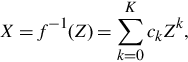
Lee et al. (2013) make the acute observation that the estimates for the exposures Xi from the different images in the stack should be linearly dependent. More formally, the matrix formed with the N exposure images represented as column vectors, [X1,X2,…,XN], should have rank 1. With the matrix O = [Z1,Z2,…,ZN], where the columns are the observed images, the inverse of the CRF g can then be found as
where the operator ⊗ represents an element-wise application of a function. For numerical considerations, rather than minimizing the rank of the matrix, Lee et al. suggest minimizing the ratio of the first two singular values of g ⊗ O (this is also called the condition number). They propose solving
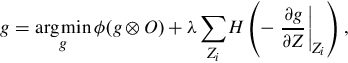
where ϕ(⋅) is the first condition number of a matrix, and H(⋅) is the Heaviside step function, which is 1 if its argument is nonnegative, and 0 otherwise. The second term encourages monotonicity: it adds a penalty that is proportional to the number of points where g is decreasing.
Another interesting approach is the work of Kim et al. (2012). On the basis of their analysis of a large database of JPEG+RAW5 images taken with different cameras and settings, they propose that a single CRF, as traditionally defined and estimated, is not sufficient to explain all of the in-camera processing steps. They observe that cameras perform a gamut mapping that is a function of the scene, or, more specifically, of the “picture style.” Therefore, they propose the following image formation model:
where h(⋅) is the gamut mapping, Ts is the matrix for convection to sRGB, and Tw is the white balance matrix. The key observation is that the gamut mapping, carefully adapted to the scene’s type to improve the visual quality of the JPEG image, can be detrimental to the estimation of the inverse of the CRF; however, they hypothesize that the pixels that are affected the most by gamut mapping are the ones that are highly saturated (ie, in the HSV color space they have a high saturation value), and show that removing them from the computation of the CRF allows a more accurate result to be obtained.
Virtually all the methods described in this section require that the input stack be perfectly registered; in other words, they assume that the underlying irradiance at pixel p is the same across the stack. Grossberg and Nayar (2003a) propose overcoming this constraint by estimating intensity mapping functions (IMFs). The idea is similar to that of comparagrams (Mann and Picard, 1995): IMFs capture how the brightness values change between two images in the stack. However, rather than building the cross-histogram of two images, which implicitly assumes registration, they look at the cumulative histogram of brightness: ![]() , where H is the histogram of the image. The advantage of the cumulative histogram of an image is that it is robust to small motions in the scene. Given the cumulative histogram of two images C1 and C2, it is straightforward to compute the IMF τ1,2:
, where H is the histogram of the image. The advantage of the cumulative histogram of an image is that it is robust to small motions in the scene. Given the cumulative histogram of two images C1 and C2, it is straightforward to compute the IMF τ1,2:
More recently, Badki et al. (2015) proposed an algorithm specifically designed to tackle the problem of radiometric calibration for scenes with significant motion. Their approach builds upon both the work of Grossberg and Nayar (2003a) and the method for radiometric calibration by rank-minimization of Lee et al. (2013). First, inspired by the method of Hu et al. (2012), they extend the method of Grossberg and Nayar to large motions by proposing a new random sample consensus (RANSAC)-based method for computing the IMFs that is robust to such motions. Second, they replace the least-squares optimization for solving for the CRF in Grossberg and Nayar with the rank-minimization scheme of Lee et al. However, the original method of Lee et al. uses artifact-prone, pixel-wise correspondences in the optimization, so Badki et al. reformulated the optimization to replace these correspondences with IMFs. The result is an algorithm that can solve for the CRF even in cases of significant camera and scene motion.
3.3.1.3 Single-image methods for radiometric calibration
The methods we have described thus far assume that multiple images Zi of the same scene are available, essentially allowing one to measure different segments of the CRF. However, radiometric calibration can also be performed on a single image, although with potentially lower accuracy. Single-image methods can be beneficial in the context of stack-based HDR imaging when the assumption that the CRF is the same across the stack is not valid.
Matsushita and Lin (2007) leverage the fact that the different sources of noise in a camera system can be modeled with symmetric distributions: the cumulative noise distribution should then be symmetric as well, and any deviation from the overall symmetry results only from the nonlinearity of the CRF. Therefore, using existing methods to estimate the noise distribution from a single image, they frame the problem of radiometric calibration as
where ξη is a measure of the skewness induced by f to the noise distribution η. Eq. (3.13) essentially states that g should restore the symmetry of the noise distribution that is expected before the CRF is applied to the image.
Lin et al. (2004) propose another single-image method. They observe that, owing to the finite size of the pixels, the irradiance of pixels at the boundary between two uniform regions is a linear combination of the values on either side of the edge. Moreover, moving along a direction orthogonal to the edge in image space should correspond to moving along a line in RGB space only if the CRF is linear. However, if a nonlinear CRF is applied to the pixel values, these linear segments become curved. Therefore, they use the method of Grossberg and Nayar (2003b) to parameterize the CRF, and formulated an optimization problem where the solution for g maximizes the linearity in the RGB space of several segments that cross image edges.
Lin et al. (2004) extended this method to a single, grayscale image based on the same idea: the irradiance values of edge pixels should be a linear combination of the irradiance values of the regions on either side of the edge. However, since color is not available, they look at the histograms of the intensities in patches lying across edges. These histograms should be roughly uniform, because the point spread function, together with the finite pixel size, turns a sharp edge into a smooth gradient. Once again, they formulate an optimization problem where the inverse CRF is the function that maximizes the uniformity of histograms of different “edge” patches.
The methods described in this section are not intended to serve as a complete survey of the range of radiometric calibration methods; rather they are meant to offer insight into the strategies most commonly used. Many other relevant methods have been proposed, such as methods that model and estimate the noise characteristics of the sensor (Tsin et al., 2001; Granados et al., 2010), approaches based on a probabilistic framework (Xiong et al., 2012), and algorithms working with video sequences, where the CRF may also vary from frame to frame (Grundmann et al., 2013).
3.3.2 Merging Multiple LDR Images Into the Final HDR Result
The process of radiometric calibration we described in Section 3.3.1 essentially maps images captured with different exposure times, and processed with nonlinear operators, to the same linear domain. In this domain, an estimate of the irradiance ![]() can be computed as a linear combination of the values of the corresponding pixels across the stack:
can be computed as a linear combination of the values of the corresponding pixels across the stack:
where we do not make the dependency of the weights wi(⋅) explicit because, for different methods, they can be a function of the pixel value Zi(p) or the exposure Xi(p). Eq. (3.14) is at the heart of most methods that merge multiple LDR images into a single HDR image, with the difference between the various methods lying in the actual definition of the weights w. These weights can have a big impact on the quality of the final irradiance estimate because the different images in the stack will, in general, be affected by different amounts of quantization noise, photon shot noise, thermal noise, etc.
Debevec and Malik (1997) observed that the nonlinearity induced by clipping (saturation or underexposure) limits the accuracy with which the true exposure X of these pixels can be recovered. Therefore, they empirically defined a simple triangle function for w that attenuates the contribution of pixels whose exposure is close to either end of the range:
where ![]() is the range of the pixel values. Mann and Picard (1995) adopted a similar solution, but quantified more accurately the quality of the irradiance estimate offered by each image in the stack. Specifically, they propose considering the granularity of the quantization induced by the CRF. Where the CRF is steeper, the mapping from X to digital value Z produces a lower quantization error; conversely, where the CRF is flatter, larger ranges of the exposure axis are mapped to the same digital value. Therefore, they define the weights as
is the range of the pixel values. Mann and Picard (1995) adopted a similar solution, but quantified more accurately the quality of the irradiance estimate offered by each image in the stack. Specifically, they propose considering the granularity of the quantization induced by the CRF. Where the CRF is steeper, the mapping from X to digital value Z produces a lower quantization error; conversely, where the CRF is flatter, larger ranges of the exposure axis are mapped to the same digital value. Therefore, they define the weights as
Note that Eq. (3.16) only accounts for quantization noise and ignores the other sources of noise. Mitsunaga and Nayar (1999) extended the work by Mann and Picard by explicitly considering the SNR in the weight computation:
where, again, g = f−1 and, in the last step of the equation, the noise σX is assumed to be independent of the level itself, and is therefore dropped. As pointed out by Granados et al. (2010), for linear cameras we can write wMN(X) = t, since the rest of the terms are the same in every LDR.
Robertson et al. (2003) use a weighted least squares approach, where the contribution of each pixel to the error is weighted with Mann and Picard’s weight, wMP, from Eq. (3.16):

which can be minimized, leading to the weights:
3.3.2.1 Maximum likelihood estimation
A more theoretically founded approach is to compute the maximum likelihood (ML) estimate of the irradiance ![]() (Tsin et al., 2001; Granados et al., 2010). Given two irradiance estimates Ei(p) = Xi(p)/ti from two different images in the stack, we seek to compute:
(Tsin et al., 2001; Granados et al., 2010). Given two irradiance estimates Ei(p) = Xi(p)/ti from two different images in the stack, we seek to compute:
where we omitted the dependence on the pixel p for clarity. We can assume that the observations are drawn from two independent Gaussian distributions ![]() . We can then write
. We can then write

where we made the common assumption of a uniform prior distribution. Plugging Eq. (3.21) into Eq. (3.20) and taking the logarithm, we can write

We can find the ML estimate for ![]() by setting the derivative with respect to
by setting the derivative with respect to ![]() in Eq. (3.22) to zero:
in Eq. (3.22) to zero:

from which we can see that ![]() . Several methods build on this result by observing that weights should at least account for the uncertainty of the pixel’s value. The first attempt in this direction was the work of Tsin et al. (2001). After modeling white balance as an affine transformation of the exposure X, and calibrating the sensor for photon shot noise and thermal noise, they define the weights as
. Several methods build on this result by observing that weights should at least account for the uncertainty of the pixel’s value. The first attempt in this direction was the work of Tsin et al. (2001). After modeling white balance as an affine transformation of the exposure X, and calibrating the sensor for photon shot noise and thermal noise, they define the weights as
where σ(Z) is the standard deviation of the signal, measured from the residuals of the irradiance estimation. Kirk and Andersen (2006) used the ML weights as well:

Arguably, the most complete noise model was proposed by Granados et al. (2010). They too use the ML weights, but improved on previous work by considering both spatial and temporal noise, the latter being also modeled more accurately than in other approaches. Moreover, they precalibrate the camera noise parameters to avoid polluting the irradiance estimate with the uncertainty of the noise estimation.
3.3.2.2 Winner-take-all merging schemes
A few researchers have proposed a different approach to the generation of an HDR map from a stack of LDR images. Such work is based on the observation that the picture with the longest exposure in the stack is also the one with the smallest quantization noise, and the one impacted by the least photon shot noise (see also Section 3.2). Following this logic, in his work preceding the work of Mann and Picard (1995), Madden (1993) suggested combining the different images in an HDR stack by using the longest, nonsaturated exposure available for each pixel p. A similar approach was proposed by Tocci et al. (2011); however, they also suggest blending the irradiance estimates at the very top and bottom of the useful range of each LDR image to prevent banding artifacts in the transition areas. Additionally, Tocci et al. worked in the Bayer domain to prevent artifacts due to demosaicing when a subset of the color channels saturate, and assessed the reliability of a pixel’s estimate also based on its neighborhood.
3.3.2.3 Exposure fusion methods
The approach to HDR we have described so far consists of radiometric calibration, followed by a merging process that produces the final HDR result. To be displayed on regular monitors, the HDR map needs to be tone mapped. An orthogonal approach is that of fusing the images directly in the nonlinear brightness domain. The most popular method in this category is exposure fusion by Mertens et al. (2007). Their simple and effective method sidesteps the estimation of the exposure values Xi, and blends the digital values Zi directly. To reflect the quality of a pixel value, they define
where ws, the color saturation weight, encourages more vivid colors, wc, the contrast weight, penalizes low contrast, and we, the well-exposedness weight, prefers pixels close to the middle of the range. A naïve application of the method directly to the image may cause visible seams due to abrupt changes in the values of the weights of neighboring pixels. To prevent such artifacts, Mertens et al. decompose the image into a Laplacian pyramid, and combine it with a Gaussian pyramid decomposition of the weight maps to create the final image. Once again, unlike Eq. (3.14), wEF is used in the weighted average of the digital values Zi. Merging images directly in the nonlinear brightness domain has advantages and disadvantages. In general, it creates natural-looking results, whereas the tone mapping procedure required for the standard HDR pipeline often produces unnaturally contrasted pictures. Moreover, artifacts due to misregistration are often attenuated by the weighting process. At the same time, it never produces an actual HDR irradiance map, which can be beneficial for computer vision tasks. Finally, when the difference in brightness between the images in the stack is too large, it can introduce artifacts caused by the Gaussian pyramid decomposition of the weights. Several methods build on this idea to increase computational efficiency (Gelfand et al., 2010), to embed deghosting (Zhang and Cham, 2010; An et al., 2011; Gallo et al., 2015), or simply to propose different weights (Shen et al., 2011).
3.4 Handling Artifacts From Motion During HDR Reconstruction
The algorithms described in the previous section assume the scene to be static and the camera to be steady. However, when the stack of LDR images is captured in the presence of camera or scene motion, the misalignment between different exposures produces ghostlike artifacts in the final HDR result (see Fig. 3.5B). Since this is a common scenario, addressing motion artifacts is an important problem for practical HDR capture. Indeed, there is a large body of research on the subject, some of which we will survey here. These methods are often known as HDR “deghosting” algorithms, because they deghost (or remove ghosting artifacts from) the final HDR result. Readers seeking detailed explanations of the individual algorithms or thorough comparisons are referred to the original articles cited, as well as survey articles in the field (Srikantha and Sidibe, 2012; Hadziabdic et al., 2013; Tursun et al., 2015).

Before we begin, we note that stack-based approaches to HDR reconstruction cannot always recover the actual HDR image when the scene is dynamic, at least not like an actual HDR camera would. For example, consider the situation shown in Fig. 3.6, where the volleyball in front of the bright window occupies different positions across the two-image stack. In the long exposure, which has been selected as the reference, the window is almost entirely saturated and offers no useful detail. Ideally, we would recover this information from the short exposure, which properly captures the scene outside the window. Unfortunately, in the second frame, the ball has moved and blocks part of the view of the window, making it impossible to capture the scene behind it. Because this information is not available in any picture of the stack, we cannot reconstruct an HDR image that would exactly reproduce the structure of the scene as it was when the reference image was captured, as shown in Fig. 3.6C. However, some of the deghosting algorithms we will discuss are able to reconstruct plausible HDR results, even in extreme cases. Furthermore, they offer the only practical way to capture HDR images of dynamic scenes with conventional digital cameras.

Previous deghosting work can be divided into two major categories: (1) rejection-based algorithms and (2) alignment algorithms. Rejection-based algorithms assume the scene to be mostly static and use a rejection technique to eliminate motion artifacts, while alignment algorithms perform some kind of nonrigid registration between the images so that they can be merged to produce the final HDR result. Each kind of algorithm has advantages and disadvantages, which we will discuss at a high level below. Before we begin discussing the two major kinds of deghosting algorithms, however, we note that either approach can first address artifacts from small camera motions through simple, rigid-alignment approaches as described in the next section.
3.4.1 Simple Rigid-Alignment Methods
A simple rigid-alignment preprocess (eg, one using a rotation, translation, or homography matrix to align the images) can often eliminate many of the artifacts from small camera motions, making it easier to deghost images that contain mostly static objects. Of course, such rigid registrations do not address the problem of parallax (caused by camera translation), or artifacts caused by highly dynamic scenes. However, they usually work reasonably well when the camera motion is relatively small and the scene does not undergo significant changes.
To our knowledge, the first method which performed a simple rigid-alignment preprocess is the work of Bogoni (2000), who applied a global affine alignment before his optical flow alignment (we will discuss this method in more detail in Section 3.4.3.1). Another early method is the work of Ward (2003), which targets artifacts from camera translations. To compare the differently exposed images, Ward proposes first converting them into median threshold bitmaps, which are binary images with 1’s for pixels greater than the images’ median. This strategy stems from the observation that median threshold bitmaps from differently exposed images resemble each other more closely than when other potential transformations, such as edge operators, are applied to the images.
One can use median threshold bitmaps to measure the registration quality by simply XORing the pixels of the median threshold bitmaps to see where they are different. The optimal translation is the one that maximizes the number of 1’s in the median threshold bitmap. To minimize the impact of noise induced by the pixels close to the median threshold, Ward excludes the pixels whose distance from the threshold is within the noise tolerance. This process can be accelerated with a pyramidal approach, where the translational alignment is computed on coarse versions of the images and then refined at higher resolutions. This multiscale approach also reduces the chance of convergence to a local minimum.
Tomaszewska and Mantiuk (2007) proposed a different method of rigid alignment by using SIFT to extract key points in each image and finding correspondences between them. They then eliminate spurious matches using RANSAC to estimate the homography that can be used to prewarp the images. These warped images can then be merged by any of the methods described in Section 3.3. In the end, different flavors of methods like these are common preprocessing steps for more advanced algorithms, as we will see in the next section.
3.4.2 Rejection Algorithms for HDR Deghosting
Rejection-based algorithms assume minimal scene motion and a static camera so that only few pixels actually exhibit motion. If the camera shakes slightly, a simple rigid registration process, such as one of those described in the previous section, can be applied as a preprocess to align the images and satisfy this assumption. Since most of the pixels will exhibit no motion under these assumptions, most of the final HDR images can be computed with the standard HDR merging process for static scenes described in Section 3.3. To prevent artifacts at the pixels affected by motion, only the images that are deemed to be static at those locations are combined.
The challenge for these rejection algorithms, therefore, is to detect pixels affected by motion and select from the stack the pixels that can be used in the corresponding locations. These algorithms are usually easy to implement and fairly fast, as they only have to detect motion pixels that deviate from the predicted value. Furthermore, because of their design, they are usually successful at completely removing ghosting artifacts, but sometimes have to compromise on the extent of the dynamic range reconstructed in certain regions.
However, rejection algorithms do have serious shortcomings. Perhaps most importantly, these methods cannot handle moving HDR content since they typically discard from the stack any pixels that contain motion. For example, consider a scene with a moving object whose radiance has a dynamic range too high to be captured by a single image (eg, a moving person who is partly in the shadows and partly under direct sunlight). Rejection-based techniques cannot reconstruct this HDR image correctly, as these methods only merge corresponding pixels across the stack of images, rather than compensating for motion (ie, they do not move content around). In these cases, different portions of the HDR irradiance range may be measured by nonoverlapping regions of the images in the stack, and therefore the values from a single pixel across the stack cannot be combined to get a proper HDR result. Therefore, in general, rejection algorithms have not been as effective in reconstructing HDR results from complex dynamic scenes as the registration-based algorithms we will examine in Section 3.4.3.
Nevertheless, it is useful to study rejection-based techniques because the results they produce are generally not affected by motion artifacts. We can classify rejection-based methods into two categories, which we will describe in the subsequent sections: (1) those that do not select a reference image and try to use information from all images equally (often producing an image from only the static parts of the scene), and (2) those that select an image in the stack as the reference (with the goal of producing an HDR result that resembles this image).
3.4.2.1 Rejection methods without a reference image
Rejection methods that do not define a single reference image are based on the observation that small moving objects tend to affect different regions of the images across the stack. Therefore, if the stack of LDR images is large enough (usually five or more images), a pixel p is likely to capture the irradiance from the static parts of the scene in most of the pictures. Methods from this category then propose a model for how pixel p should behave across the stack if it represented a static object, and discard the values Zi(p) across the stack that do not follow this model, as they are likely to be affected by motion. However, these methods run into the problem that neighboring pixels may come from a different subset of exposures where objects might be in different positions, which would introduce visible discontinuities. To minimize these effects, these algorithms generally identify clusters or groups of pixels that can be drawn coherently from one (or more) of the input LDR images.
One of the first methods to do this was described in Section 4.7 of the book by Reinhard et al. (2005). In this method, the CRF is assumed to be known so that the LDR images Zi can be converted into their corresponding irradiance images Ei. The different images Ei should theoretically be the same, except for noise, saturation, and motion, which may alter some of the pixels’ values from image to image. Therefore, Reinhard et al. propose computing the weighted normalized variance of the values at each pixel p to determine which pixels are affected by motion:

This equation, explained only verbally by Reinhard et al. (2005) and later presented mathematically by Jacobs et al. (2008), uses weights wi to exclude overexposed or underexposed pixels from the computation as their divergence from the true irradiance may bias the estimate of the variance. Note that unlike traditional variance, the variance in Eq. (3.27) is normalized to the actual size of the signal.
The key observation is that when one is looking across the image stack, pixels that are not affected by motion should have a smaller variance than those that measure irradiance from different objects. Of course, one could set a simple threshold for this variance to distinguish between these two cases. However, this naïve approach has the problem that the image would suffer from discontinuity artifacts when neighboring pixels are selected from different images with different objects.
To avoid this problem, rejection methods that do not define a reference image must group pixels together into larger clusters, where all the pixels in a cluster are drawn coherently from the same image in the stack. In the particular case of Reinhard et al. (2005), morphological operators such as erosion and dilation are used to grow the binary image after thresholding of the variance to create larger, contiguous regions that are identified to have motion. To decide which exposure to use in each region, they generate a histogram of irradiance values in each region and find the maximum value that is not in the top 2%, which they consider to be outliers. They then find the longest exposure that still includes this maximum value within its valid range, and interpolate between this exposure and the original HDR result using the per-pixel variance as a mixing coefficient. In this way, pixels with lower variance across the stack will use the original HDR result, while pixels with larger variance will use the single exposure. This algorithm is able to produce deghosted images and, at the same time, ensure that each region is drawn coherently from one exposure.
In another method, Eden et al. (2006) first use a SIFT-based feature registration technique to align the input images in the presence of varying exposure levels. Once the stack has been aligned, they map the images to the irradiance domain, where they draw each pixel of the final composite from one of the input images. This is done in two steps. In the first step, they use a subset of the aligned input images to create a reference panorama that covers the full angular extent of all the inputs using graph cuts (Boykov et al., 2001). However, because of overexposure or underexposure this reference image could have areas of missing information, so they introduce detail from images that are better exposed while solving for a smooth transition between regions in a second pass. This problem is minimized via max-flow graph cut to produce the final result, which can be smoothed out to remove any remaining seams.
The approach of Khan et al. (2006) attempts to compute a ghost-free image through several iterations of kernel density estimation that modify the blending weights wi of Eq. (3.14), by assuming that background (static) pixels are the most common. Essentially, they compute the probability that a given pixel is part of the background, and use this weight when blending so pixels from dynamic objects (and not the background) get a smaller weight. To do this, they represent each pixel in the stack of images with a five-dimensional vector xi(p), where i is the index of the image in the stack and p is the pixel location. This vector contains the three LDR color channels of the pixel value (in Lab space) as well as the coordinates of the pixel on the image.
For a given pixel p, they select all pixels yj(q) in its 3 × 3 neighborhood over all the images in the stack, denoted by ![]() . Note that the pixels at position p across the stack are not included in this neighborhood. They begin by assuming that all yj(q) are equally likely to be part of the background. The probability that a pixel p belongs to the background B (given by P(xi(p) | B)) can then be calculated with a kernel density estimator:
. Note that the pixels at position p across the stack are not included in this neighborhood. They begin by assuming that all yj(q) are equally likely to be part of the background. The probability that a pixel p belongs to the background B (given by P(xi(p) | B)) can then be calculated with a kernel density estimator:

where the kernel KH is a five-dimensional multivariate Gaussian density function, and the weight wj,q indicates the probability of the pixel belonging to the background. For the first iteration, these weights are initialized to a “hat” function similar in spirit to that of Debevec and Malik (1997). For subsequent iterations, the value of the weights can be set to the probability that the pixel belongs to the background, as computed by Eq. (3.28) in the previous iterations. However, each time the newly computed weights are multiplied by the initial weights from the hat function to continually diminish the probability that pixels that are overexposed or underexposed are used in the final estimates. On convergence, the weights are plugged into Eq. (3.14) to merge the LDR images into an HDR result.
Jacobs et al. (2008) extended the deghosting algorithm of Reinhard et al. (2005) in several ways. First, they prealign the images as in the earlier work of Ward (2003), but in this case they iteratively solve for the translation and rotation that maximizes the XOR score between the two median threshold bitmaps. In the second stage, they replace the variance metric of Eq. (3.27) with a local entropy measure that indicates movement in the scene. Specifically, they measure the local entropy at each pixel in the LDR image Zi by looking at the pixel values z within a two-dimensional window around pixel p:
where the probability function P(Z = z) is computed from the normalized histogram of the intensity values of pixels within the window. Using these entropies, they compute an uncertainty image U, which is the local weighted entropy difference between the images:

where ![]() , and weights wi(p) and wj(p) are computed with Debevec and Malik’s triangle function in Eq. (3.15), with
, and weights wi(p) and wj(p) are computed with Debevec and Malik’s triangle function in Eq. (3.15), with ![]() and
and ![]() . The intuition is that static regions would have similar local entropy measures across the LDR images, even if they are near edges, which might increase the variance because of slight camera motions. This method also does not need a priori knowledge of the CRF, as the entropy measurement can be done in the LDR domain. As with previous methods, this uncertainty image is thresholded and the resulting binary image is eroded and dilated to produce contiguous regions that are affected by motion. At this point, each region is filled with values from one of the irradiance images Ei that is not overexposed or underexposed in that region and is blended with the original HDR value to avoid artifacts at the borders.
. The intuition is that static regions would have similar local entropy measures across the LDR images, even if they are near edges, which might increase the variance because of slight camera motions. This method also does not need a priori knowledge of the CRF, as the entropy measurement can be done in the LDR domain. As with previous methods, this uncertainty image is thresholded and the resulting binary image is eroded and dilated to produce contiguous regions that are affected by motion. At this point, each region is filled with values from one of the irradiance images Ei that is not overexposed or underexposed in that region and is blended with the original HDR value to avoid artifacts at the borders.
Sidibe et al. (2009) observed that the value of pixel p across the stack should increase with the exposure time, since the camera response curve is monotonically increasing: Zi(p) ≤ Zj(p) if ti < tj. Therefore, they propose identifying regions where this order relation is broken at least once as ghosted regions. Of course, there might be motions that preserve this order which would not be detected. In the ghosted regions, they use the input images that they deem to have captured the background, which is assumed to appear in most of the images. To do this, they effectively compute the histogram of irradiance values at each ghosted pixel and compute the mode of this distribution, which is the value that appears the most often. The mode is assumed to be the background and the values are merged (ignoring pixel values close to saturation or zero) to form the final HDR image. To have enough samples at each pixel to compute the mode, they require at least five images in the stack.
In another approach, Pece and Kautz (2010) first compute median threshold bitmaps for each image in the stack as proposed by Ward (2003) and accumulate these binary maps for each pixel over all the exposures. Values that are neither 0 nor N are considered motion, and the morphological operators of dilation and erosion are applied to this result to generate the final motion map. Pece and Kautz present results they obtained using exposure fusion (Mertens et al., 2007), where they select the best available exposure for each of the clusters in the motion map to produce their results.
Zhang and Cham (2012) presented a technique similar to exposure fusion (Mertens et al., 2007) (see Section 3.3.2.3) because they fuse the images without generating an HDR image first, but use a novel consistency metric that uses the image gradient to detect movement. To begin, they compute the magnitude Mi(p) and direction θi(p) of the gradient around every pixel of each image in the stack. Next, they observe that the magnitude of the gradient can be used to determine saturated or underexposed pixels, as these regions typically have lower gradient magnitude. Therefore, they propose a visibility measure that indicates how well exposed and visible a particular pixel is:

where the ε is a small value (eg, 10−25) to avoid division by zero. Finally, they observe that the gradient direction can serve as a consistency measure to detect motion across the exposure stack because of its invariant property over different exposures. Therefore, they compute the gradient direction difference of the ith image with respect to the jth image as follows:

where ![]() is the set of offsets of the pixels in an M × M square neighborhood around pixel p. With this, a consistency score Si can be computed for every image. One does this by accumulating a Gaussian weight for each pixel based on the difference of its gradient direction across the stack:
is the set of offsets of the pixels in an M × M square neighborhood around pixel p. With this, a consistency score Si can be computed for every image. One does this by accumulating a Gaussian weight for each pixel based on the difference of its gradient direction across the stack:

Given these scores, a consistency score for each pixel p in the stack image i can then be calculated as

where αi(p) is simply 1 if the pixel is well exposed and 0 if it is not. Here, we use the term “well exposed” to define a pixel whose value is in the middle of its range — say, between 0.1 and 0.9 in a normalized pixel value range. These consistency scores can then be used to compute the final weights for the fusion process (Eq. 3.26):

The final image can then be fused without the need for tone mapping, but does not produce a true HDR result.
Granados et al. (2013) propose using a noise-aware model to determine whether the image stack values for a particular pixel are consistent, which means that they measure the same static irradiance. They observe that for a pixel in a static region, the exposure values across the stack should all be within an error margin based on the noise of the imaging system. Therefore, rather than using an arbitrary threshold to detect motion, they characterize the noise in the imaging system (both shot noise and readout noise) as a Gaussian distribution, which enables them to determine the probability that the difference between two pixel values is caused by scene motion or noise. This idea can be extended to the N images in the stack to produce consistent subsets, which will not introduce ghosting artifacts when combined.
Once these consistent subsets have been identified, the next challenge is to ensure that neighboring pixels are drawn coherently from the subsets to avoid artifacts. To do this, they pose the irradiance reconstruction problem as a labeling problem, solved by minimizing an energy function with two terms. The first, a consistency term, encourages the pixels to be selected from consistent subsets of the image to reduce ghosting. The second is a prior term that penalizes incoherency across neighboring pixels by enforcing that neighboring pixels should be drawn from the same consistent subset. They solve this labeling problem using the expansion-move graph-cuts algorithm and then merge the consistent sets at each pixel to produce the final HDR result. However, despite this graph-cut optimization, their method still cannot always guarantee a semantically consistent result, and thus it requires a manual intervention to resolve remaining issues.
Finally, Oh et al. (2015) recently proposed a clever rank minimization strategy to solve for the final HDR image. They begin by assuming that there are two kinds of motion between the images in the stack. The first is global motion due to camera movement, which they assume can be modeled with a homography. The second is local motion, which they want to eliminate, and is caused by the nonrigid movement of objects in the scene. Their key observation is that if global motion is accounted for, the stack of exposure images X1,…,XN should be linearly dependent. In other words, barring local motion, saturation, or noise, the globally aligned exposure images would simply be scaled versions of E (ie, Xi = E ⋅ ti). Therefore, they attempt to eliminate motion artifacts by enforcing that the matrix whose columns are the input LDR images should be of rank 1 (ie, all columns should be linearly dependent).
Oh et al. first account for the global motion by modeling the hypothetical process of capturing “globally aligned” LDR source images, as if the camera were not moving. This can be written as ![]() , where
, where ![]() are the LDR images that would have been taken with a static camera,
are the LDR images that would have been taken with a static camera, ![]() is the ideal exposure image that contains only static scene information, and ηi is a “noise” term representing the local motion in the scene. Since we can apply a homography operator ° hi to perform global alignment on each of the inputs Zi, we can write
is the ideal exposure image that contains only static scene information, and ηi is a “noise” term representing the local motion in the scene. Since we can apply a homography operator ° hi to perform global alignment on each of the inputs Zi, we can write ![]() . Once the camera has been calibrated so that its response curve is linear (see Section 3.3.1), the capture process can be modeled as
. Once the camera has been calibrated so that its response curve is linear (see Section 3.3.1), the capture process can be modeled as
We can then vectorize the terms in this equation and combine them into matrices using all of the N captured images: Z °h = X + η. Since all the columns of X are simply scaled versions of the static scene irradiance E, it is a rank 1 matrix. At the same time, η is sparse if we assume that most of the scene is static and only a few areas are affected by motion. Therefore, the problem of removing motion artifacts from the HDR image is equivalent to the problem of solving for a rank 1 matrix X and sparse matrix η through the following optimization:

Here, ![]() is the sum of the singular values from the second to the last6 which measures the rank of the matrix. The L1 norm
is the sum of the singular values from the second to the last6 which measures the rank of the matrix. The L1 norm ![]() ⋅
⋅![]() 1 is a measure of sparsity, and the weighting coefficient λ balances the contribution of the two terms. This constrained optimization problem can be solved with augmented Lagrange multipliers (Peng et al., 2012), where the problem is divided into three different subproblems for X, η, and h and minimized iteratively.
1 is a measure of sparsity, and the weighting coefficient λ balances the contribution of the two terms. This constrained optimization problem can be solved with augmented Lagrange multipliers (Peng et al., 2012), where the problem is divided into three different subproblems for X, η, and h and minimized iteratively.
As discussed earlier, rejection-based algorithms have their drawbacks, but this subset of algorithms that do not specify a reference image have additional problems. For example, they can often produce images that contain duplicate objects or other artifacts, because the semantic meaning of objects is lost when the consistent sets computed in neighboring pixels are not coherent. These artifacts typically require a manual correction. Furthermore, since they typically strive to use only “background” pixels from each image, rejection methods of this type will suppress dynamic objects from the HDR result.
Finally, because these algorithms produce images that do not adhere to a ground truth reference (ie, an HDR picture taken at a specific moment in time), they cannot be easily extended to the capture of HDR video. The reason for this is twofold. First, they do not guarantee temporal continuity since each frame is individually computed, and may use a pixel cluster that is not temporally coherent with the neighboring frames. Second, even if temporal coherency could be enforced, the fact that dynamic objects are usually suppressed defeats the purpose of taking a video in the first place.
3.4.2.2 Reference-based rejection methods
The algorithms in this category select a single image from the stack as the reference and use it as the foundation of the final image. In other words, the HDR result will be geometrically consistent with this reference, at least in the parts where it is well exposed. The other images in the stack will be tested against the reference, and pixels deemed to have been affected by motion will be rejected. For regions where all the images in the stack are rejected, the HDR result would be reconstructed with use of only the reference.
One of the first examples of these algorithms is the work of Grosch (2006), which takes two differently exposed images and first aligns them using a variant of the method proposed by Ward (2003), extended to consider both translation and rotation. He then computes the CRF on the largely aligned images using the method of Grossberg and Nayar (2003a), and uses the first image (the reference) to predict the estimated values in the second:
If the predicted color ![]() is beyond a threshold from the actual color in the second image (ie,
is beyond a threshold from the actual color in the second image (ie, ![]() ), the algorithm assumes that Z2(p) would introduce motion artifacts, and falls back to using only the first image at these locations. This produces an artifact-free result because it largely follows the reference, and has the advantage that it does not need a priori knowledge of the CRF. However, if the scene contains large moving objects, then the radiometric calibration step could fail as well, unless a more robust calibration procedure, such as the algorithm of Badki et al. (2015), is used (see Section 3.3.1.2).
), the algorithm assumes that Z2(p) would introduce motion artifacts, and falls back to using only the first image at these locations. This produces an artifact-free result because it largely follows the reference, and has the advantage that it does not need a priori knowledge of the CRF. However, if the scene contains large moving objects, then the radiometric calibration step could fail as well, unless a more robust calibration procedure, such as the algorithm of Badki et al. (2015), is used (see Section 3.3.1.2).
Gallo et al. (2009) propose a similar approach. They first define the reference as the image in the stack with the fewest overexposed and underexposed pixels; they then compare the values of the pixels of the different images in the stack against it. They perform the comparison in the log-irradiance domain, where the following relationship holds:
where the dependence on pixel p is omitted for clarity. Pixels whose exposure Xi(p) is farther than a threshold from the value predicted by Eq. (3.39) belong to moving objects. However, for increased robustness, rather than working directly with pixels, Gallo et al. propose working with patches; a patch from the ith image in the stack is merged with the corresponding patch in the reference if the number of its pixels obeying Eq. (3.39) is above the threshold. The patches are defined on a regular grid; because two neighboring patches in the reference image can be merged with a different subset of patches from the stack, visible seams may exist at the patches’ boundaries. To address this issue, the patches are blended with a Poisson solver (Pérez et al., 2003).
Raman and Chaudhuri (2011) extended the work of Gallo et al. (2009) by replacing squared patches with superpixels, which are inherently more edge aware. However, rather than computing the HDR irradiance map, they fuse the images directly using their nonlinear digital pixel values. To begin, they compute the weighted variance proposed by Reinhard et al. (2005), see Eq. (3.27), to identify the pixels that may have measured irradiance from moving objects. Then, using only the pixels that are deemed to have captured static objects, they fit fourth-order polynomials to create a set of N − 1 IMFs that map the pixel values of each exposure in the stack to the reference.
In the next step, all the images but the reference are segmented into superpixels with homogeneous color and texture. The idea is to blend the superpixels that are static with respect to the reference with the well-exposed reference information. To identify a superpixel as static, the authors use the IMF and compare its pixels with those of the superpixel in the reference; to make the process more robust to noise they also threshold the distance of each pixel from the predicted value. If 90% of the pixels are within this threshold, then the superpixel is considered to be static with respect to the reference. These static superpixels are then decomposed into 6 × 6 patches with an overlap of one pixel on each edge. The patches with more than 90% of pixels within the static superpixel are considered static as well, and their gradients are merged by use of a Gaussian weighting function based on exposure. Finally, a Poisson solver is used to reconstruct the final color information from the gradients (Pérez et al., 2003).
Wu et al. (2010) propose a set of criteria for detecting moving pixels. First, they use a criterion that ensures that the pixel values are monotonically increasing as the exposure time is lengthened, similar to the earlier work of Sidibe et al. (2009). Next, they use a criterion similar to that of Grosch (2006) that compares a pixel’s value with that predicted from another exposure after compensation for the CRF and the exposure time ratio. If a pixel violates any of these criteria, then it is considered to be affected by motion. The final motion map is generated by use of the morphological operators, such as opening and closing. Once the pixels affected by motion have been identified, Wu et al. proceed to compute the final HDR image. Specifically, they select image k as a reference and use it to fill in the pixels affected by motion in the neighboring images k − 1 and k + 1 with the value predicted by the camera response curve as in Eq. (3.38). These new images are then used to predict the next images, and so on until the entire stack has been processed. Finally, they correct boundary artifacts near the edges of the regions in the motion map by convolving the images with a low-pass kernel, and using the result to replace the values calculated originally in these regions. The HDR image is then computed with the standard merging equation (Eq. 3.14).
Heo et al. (2010) first globally aligned the images in the stack with the reference image using a homography estimated with SIFT features using RANSAC. Next, N − 1 joint histograms are computed between the values in the reference and those in the other images. These histograms are then converted into smooth joint probability distribution functions through a Parzen windowing process using a 5 × 5 Gaussian filter followed by a normalization to enforce that the subtended area sums to 1. Pixels in the other images in the stack with a joint probability less than a fixed threshold are labeled as ghost pixels. This simple thresholding of the joint probability to determine ghost regions can be very noisy, however, so Heo et al. further refine the ghost regions using an energy minimization that enforces smoothness between neighboring pixels, and which is solved with use of graph cuts.
The refined ghost regions can be used to compute new joint histograms that are not affected by motion artifacts; therefore, the algorithm iteratively alternates between computing the joint probability distribution functions and detecting the ghost regions. The pixels not affected by motion are then used to compute the CRF with the method of Debevec and Malik (1997). To further reduce artifacts, this CRF is used to refine the radiance values of all the pixels in the other images in order to make their values more consistent with the reference image. Finally, the different exposures are blended to generate the final HDR result with a weighted filtering step. These weights are computed by application of a bilateral filter (Tomasi and Manduchi, 1998) to all the samples in a patch around a pixel, with use of a global intensity transfer function to compare the differently exposed pixel values.
Rejection-based methods that use a single reference image generally reduce or completely remove ghosting artifacts from the final HDR image. They do, however, have some of the shortcomings of all the rejection-based methods we discussed earlier, such as not being able to handle dynamic HDR content. Furthermore, if the regions where the reference is overexposed or underexposed are large, these algorithms could have problems recovering the full dynamic range because of their heavy reliance on the reference; see Fig. 3.7.

3.4.3 Nonrigid Registration Algorithms for HDR Deghosting
Rather than simply rejecting content that could generate ghosting, one can compensate for motion by means of nonrigid registration. To do this, two kinds of algorithms have been proposed: (1) algorithms based on a flavor of optical flow to align the images, and (2) algorithms based on patch-based synthesis. Note that while nonrigid registration algorithms have the potential to preserve a larger dynamic range from the stack, they tend to introduce objectionable artifacts when the estimation of the displacement between the images fails. This is particularly true for flow-based algorithms, which we will discuss first.
3.4.3.1 Optical flow and correspondence registration methods
Bogoni (2000) presented perhaps the earliest known method to register a stack of images for HDR reconstruction. First, he applies an affine motion estimation to globally align the images. This process, based on earlier work on registration for image mosaics (Hansen et al., 1994), operates in a multiresolution fashion from coarse to fine, using a Laplacian pyramid scheme. At each iteration, the optical flow field is computed from one image to another by means of local cross-correlation analysis, and then an affine motion model is fit to the flow field by weighted least-squares regression. The affine transform is then used to warp each image to align it roughly with the reference. At this point, a second step performs unconstrained motion estimation with optical flow between each source image and a predefined reference. This resulting field is used to warp the individual sources to compute the final registration with the reference.
Jinno and Okuda (2008) propose addressing the problem of ghosting with Markov random fields. After selecting the reference image, they estimate three arrays (the same size as the images) for each of the other images in the stack. The first is a displacement field d, and the second is a binary occlusion field o that indicates the parts of the reference that are occluded in the second image. This is computed by thresholding the maximum search distance for the displacement field: if a pixel cannot be found in a neighborhood ![]() around a given pixel that has a luminance within a specific threshold, then pixel p is considered occluded. The third is a saturation field, a binary mask that keeps track of the regions where the second image is overexposed or underexposed. Since these arrays are spatially coherent, they can be modeled as Markov random fields and computed with use of Bayes rule as an estimation problem that finds the most probable fields d, o, and s given observed images Zref and Zi:
around a given pixel that has a luminance within a specific threshold, then pixel p is considered occluded. The third is a saturation field, a binary mask that keeps track of the regions where the second image is overexposed or underexposed. Since these arrays are spatially coherent, they can be modeled as Markov random fields and computed with use of Bayes rule as an estimation problem that finds the most probable fields d, o, and s given observed images Zref and Zi:

This problem is analogous to that of finding ![]() , which they approximate by first finding s through thresholding, and then iteratively solving for d and o. Once they have these fields, they can use them during the merging stage to produce the final HDR result.
, which they approximate by first finding s through thresholding, and then iteratively solving for d and o. Once they have these fields, they can use them during the merging stage to produce the final HDR result.
Zimmer et al. (2011) align images in the stack with a specified reference using an energy-based optical flow optimization that is more tolerant to changes in exposure. To achieve this invariance, they define an energy function that leverages the gradient constancy, similar to that of Brox et al. (2009) and that of Brox and Malik (2011). Specifically, for each image i in the stack they compute a dense displacement field ui(p) = [ui(p),vi(p)]T that specifies an offset at every pixel by minimizing an energy function of the form
where D(ui(p)) is the data term that tries to align the image with the reference, and S is the smoothness term (regularizer) that encourages smooth flow in places where the reference image is unreliable (ie, overexposed or underexposed). Because the brightness constancy across the stack is violated in this application, they propose that the data term D(ui(p)) should try to match the gradient of the offset region in image Zi with that of the reference:

where Ψ is regularized L1 norm ![]() and nx and ny are normalization factors. For the smoothness term S(∇δpi(p)), they use a regularizer based on total variation:
and nx and ny are normalization factors. For the smoothness term S(∇δpi(p)), they use a regularizer based on total variation:
The energy equation (Eq. 3.41) is then optimized by a semi-implicit gradient descent scheme, and the final flows are used to warp each of the input images in the stack, which are then merged with use of the method of Robertson et al. (1999).
Later, Hu et al. (2012) proposed using the patch-based, nonrigid dense correspondence method of HaCohen et al. (2011) to compute dense correspondences between the reference image and the other images in the stack, called the source images. They then use this correspondence field to warp pixels in the source images to match the appearance of the reference. However, because of occlusions and disocclusions, as well as brightness changes, the correspondences are generally incomplete; this can result in “holes” (ie, regions where the pixels’ values are undefined).
To address this problem, Hu et al. first propose a robust strategy to estimate the IMFs (Grossberg and Nayar, 2003a) using the known pixel correspondences. For each hole in the warped source, they then attempt to paste the pixels from the original source image; however, to compensate for motion, they first apply a local projective transformation to align them with those in the reference. To ensure that the pasted pixels cause no artifacts, Hu et al. take a bounding box larger than the hole to be transformed and pasted. If the pixels within the box, but outside the hole, do not match, the region is considered to be affected by motion. In these cases, the pixels are pasted directly from the reference after their brightness values have been appropriately corrected with the estimated IMF.
Another method based on a flavor of optical flow is the approach of Gallo et al. (2015). The method is based on the observation that modern cameras offer fast bursts modes, which make arbitrarily large displacements unlikely. Therefore, instead of computing the optical flow at each pixel, they suggest computing it only at sparse locations, and then to propagate it to the rest of the pixels. Specifically, there are four stages to the algorithm.
Gallo et al. first describe a novel method to find and match corners across two images in the stack, one chosen to be the reference and the other being the source image. Their corners are based on the changes of average brightness around different pixels, which can be computed efficiently with integral images. The second stage identifies and removes matches that are either incorrect or belong to structures that move in a highly nonrigid fashion. To achieve this, Gallo et al. observe that good matches should be locally consistent with a homography, and propose a modification of the RANSAC algorithm to isolate those that are not. The set of matches that are both correct and rigid offers an estimate of the flow at sparse locations, which can be propagated to the rest of the pixels with use of the reference image as a guide to an edge-aware diffusion algorithm. With the dense flow, the source image can be warped to be geometrically consistent with the reference. However, to account for possible errors in the flow propagation, Gallo et al. modify the algorithm of Mertens et al. (2007), see Section 3.3.2.3, by adding a fourth weight. Specifically, they use the structural similarity index proposed by Wang et al. (2004) to account for the quality of the registration at different locations, and reduce the contribution of regions that are not correctly registered. For a pair of five-megapixel images, Gallo et al. report execution times of less than 150 ms on a desktop computer and less than 700 ms on a commercial tablet computer. For reference, the methods described in Section 3.4.3.2 are several orders of magnitude slower. As mentioned before, this large speedup is possible thanks to the observation that arbitrarily large displacements are unlikely when the stack is captured in a fast burst.
Compared with rejection-based approaches for HDR reconstruction, these alignment methods, which rely on correspondences between the different images in the stack, have the advantage that they can move content around. This allows them to handle dynamic objects with HDR illumination. However, finding reliable correspondences, especially in cases of complex motion and deformation, is quite difficult and can introduce new artifacts. These problems can largely be resolved by use of the patch-based synthesis methods discussed next.
3.4.3.2 Patch-based synthesis methods
The most successful kind of HDR deghosting algorithms are perhaps those that align the stack of images together by using patch-based synthesis to generate plausible images that are registered to the reference (Sen et al., 2012; Hu et al., 2013; Kalantari et al., 2013). Indeed, a recent state-of-the-art report on HDR deghosting techniques has shown that these algorithms produce the best results for general scenes (Tursun et al., 2015). These methods can also be considered a new kind of algorithm (different from the rejection and registration algorithms we have discussed) because they can solve for the aligned images and the HDR reconstruction simultaneously. Although patch-based synthesis had previously been shown to be very powerful for various computational imaging tasks (such as image hole filling (Wexler et al., 2007), image summarization and editing (Simakov et al., 2008; Barnes et al., 2010), morphing (Shechtman et al., 2010), and finding dense correspondences between images (HaCohen et al., 2011)), these new methods apply it to HDR reconstruction by posing the problem as an energy optimization.
To use patch-based synthesis for HDR reconstruction, the two independent methods of Sen et al. (2012) and Hu et al. (2013) make similar observations: after registration, each image Zi from the stack should look as if it were taken at the same time as the reference Zref, but should be photometrically consistent with the original Zi, thereby capturing all of the additional dynamic range information contained in the original image.
Sen et al. (2012) propose doing this using a new optimization equation that codifies the objective of reference-based HDR reconstruction algorithms: (1) to produce an HDR image that resembles the reference in portions where the reference is well exposed, and (2) to leverage well-exposed information from other images in the stack in places where the reference is not well exposed. This results in what they call the HDR image synthesis equation, which contains two terms:

The first term states that the ideal HDR image E should be close in an L2 sense to the LDR reference Zref mapped to the linear irradiance domain. This should be done only for the pixels where the reference is properly exposed, as given by the αref(p) term, which is a trapezoid function in the pixel intensity domain that favors intensities near the middle of the pixel value range.
In the parts where the reference image Zref is poorly exposed as indicated by the 1 − αref(p) term, the algorithm draws information from the other images in the stack using a novel multisource bidirectional equation EMBDS that extends the bidirectional similarity metric of Simakov et al. (2008):

The original function of Simakov et al. takes a pair of images (source S and target T) and ensures that all of the patches (small blocks of pixels) in S can be found in T (first term, called “completeness”) and vice versa (second term, called “coherence”). Note that the coherence term ensures that the final target does not contain objectionable artifacts, as these artifacts are not found in the original source.
However, Eq. (3.45) does not work for HDR reconstruction directly; sometimes content that should be visible in the ith exposure when “aligned” with the reference exposure might be occluded in Zi and needs to be drawn from a different image. So rather than using a pairwise bidirectional similarity metric, Sen et al. introduce a multisource bidirectional similarity metric EMBDS that draws information from all the images in the stack simultaneously.
To optimize Eq. (3.44), Sen et al. introduce auxiliary variables ![]() that represent the different LDR images in the stack after they have been aligned with the reference. This equation can then be solved with an iterative, two-stage algorithm that solves for the
that represent the different LDR images in the stack after they have been aligned with the reference. This equation can then be solved with an iterative, two-stage algorithm that solves for the ![]() and E simultaneously:
and E simultaneously:
Stage 1: The algorithm first solves for the aligned LDR images ![]() with a bidirectional search-and-vote process (Simakov et al., 2008) accelerated by PatchMatch (Barnes et al., 2009). This process draws information into each of the aligned LDR images from the entire stack, which has been adjusted to match the corresponding exposure level. To produce images aligned with the reference, the irradiance image E from the previous iteration (which has been injected with the reference in step 2) is used as the initial target for the search-and-vote process.
with a bidirectional search-and-vote process (Simakov et al., 2008) accelerated by PatchMatch (Barnes et al., 2009). This process draws information into each of the aligned LDR images from the entire stack, which has been adjusted to match the corresponding exposure level. To produce images aligned with the reference, the irradiance image E from the previous iteration (which has been injected with the reference in step 2) is used as the initial target for the search-and-vote process.
Stage 2: Next, the algorithm optimizes for E by merging the aligned images ![]() using a standard HDR merging process (Section 3.3) and then injects the portions of the reference image where it is well exposed into the result.
using a standard HDR merging process (Section 3.3) and then injects the portions of the reference image where it is well exposed into the result.
Once the new E has been computed, it is used to extract the new image targets for the next iteration, and the algorithm goes back to stage 1. These two stages are performed at every iteration of the algorithm until it converges. Furthermore, as is common for patch-based methods such as this (eg, Simakov et al., 2008), this core algorithm is performed at multiple scales, starting at the coarsest resolution and working to the finest. Once the algorithm has converged, it returns both the desired HDR image E and the “aligned” images at each exposure ![]() . A result produced with this algorithm is shown in Fig. 3.8. This algorithm was later extended by Kalantari et al. (2013) to reconstruct HDR video, as described in Chapter 4.
. A result produced with this algorithm is shown in Fig. 3.8. This algorithm was later extended by Kalantari et al. (2013) to reconstruct HDR video, as described in Chapter 4.

 ), computed by the algorithm. (C) Tone-mapped HDR result after the reconstruction. Images courtesy of Sen et al. (2012).
Hu et al. (2013) propose a different patch-based synthesis algorithm, which, unlike the algorithm of Sen et al., does not require the camera calibration curve to be known a priori. Specifically, they calculate the aligned images ![]() as
as
where u is the displacement field that “warps” image Zi to match the geometric appearance of the reference, and τ is the IMF between the source image Zi and the reference Zref. In Eq. (3.46), the first term, Cr for “radiance consistency,” encourages the aligned image ![]() to be geometrically consistent with the reference, Zref:
to be geometrically consistent with the reference, Zref:
Note that both the images and their gradients are accounted for in Eq. (3.47). The second term in Eq. (3.46), Ct, is what Hu et al. call the “texture consistency” term:

where k is a normalization factor. The texture consistency term enforces similarity between the patch around pixel p in the warped source, ![]() , and the corresponding patch in the source image,
, and the corresponding patch in the source image, ![]() . This helps enforce that the synthesized content is plausible and free of artifacts.
. This helps enforce that the synthesized content is plausible and free of artifacts.
Hu et al. tackle this optimization iteratively using a coarse-to-fine approach, which helps in two ways. First, it prevents the optimization from falling in a local minimum. Second, it allows the algorithm to deal with large oversaturated or undersaturated regions: a patch that is entirely saturated at the finest level could include information from neighboring nonsaturated pixels at coarser levels, thus allowing information to propagate inward. To do this, they propose an iterative, three-stage algorithm:
Stage 1: First, they estimate τ using the intensity histograms of the images (Grossberg and Nayar, 2003a) at the coarsest level of the pyramid and initialize ![]() for the same level. The displacement u, which appears only in Ct, can then be estimated with PatchMatch (Barnes et al., 2009).
for the same level. The displacement u, which appears only in Ct, can then be estimated with PatchMatch (Barnes et al., 2009).
Stage 2: In a second step, they propose refining the estimate of ![]() by minimizing Cr. However, for the areas where the reference image is overexposed or underexposed, they average τ(Zref(p)) with the corresponding location in the source image Zi(p + u(p)) with a weight that accounts for how likely the latter is to become overexposed or underexposed in the reference image.
by minimizing Cr. However, for the areas where the reference image is overexposed or underexposed, they average τ(Zref(p)) with the corresponding location in the source image Zi(p + u(p)) with a weight that accounts for how likely the latter is to become overexposed or underexposed in the reference image.
Stage 3: In the third and last step, with the new ![]() , they refine the IMF, τ. Moving to the next finer level, they leave τ unchanged and linearly interpolate u. The latent image
, they refine the IMF, τ. Moving to the next finer level, they leave τ unchanged and linearly interpolate u. The latent image ![]() , instead, is initialized with a weighted average of τ(Zref) and Zi(p + u(p)).
, instead, is initialized with a weighted average of τ(Zref) and Zi(p + u(p)).
Results from this approach can be seen in Fig. 3.9.

 ,
,  ,
,  ) computed by the algorithm. (C) Tone-mapped HDR result after the reconstruction. Images courtesy of Hu et al. (2013).
As discussed earlier, these patch-based synthesis methods have the advantage that they work very well for scenes with complex, arbitrarily large motion where other algorithms would normally fail. However, they are expensive and require considerable time and hardware resources for evaluation: the reference implementations provided by Hu et al. take more than 1 min for VGA images. Furthermore, although they can produce plausible results, they are only hallucinating the final result as compared with the true HDR result that would have been captured by a hypothetical HDR camera.
3.5 Conclusion
In this chapter, we have examined approaches to capture HDR images and video by taking a stack of multiple images at different exposure settings. We began by studying algorithms for metering, which set the exposure levels for the different images in the stack. Next, we studied the process of merging the LDR images into a final HDR result, which included a radiometric calibration process (to compute the irradiance images from the original pixel values) and merging schemes (which compute the weights of the different irradiance images to compute the final HDR). Finally, we examined algorithms developed to handle artifacts from motion when one is capturing stack-based HDR images, which included rejection algorithms and registration algorithms.