
Mechanical
8.1 Guidance
Mechanics is the branch of physics concerned with the motions of objects and their response to forces. Modern descriptions of such behaviour begin with a careful definition of such quantities as displacement (distance moved), time, velocity, acceleration, mass and force.
8.1.2 Introduction
There is often a tendency to underestimate the effect that the mechanical environment can have on the reliability of equipment, especially the effects of vibration and shock.
8.1.2.1 Mechanical stresses (shocks and vibration)
Mechanical stresses are normally attributed to a moving mass and there is often a tendency to underestimate the effect of the mechanical environment on the reliability of static installations. Experience suggests, however, that vibrations and shocks are a significant Reliability, Availability and Maintainability (RAM) factor, not only from the point of view of vehicle mounted equipment, but also with respect to permanent installations.
If a ‘white vibration’ acts on a Printed Circuit Board (PCB), module or equipment, resonant oscillations will be induced in all components at their natural frequency. If, however, the spectrum has some more or less distinctive frequency bands, the elements will perform forced oscillations that will have the cyclic frequency of the interference and generally depend on both the characteristics of the oscillator (e.g. components) and on the interference.
8.1.2.2 Shocks
‘Shock’ may be generally defined as ‘an impact shock characterised by a simple acceleration and free impact on a firm base’. The easiest way of defining ‘shock’ would be by referring to the maximum amplitude, form and duration of the phenomena.
Although the half sine pulse is normally used there are two other shock pulse shapes available:
• trapezoidal pulse – this produces a higher response over a wider frequency spectrum than the half-sine pulse and can be used when the purpose of the test is to reproduce the effects of shock environments such as the ‘explosive bolt’ phase of a space probe/satellite launch. It is not primarily intended for component type specimens;
• final-peak saw-tooth pulse – this has a more uniform response spectrum than the half-sine and trapesoidal pulse shapes and again is not aimed at component type specimens.
Stresses due to sudden variations (or movements) are conventionally presented as a shock response spectrum (Figure 8.1) produced from a half-sine pulse as shown in Figure 8.2.


8.1.2.3 Vibration
Components, equipment and other articles during transportation or in service may be subjected to conditions involving vibration of a harmonic pattern, generated primarily by rotating, pulsating or oscillating forces, such as occur in ships, aircraft, land vehicles, rotorcraft and space applications or are caused by machinery and seismic phenomena. Tests have been recommended for subjecting a specimen to sinusoidal vibration over a given frequency range or at discrete frequencies for a given period of time.
8.1.2.4 Acceleration
Equipment, components and electrotechnical products that are likely to be installed in moving bodies, e.g. flying vehicles and rotating machinery, will be subjected to forces caused by steady accelerations.
In general the accelerations encountered in service will have different values along each of the major axes of the moving body, and, in addition, usually have different values in the opposite senses of each axis.
8.1.2.5 Protection
As can be seen from Figure 8.1 the impact stresses produced in components are more or less damped natural oscillations (assuming pulse shaped impacts) and can, as a result of the returning accelerations, lead to fatigue fracture. Although these stresses mainly affect connecting wires (especially these which are bent to very sharp angles) other structural parts may be affected, provided that the stresses due to the initial impact have not already resulted in their destruction.
The resonant frequency of components is greatly influenced by the length of their connecting wires, and the actual length of the connecting wires may well be the decisive factor as to whether a component fails or remains functioning under given vibration and impact conditions.
The amplitude of shocks on the equipment can be reduced by use of special mounting devices.
Shock absorption is based on storing the impact and releasing it at a retarded rate. The peak acceleration is reduced and the high frequencies damped, thus providing protection for the components with their relatively higher natural frequencies (of some hundred hertz).
Vibration dampers and shock absorbers are often used as a form of protection against mechanical stresses. The basic difference between vibration dampers and shock absorbers is that with the former the natural frequency lies below the interference frequency, whilst the latter is above.
Generally speaking vibration dampers provide no protection whatsoever against shocks and similarly shock absorbers offer no protection against vibrations. Only in exceptional cases can vibration dampers, for high frequencies, be used as shock absorbers.
Elastic suspension of equipment can cause a critical increase in amplitude at certain frequencies and, where translatory and rotary displacements greater than six degrees of freedom are possible, very complex motions may arise. Wherever possible, therefore, one should try to ensure that none of the (possible) resonant frequencies fall within the range of the induced displacements.
Sheathing circuits by means of cast resins can, in most cases, be a very effective means of counteracting mechanical stresses combined with temperature/humidity.
8.1.3 Test standards
All proposed candidate equipment, components or other articles will normally be expected to be tested in their production configuration without the use of any additional external devices that have been added expressly for the purpose of passing testing.
When tested, the sample (components, equipment or other article) shall be required to perform as stipulated in the procuring specification and over the designated temperature range.
The following are normally considered as mandatory mechanical tests for equipment.


8.1.4 Other related standards and specifications
| IEC 68.1 | Environmental testing procedures – General and guidance |
| IEC 68.2.47 | Environmental testing procedures – Mounting of components, equipment and other articles for dynamic tests including Shock (Ea), Bump (Eb), Vibration (Fc and Fd) and Steady state acceleration (Ga) and guidance |
| ISO 48 | Rubber, vulcanised or thermoplastic – Determination of hardness |
8.2 Typical contract requirements – mechanical
The requirement for equipment to conform to various environmental specifications is becoming commonplace in today’s contracts. More and more specifications are being used to describe the various conditions that equipment is likely to experience when being used, stored or whilst in transit.
The following are the most common environmental requirements found in modern contracts concerning mechanical conditions.
8.2.1 Vibrations and shocks
Most contracts are very strict regarding the effects of vibrations and shocks and it should be noted that their effect can be reduced by the use of suitable dampers and equipment mountings. Any dampers or anti-vibration mountings should, however, be integral with the equipment to prevent the unit being accidentally installed without them.
8.2.1.1 Mechanical shock
Equipment should be capable of withstanding shock pulses of the shape and tolerance shown in Figure 8.3 and should be capable of withstanding a minimum of 20000 shocks at a shock level of 20 g.

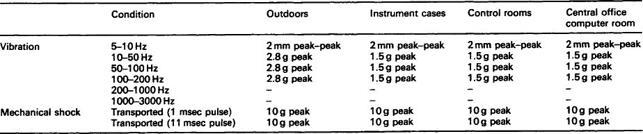
8.2.1.1.1: On or near the roadside Equipment located on or near the roadside needs to be capable of withstanding vibrations and shocks as shown overleaf:
Table 8.1
Minimum requirements (on or near the roadside)

à = peak amplitude (elongation)
*Where A* = peak amplitude (elongation)
As a minimum requirement equipment should be capable of withstanding shocks as shown below:
Table 8.2
| Peak acceleration | A = 100 g |
| Duration of shock | D = 6 ms |
| Form | Semi-sinusoidal |
| Permissible velocity | m/s |
Note: Tests to determine equipment resistance to shocks are detailed in IEC 68.2.27.
Equipment should also be capable of withstanding long-term exposure to shocks as shown below:
8.2.1.1.2: Encapsulated outdoor installations Equipment contained in encapsulated outdoor installations should be capable of withstanding vibrations and shocks as shown below:

8.2.1.1.3: Closed rooms Equipment located in closed room installations should be capable of withstanding self-induced vibrations as shown below:
8.2.1.1.4: Trainborne equipment The vibrations (accelerations and frequencies) to which trainborne equipment is exposed depend upon the equipment location within the vehicle. Pending the progress made by CENELEC Working Groups on an environmental definition based on random vibration, the variation is conventionally considered to be of sine wave form.
Table 8.6 (see next page) provides equivalent sinusoidal maximum conditions to be expected with equipment and should be taken into consideration.
Table 8.6
Equivalent sinusoidal maximum conditions

22–33 Hz Displacement amplitude 1 mm
32–100 Hz Acceleration amplitude 40 m/s2
*Frequencies above 22 Hz use the following values:
8.2.1.1.5: Tractive units and other vehicles Equipment installed in tractive units and other vehicles should be capable of withstanding vibrations and shocks as shown below:

8.2.1.1.6: Other locations Equipment installed in all other locations should be capable of withstanding vibrations and shocks as shown in Tables 8.8 and 8.9.

8.2.1.1.7: Transportation Whilst being transported, equipment will sustain, in its cabinet, mechanical shocks depending on transport conditions. The equipment, in its packaging, shall comply with the tests described in the IEC 68 series.
In many contracts, the following requirements may be stipulated:
• equipment shall be capable of withstanding without deterioration or malfunction all mechanical stresses that occur in service;
• equipment shall be designed to withstand the following stationary/non-stationary vibration (sinusoidal and random) and shock stresses.
The specifier will then include suitable classifications from the IEC 721 series as appropriate to the device being specified, e.g. axle mounted sensor – 5M3.
8.2.1.1.8: Random vibration Equipment should be capable of withstanding random vibration with a power spectral density as shown in Figure 8.4.

8.2.2 Tests
8.2.2.1 Production configuration
All proposed candidate equipment should be tested in their production configuration without the use of any additional external devices that have been added expressly for the purpose of passing mechanical testing, particularly shock and vibration.
Note: If the equipment has been specifically designed to be used with anti-vibration mounts, these mountings should be incorporated in the test.
8.2.2.2 Procuring specification
When tested, the sample shall perform as stipulated in the procuring specification and over the designated vibration, shock and acceleration ranges.
8.2.2.3 Test methods
Test methods for determining the suitability of a specimen shall include:
| IEC 68.2.27 | Environmental testing procedures – Test Ea and guidance: Shock |
| IEC 68.2.29 | Environmental testing procedures – Test Eb and guidance: Bump |
| IEC 68.2.31 | Environmental testing procedures – Test Ec: Drop and topple (primarily for equipment type specimens) |
| IEC 68.2.32 | Environmental testing procedures – Test Ed: Freefall |
| IEC 68.2.35 | Environmental testing procedures – Test Fda: Random vibration wide band – Reproducibility high |
| IEC 68.2.36 | Environmental testing procedures – Test Fdb: Random vibration wide band – Reproducibility medium |
| IEC 68.2.37 | Environmental testing procedures – Test Fdc: Random vibration wide band – Reproducibility low |
| IEC 68.2.50 | Environmental testing procedures – Test Z/Afc: Combined cold vibration (sinusoidal) tests for both heat dissipating and non-heat dissipating specimens |
| IEC 68.2.51 | Environmental testing procedures – Test Z/BFc: Combined dry heat vibration (sinusoidal) tests for both heat dissipating and non-heat dissipating specimens |
| IEC 68.2.55 | Environmental testing procedures – Test Ee and guidance: Bounce |
| IEC 68.2.57 | Environmental testing procedures – Test Ff: Vibration – Time-history method IEC 68.2.59 Environmental testing procedures – Test Fe: Vibration – Sine-beat method |
| IEC 68.2.6 | Environmental testing procedures – Test Fc and guidance: Vibration (sinusoidal) |
| IEC 68.2.7 | Environmental testing procedures – Test Ga and guidance: Acceleration, steady state |


8.4 Tests
This section details some of the test standards which may be applied to equipment and contains:
• details of the most used environmental tests that a purchaser will normally require a manufacturer to adhere to;
Note: Full details of each of these recommended tests are contained in the relevant ISO, IEC or other standard. A full list of these standards is supplied in the reference section of this book. Copies of all these standards may be obtained from any National Standards Organisation.
8.4.1 Shock test (IEC 68.2.27 Test Ea)

8.4.1.1 Introduction
Equipment and particularly components are quite likely to be subjected to shocks that will be at widely varying levels and are frequently complex in nature. The ability of a specimen to withstand infrequent non-repetitive shocks while being transported, used or handled needs therefore to be determined.
For packaged items, the shocks encountered during handling and transportation are often of a simple nature. IEC 68.2.27 has been designed as a check for unpackaged items and is intended to reproduce the effects of non-repetitive shocks likely to be encountered by components and equipment whilst in service and during transportation.
A test to determine the ability of components, equipment and other electrotechnical products to withstand repetitive shocks is provided in IEC 68.2.29 (see paragraph 8.4.2).
8.4.1.2 Purpose of this test
The purpose of this test is to:
• provide a standard procedure for determining the ability of a specimen to withstand specified severities of shock;
• reveal mechanical weakness and/or degradation in specified performance and to use this information to determine whether a specimen is acceptable or not. This test is particularly aimed at specimens which will be subjected to non-repetitive mechanical shock.
8.4.1.3 General conditions
Whereas this test is primarily intended for unpackaged specimens, it may also be used to test the suitability of packaging and to determine their structural integrity and for quality control.
Normally the transportation environment is far more severe than the operational environment and although a specimen has to survive the transportation environment it will also be required to function when it becomes part of the operational environment. Because of this it may be necessary to carry out shock tests under both conditions together with measurements of certain parameters after the ‘transportation environment’ test and functional checks during the ‘operational environment’.
8.4.1.4 Test conditions
IEC 68.2.27 is intended to produce in a specimen the effects of relatively non-repetitive shocks that will probably be encountered by equipment and components in service or whilst being transported.
The standard is written in terms of pulse shapes. The specimen being subjected to a pulse (accelerated against time) whose shape can be either half-sine (which is normally the case), final-peak saw-tooth or trapezoidal (although this is not primarily intended for component type specimens).
The choice of pulse depends on a number of factors, but basically falls into one of the following categories:
Half-sine pulse – most applicable when reproducing the effects of a shock resulting from impact with, or retardation by, a linear rate system (e.g. impact involving a resilient structure).

Final-peak saw-tooth pulse – an asymmetrical triangular pulse with short rise and fall times, which has a more uniform response spectrum than the half-sine or trapezoidal pulse shapes.

Fig. 8.6 Final-peak saw-tooth pulse (reproduced from BS 2011: Part 2.1 Ea:1988 by kind permission of the BSI)

Trapezoidal pulse – a symmetrical trapezoid with short rise and fall times. This pulse produces a higher response over a wider frequency spectrum than the half-sine pulse.
8.4.2 Bump test (IEC 68.2.29 Test Eb)
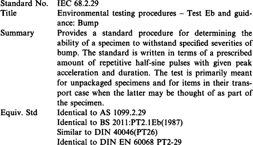

Table 8.13
Examples of pulse shapes and test severities

1One of the basic requirements of the test is to apply three shocks in each of six directions.
2In some components and for most equipment, the internal parts can form more complicated systems than undamped systems. In these cases, excited oscillations in one outer system may cause damage to an inner system by coupled resonant effects.
(reproduced from the equivalent standard BS2011.1.1: 1989 by kind permission of the BSI)
8.4.2.1 Introduction
When being transported and whilst in use, equipment can be subjected to repeated bumps. This test is designed to provide a standard procedure for determining the ability of a specimen to withstand specified severities of bump.
8.4.2.2 Purpose of this test
• to reveal the accumulated damage or degradation caused by repetitive shocks and jolts that are likely to be encountered by components and equipment during transportation or when installed and whilst in use in road and/or rail vehicles as portable equipment, or whilst shipborne;
• primarily intended for unpackaged specimens and for items in their transport case. It may also be used to assess the structural integrity of specimens as a means of quality control.
8.4.2.3 General conditions
This test is basically a robustness test conducted to give a measure of confidence. It may also be used for establishing the satisfactory design of a specimen in as far as its structural integrity is concerned and as a means of quality control. It is not intended to simulate precisely the real environment.
Repetitive bumping during transportation is mainly due to the discontinuities of the medium (e.g. road) and is of moderate intensity. For impacts of a non-repetitive nature, the test described in IEC 68.2.27 (see Section 8.4.1) should be used.
8.4.2.4 Test conditions
IEC 68.2.29 describes a test that subjects a specimen to repetitive shocks (or jolts) of a standard pulse shape with a specified peak acceleration and duration. The severity of the test depends on the specimen under test and the designated number of bumps applied in each direction in three mutually perpendicular axes.
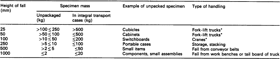
Table 8.14 lists severities which are not mandatory but which are typical of the various applications. As IEC point out, it should be remembered that there will be instances where the real severities differ from those shown in this table.
Table 8.14
Examples of severities typically employed for various applications

It is recommended that the test severities of 250 and 400 m/s2 should only be specified for specimens with a nominal mass of less than 100 kg. For heavier specimens the 100 m/s2 severity is generally more appropriate.
(reproduced from the equivalent standard BS 2011.2.1:1987 by kind permission of the BSI)
8.4.3 Drop and topple tests (IEC 68.2.31 Test Ec)

8.4.3.1 Introduction
During transportation and whilst in use, equipment is quite likely to be roughly handled or subjected to some hard knocks and jolts. This test provides a standard procedure for determining the ability of a specimen to withstand specified severities of drops, topples or pushovers.
8.4.3.3 General conditions
The test should only be specified for equipment that is likely to receive such rough handling (e.g. those that are small to medium in size and mass) and should be applied only to those faces and corners where there is a risk of such treatment being encountered.
This test is primarily intended for specimens out of their packing and is not applicable to equipment forming an integral part of a permanent installation or to specimens which are large enough to make them stable while being handled.
8.4.3.4 Test conditions
IEC 68.2.31 consists of three distinct procedures:

Fig. 8.8 Drop and topple tests – dropping onto a face (reproduced from the equivalent standard BS EN 60068.2.31 by kind permission of the BSI)

Fig. 8.9 Drop and topple tests – dropping onto a corner (reproduced from the equivalent standard BS EN 60068.2.31 by kind permission of the BSI)

The purpose of each of these procedures is basically the same, but they cover different kinds of handling.
8.4.4 Free fall test (IEC 68.2.32 Test Ed)


8.4.4.1 Introduction
During operation and whilst being transported, handled or repaired, unpacked components and equipment are quite likely to be dropped from a work surface or dropped from a means of transport.
8.4.4.2 Purpose of this test
The purpose of this test is to assess the effects of falls that are likely to be received by equipment during rough handling, while being transported or used.
8.4.4.3 General conditions
The test is not suitable for heavy specimens or those with large dimensions (e.g. large power transformers). The test can also be used to demonstrate the minimum degree of robustness, for assessing safety requirements.
8.4.4.4 Test conditions
IEC 68.2.32 specifies two types of procedures:
| Free fall – | this procedure is primarily intended for testing cable connected devices such as small remote control units, and simulates situations (i.e. falls) where apparatus has been dropped frequently onto hard surfaces. The test is normally restricted to two falls from a prescribed attitude onto a specified surface from a specified height. |
| Free fall – | simulating repeated falls. Such repeated falls may occur (repeated) to devices that are normally attached to cables during use. The test consists of a number of repeated falls onto a specified surface from a specified height using a suitable apparatus (e.g. a tumbling, rotating barrel). |
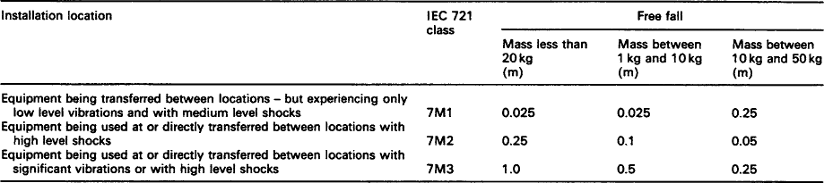
The severity of these tests varies according to the specimen being tested and can be chosen from Table 8.15.
Table 8.15
Examples of test severities typically employed
The total number of falls can be selected from 50, 100, 200, 500 or 1000.
*This is intended to simulate the impact when lowered to the loading level by a fork-lift truck or crane, not dropping from the platform of the truck or sling of the crane.

8.4.5 Random vibration tests (IEC 68.2.34/35/36/37 Tests Fd, Fda, Fdb and Fdc)
These tests are applicable to components and equipment which may be subjected to conditions involving vibration of a stochastic (i.e. random) nature. The purpose of the tests is to determine the resulting degree of mechanical weakness and/or degradation in specified performance that result and to see if the specimen can continue to meet the required specification.
Three possible degrees of reproducibility are specified namely, high (IEC 68.2.35), medium (IEC 68.2.36) and low (IEC 68.2.37).
8.4.5.2 Purpose of these tests
The purpose of these tests is to augment the existing sinusoidal vibration test provided in IEC 68.2.6 (see paragraph 8.4.11) as a step nearer to the type of vibration likely to exist in the real environment and to produce effects in the specimen more closely related to those actually occurring in service.
8.4.5.3 General conditions
It is essential that if random vibration testing is to achieve the degree of realism that justifies its introduction, engineering judgement must be allowed in its application.
In these standards two terms are referred to frequently. For clarification:
8.4.5.4 Test conditions
There are three types of test (IEC 68.2.35/36/37, relating to ‘high’, ‘medium’ or ‘low’ reproducibility) which are designed to determine mechanical weakness, degradation and/or changes in performance of specimens when subjected to conditions involving vibration of a random (stochastic) nature. A fourth standard (IEC 68.2.34) provides guidance in the use and applicability of these tests.
The specimens are vibrated in three mutually perpendicular axes in turn, these axes being chosen to ensure that faults are most likely to be revealed. The severity of the test is defined by the combination of frequency range, Acceleration Spectral Density (ASD) level and duration of conditioning.
8.4.6 Combined cold vibration (sinusoidal) test (IEC 68.2.50 Test Z/AFc)

8.4.6.1 Introduction
During the transportation or storage of heat dissipating and non-heat dissipating equipment they may occasionally be subjected to a combination of low temperature combined with (sinusoidal) vibration.
8.4.6.2 Purpose of this test
The purpose of this test is to determine the suitability of heat dissipating and non-heat dissipating components, equipment or other articles for use, storage and transportation under conditions of low temperature combined with (sinusoidal) vibration.
8.4.6.3 General conditions
The temperature conditions for testing heat dissipating specimens are intended to subject the specimen to thermal stresses in a manner equivalent to those found in free air conditions.
For packaged items, the shocks encountered during handling and transportation are often of a simple nature.
The procedures are limited to the case of specimens which reach temperature stability during exposure to low temperature conditions.
This standard calls for the use of procedures that may be injurious to health if adequate precautions are not taken.
8.4.6.4 Test conditions
IEC 68.2.50 is basically a combination of IEC 68.2.6 (Vibration) (see paragraph 8.4.11) and IEC 68.2.1 (Cold) (see paragraph 2.4.1). The procedure is limited to the case of specimens that reach temperature stability during exposure to low temperature conditions.
Unless these tests have been performed (and the results recorded) a vibration test under laboratory temperature conditions is first performed and the specimen is then subjected to the low temperature until temperature stability has been reached, after which it is subjected to the combination of vibration and low temperature.
Test profiles are shown in the specification and the vibration environment may be a combination of one or more of the following:
8.4.6.5 Other standards
| IEC 68.2.51 | Environmental testing procedures – Test Z/BFc: Combined dry heat/vibration (sinusoidal) tests for both heat dissipating and non-heat dissipating specimens |
| IEC 68.2.53 | Environmental testing procedures – Guidance to Tests Z/AFc and Z/BFc: Combined temperature (cold and dry heat) and vibration (sinusoidal) tests |
8.4.7 Combined dry heat vibration (sinusoidal) test (IEC 68.2.51 Test Z/BFc)

8.4.7.1 Introduction
During the transportation or storage of heat dissipating and non-heat dissipating equipment they may occasionally be subjected to a combination of high temperature combined with (sinusoidal) vibration.
8.4.7.2 Purpose of this test
The purpose of this test is to determine the suitability of heat dissipating and non-heat dissipating equipment under conditions of high temperature combined with (sinusoidal) vibration.
8.4.7.3 General conditions
The temperature conditions for testing heat dissipating specimens are intended to subject the specimen to thermal stresses in a manner equivalent to that found in free air conditions.
IEC 68.2.53 provides guidance on the application of the combined tests.
8.4.7.4 Test conditions
IEC 68.2.51 (Combined dry heat vibration (sinusoidal) test) is basically a combination of IEC 68.2.6 (Vibration) (see paragraph 8.4.11) and IEC 68.2.2 (Dry heat) (see paragraph 2.4.2).
The procedure is limited to the case of specimens that reach temperature stability during exposure to high temperature conditions.
8.4.8 Bounce test (IEC 68.2.55 Test Ee)

8.4.8.1 Introduction
When equipment is carried as loose cargo whilst being transported on load carrying vehicles it is often subjected to severe and repetitive shock from impacting, rebounding and scuffing on the floor of the transporting vehicle or from colliding with the walls of the vehicle or other cargo. Even when tied to the vehicle platform, equipment can be subject to shock if the constraint allows freedom of movement.
The bounce test fulfils a similar function to the bump test of IEC 68.2.29 (see paragraph 8.4.2) except that it more closely simulates the stress resulting from impact and shock to which the specimen would be subjected when carried loose in a vehicle.
8.4.8.2 Purpose of this test
The purpose of this test is to provide a standard procedure to determine the suitability of equipment that has to be transported on a load carrying vehicle when it is either not fastened down or when it has some degree of freedom, and can, therefore, be subjected to dynamic stresses resulting from random shock conditions.
8.4.8.3 General conditions
The shock test may also be used for assessing the satisfactory design of a specimen as far as its structural integrity is concerned.
The test is primarily intended for specimens prepared for transportation, including specimens in their transit case when the latter may be considered as part of the specimen itself.
When items are stacked in a vehicle, there can be significant differences between the environments experienced by the top and bottom layers. It is the transport case of a specimen that is most vulnerable when it is in the bottom layer; while in the top layer, it is its contents.
8.4.8.4 Test conditions
IEC 68.2.55 tests the ability of a specimen to withstand specific severities of bounce.
Whenever possible the test severity applied to the specimen should be related to the operational environment to which the specimen will be subjected during transportation.
Two methods of carrying out the bounce test are given in the standard:
• Method A – this provides a circular motion of amplitude and speed sufficient to produce an acceleration more than 1 gnin the vertical plane. The vertical motion induces bounce and the horizontal motion induces occasional impact with the platform rails.
• Method B – this is based on a non-synchronous platform motion in which two drive points are driven at different speeds which results in a motion that progressively changes from linear vertical to pitching. The vertical motion induces bouncing; the pitching motion impacts with the barrier rails.
Both methods are considered equally effective in simulating the transportation environment.
8.4.9 Vibration test – time-history method (IEC 68.2.57 Tests Ff)

8.4.9.1 Introduction
Equipment whilst being transported or whilst in service may be subjected to short-duration, random type, dynamic forces (e.g. stresses induced in equipment as a result of earthquakes, explosions and some phases of transportation). IEC 68.2.57 provides a standard procedure for determining by the time-history method the ability of a specimen to withstand specified severities of transient vibration.
8.4.9.2 Purpose of this test
• to determine mechanical weakness and/or degradation in specified performance and to use this information, in conjunction with the relevant specification, to decide whether a specimen is acceptable or not;
• to demonstrate the mechanical robustness of specimens and/or to study their dynamic behaviour.
8.4.9.3 General conditions
Many recognised testing procedures exist for demonstrating the ability of specimens to withstand various types of vibrational forces (see previous sections). These procedures range from the simple continuous sinusoid to complex highly specialised time-history methods, each being best suited for particular circumstances or requirements, or for representing a particular vibration environment.
The time-history method becomes important for:
• applications where the vibration environment is to be reproduced as closely as possible;
• applications where little is known about the spectrum, or there is great difficulty in determining critical aspects about the specimen (e.g. critical frequencies, etc.).
Compared with other methods, the time-history method avoids a tendency to overtest because it closely represents the real environment.
The use of a time-history allows a single test wave to envelope a broad response spectrum. A typical time-history is shown in Figure 8.11, whilst Figure 8.12 shows a typical logarithmic plot of a required response spectrum.

Fig. 8.11 Typical time-history (reproduced from the equivalent standard BS EN 60068.2.57 by kind permission of the BSI)

Fig. 8.12 Typical logarithmic plot of a required response spectrum (reproduced from the equivalent standard BS EN 60068.2.57 by kind permission of the BSI)
Natural time-history is the recording, as a function of time, of the acceleration, velocity or displacement resulting from a given event. It should be noted that time-history requires the test laboratory to utilise sophisticated and accurate instrumentation, as well as digital computer equipment for control and analysis.
8.4.9.4 Test conditions
IEC 68.2.57 describes a method for determining the mechanical weakness and/or degradation in specified performance and to use this information, in conjunction with the relevant specification, to decide whether a specimen is acceptable or not. It may also be used, in some cases, to demonstrate the mechanical robustness of specimens and/or to study their dynamic behaviour.
During the test the specimen is subjected to either a natural time-history or a synthesised time-history generated from frequencies included within the specified range and with characteristics simulating the effects of the dynamic forces.
A time-history may be obtained from:
The test severity is defined by a combination of frequency range, required response spectrum, number and duration of time-histories and (where applicable) number of high stress response cycles.
Procedures are described for conducting the test, the choice of test severity, frequency range, required response spectrum, number and duration of time-histories, the number of high stress response cycles and for measurement of the vibration at given points.
8.4.10 Vibration test – sine-beat method (IEC 68.2.59 Test Fe)

8.4.10.1 Introduction
Whilst in service, equipment can be subjected to pulsating or oscillating forces for short durations (e.g. caused by seismic explosive phenomena or by vibration in machinery). IEC 68.2.59 provides a standard procedure for determining the ability of components, equipment and other electrotechnical products to withstand specified severities of transient vibration.
8.4.10.2 Purpose of this test
The purpose of this test is to provide a standard procedure for determining, by the sine-beat method, the ability of a specimen to withstand specified severities of transient vibration.
8.4.10.3 General conditions
In vibration testing, the usual approach is to conduct a vibration response investigation to search for the critical frequencies of the specimen in the required frequency range. Some form of endurance test is then undertaken which often consists of vibrating a specimen for prescribed times at each of these critical frequencies.
The vibration response investigation is normally carried out using single-axis sinusoidal excitation with a single sweep cycle over the required frequency range. The amplitude of vibration during this investigation should not be so large as to produce effects comparable to those of the endurance test itself and should be at a sufficiently low sweep rate to determine the critical frequencies. A change in frequency may indicate that some fatigue has occurred and the specimen may therefore be unsuitable for the operational environment.
The sine-beat method is suitable for testing equipment that is subjected in service to pulsating or oscillating forces of short durations that are not accurately defined. It is particularly suitable for testing equipment that is to be mounted in structures that may then be subjected in service to random or multi-frequency excitations.
The reproduction of the effects of low cycle, high stress fatigue that could be produced by vibration (e.g. produced by earthquakes, explosions) requires that the specific environment be simulated as accurately as possible.
8.4.10.4 Test conditions
IEC 68.2.59 provides a standard procedure for determining the ability of equipment to withstand specified severities of transient vibration.
Procedures are described for conducting the test (e.g. exciting the specimen at fixed frequencies with a preset number of sine beats) and for the measurement of the vibration at given points.
The requirements for the vibration motion and for the choice of severities (including frequency range, test levels, sine-beat cycles and number of sine beats) are also detailed.
Pauses are deliberately inserted between the individual sine beats to allow decay of the free response of the specimen.
8.4.11 Vibration (sinusoidal) tests (IEC 68.2.6 Test Fc)

8.4.11.1 Introduction
Equipment, during transportation or whilst in service, may be subjected to prolonged conditions involving vibration of a harmonic pattern, generated primarily by rotating, pulsating or oscillating forces, similar to those caused by machinery and seismic phenomena. IEC 68.2.6 provides a standard procedure for determining the ability of components, equipment and other articles to withstand specified severities of sinusoidal vibration.
8.4.11.2 Purpose of this test
The purpose of this test is to determine mechanical weakness and/or degradation in specified performance, and to use this information, together with the relevant specification, to decide whether or not an item of equipment or component is acceptable.
8.4.11.3 General conditions
In vibration testing the usual approach is to search for the resonances and then to undertake an endurance test in which a specimen is vibrated at resonant frequencies for a prescribed time.
The problem with this sort of test is that it is extremely difficult to differentiate between resonances which are liable to cause failure in service and those likely to cause trouble. Endurance by sweeping, which the test also includes, reduces these difficulties and avoids the necessity of defining significant and damaging resonances.
IEC 68.2.6 is also used to determine critical frequencies at which the specimen malfunctions (or its performance deteriorates) and can be used to determine when mechanical resonances and other response effects (e.g. chatter) occur. Sometimes this test may be used to detect the structural integrity of specimens and/or study their dynamic behaviour.
The main part of this standard deals primarily with the methods of controlling the test at specified points and details the test procedures. The requirements for vibration motion, choice of severities – including frequency ranges, amplitudes and endurance times – are also specified.
8.4.11.4 Test conditions
IEC 68.2.6 describes a method for detecting the effect on an item of equipment in terms of mechanical weakness and/or degradation in specified performance, when that equipment (during transportation or while in service) has been subjected to vibration of a harmonic pattern.
For the purposes of this test, the specimen is subjected to sinusoidal vibration whose vibration severity is determined by the combination of vibration, frequency range amplitude and duration of endurance.
The frequency changes exponentially with time and varies at a continuous rate of ±10%, i.e. one octave per minute.
The maximum vibration amplitude (displacement or acceleration, or both) at the check points, in any axis perpendicular to the specified axis, is not normally allowed to exceed 50% of the specified amplitude for frequencies up to 500 Hz, or 100% for frequencies greater than 500 Hz.
The frequency range recommended for this test is provided in a series of tables (see the example in Table 8.17) and covers the range from 0.1 Hz to 5000 Hz.
Table 8.17
Examples of test severities typically employed for various applications

(taken from the equivalent standard EN 60068 PT2-6 by kind permission of the BSI)
The duration of the test depends on whether the test is intended to simply show the ability of a specimen to survive and/or operate at the appropriate amplitudes or whether the ability of an item of equipment to withstand the cumulative effects of vibration is to be shown.
8.4.11.5 Other standards
| IEC 68.1 | Environmental testing procedures – General and guidance |
| IEC 68.2.34 | Environmental testing procedures – Test Fd: Random vibration wide band – General requirements |
| IEC 68.2.35 | Environmental testing procedures – Test Fda: Random vibration wide band – Reproducibility high |
| IEC 68.2.36 | Environmental testing procedures – Test Fdb: Random vibration wide band – Reproducibility medium |
| IEC 68.2.37 | Environmental testing procedures – Test Fdc: Random vibration wide band – Reproducibility low |
| IEC 68.2.47 | Environmental testing procedures – Mounting of components, equipment and other articles for dynamic tests including Shock (Ea), Bump (Eb), Vibration (Fc and Fd) and Steady state acceleration (Ga) and guidance |
| IEC 68.2.64 | Environmental testing procedures – Vibration, broadband random (digital control) and guidance |
| IEC 721.1 | Classification of environmental conditions – Environmental parameters and their severities |
| ISO 2041 | Vibration and shock – Vocabulary |
8.4.12 Impact, pendulum hammer test (IEC 68.2.62 Test Ef)

8.4.12.1 Introduction
Electrical accessories such as switches, lampholders and wall mounted power outlets may, during operation, transportation or storage, be subjected to damage by impacting with foreign bodies. IEC 68.2.62 evaluates a component’s capability of surviving these shocks.
8.4.12.2 Purpose of this test
The purpose of this test is to provide a standard method of test for determining the ability of an electrotechnical product to withstand specified severities of impact. It is mainly used to demonstrate an acceptable level of mechanical robustness when assessing the ‘safety’ of the product.
8.4.12.3 Test conditions
IEC 68.2.62 is primarily intended for the testing of specimens with electrical accessories, such as switches and lampholders. It consists of the application to the specimen of a prescribed number of horizontal impacts, each defined by the height of fall and mass of the pendulum hammer.
The test apparatus consists basically of a 1 m long pendulum comprising a rigid tube and a mass that strikes the specimen. This striking element, which is rigidly fixed to one end of the tube, comprises a steel body with a polyamide insert having a hemispherical face of 10 mm radius and a combined mass of 150 g ± 1 g.
The design of the apparatus is such that a force between 1.9 N and 2.0 N has to be applied to the striking element to maintain the tubular arm of the pendulum in a horizontal position.
8.4.12.4 Other standards
| IEC 68.1 | Environmental testing procedures – General and guidance |
| IEC 68.2 | Environmental testing procedures – Tests |
| IEC 68.2.47 | Environmental testing procedures – Mounting of components, equipment and other articles for dynamic tests including Shock (Ea), Bump (Eb), Vibration (Fc and Fd) and Steady state acceleration (Ga) and guidance |
| IEC 68.2.63 | Environmental testing procedures – Impact, spring hammer |
| IEC 1052 | Steels for general engineering purposes |
| IEC 1098 | Veneer plywood for general use – General requirements |
| IEC 721 | Classification of environmental conditions |
| IEC 817 | Spring operated impact-test apparatus and its calibration |
| ISO 2039.2 | Plastics – determination of hardness – Rockwell hardness |
| ISO 2041 | Vibration and shock – vocabulary |
8.4.13 Acceleration, steady state test (IEC 68.2.7 Test Ga)

8.4.13.1 Introduction
Equipment components and other electrotechnical products installed on moving bodies will normally be subjected to forces caused by steady accelerations. IEC 68.2.7 provides a standard procedure to prove the structural suitability of equipment.
8.4.13.2 Purpose of this test
The purpose of this test is to prove the structural suitability and the satisfactory performance of equipment, components and other electrotechnical products when subjected to forces produced by steady state environments (other than gravity) such as occur in moving vehicles.
8.4.13.3 General conditions
In many applications, the forces on a moving body giving rise to acceleration are invariably complex. These forces can be considered, at any one instant, to be a single force which can be described in direction by its angular position relative to the three main axes of the moving body. For design purposes, the maximum acceleration levels for a particular manoeuvre of the moving body need to be specified with respect to each major axis of the moving body.
This test may also be used for establishing the satisfactory design and manufacture of a component, insofar as its structural integrity is concerned. Certain components, notably from the semiconductor industry, are checked for structural integrity (i.e. sound mechanical assembly) by the application of a very high acceleration. The tests are used as a simple means of applying a high stress to reveal possible constructional weaknesses.
8.4.13.4 Test conditions
IEC 68.2.7 describes a test to prove the structural suitability and the satisfactory performance of equipment, components and other electrotechnical products when subjected to forces produced by steady state environments.
Table 8.18 is a list of typical test severities.
Table 8.18
Examples of test severities typically employed for various applications
| Acceleration, a (m/s2) | Application |
| 30 < a < 100 | Proof level for specimens to be mounted in aircraft |
| 50 < a < 200 | Structural or ultimate level for specimens to be mounted in aircraft and for crash safety of mountings |
| 100 < a < 1000 | General testing for aerospace applications |
| a > 5000 | Structural integrity tests for semiconductor devices, integrated circuits, etc. |