
Chapter 5: Creating a 2D Adventure Game
In this chapter, we will start an entirely new project: a 2D adventure game where the player controls an alien character and explores and navigates a dangerous world, complete with a quest to collect a gem. Platform games have been hugely popular since their inception in the 1980s with the first platforming game Space Panic. Since then, the genre has grown drastically to include the likes of Super Mario, Mega Man, Crash Bandicoot, and Limbo.
This project will build on the ideas we introduced in previous chapters but will also introduce new techniques, such as complex collisions, 2D physics, singletons, and more. Learning these techniques will empower you to create your own 2D games. In this chapter alone, we will cover the following topics:
- Configuring the game view by adjusting the camera's vertical size to ensure our sprites are shown at the correct size
- Creating an environment including a 2D level with a background and foreground
- Adding post-processing effects to improve the look of our game
- Creating a 2D player consisting of several GameObjects
- Moving the player using 2D physics and collision detection
- Optimizing rendering using Unity's Sprite Packer
Let's get started!
Technical requirements
This chapter assumes that you have not only completed the projects from the previous chapters but also have a good, basic knowledge of C# scripting in general, though not necessarily in Unity.
The starting assets can be found in this book's companion files, in the Chapter05/Assets folder. You can start here and follow along with this chapter. The end project can be found in the Chapter05/End folder.
Getting started
Adventure games require the player to use their cunning, dexterity, mental sharpness, and acumen to make progress. Such games feature dangerous obstacles, challenging missions, and character interaction, as opposed to all-out action like many first-person shooter games. Our adventure game will be no exception. The following is a screenshot of the game that we'll be creating:

Figure 5.1 – The 2D adventure game we'll be creating
In this game, the player moves around using the keyboard arrows or W, A, S, and D keys. Furthermore, they can jump with the spacebar and interact with other characters by approaching them. During the game, the player will be tasked with a mission from an NPC character to collect an ancient gem hidden somewhere within the level. The player must then navigate dangerous obstacles in search of the gem before returning to the NPC, completing the game.
To get started, do the following:
- Create a new Unity project using the 2D Project Template. The project creation process was outlined in Chapter 1, Exploring the Fundamentals of Unity.
- Import the Standard Assets Package (once again, this process is outlined in Chapter 1, Exploring the Fundamentals of Unity). This package includes particle effects, character control, and cross-platform input systems that we'll use in our game.
- Next, we'll import the texture assets we'll be using, both for the player character and the environment. The assets to import are included in this book's companion files, in the the Chapter05/Assets folder. From here, select all the textures and drag and drop them into the Unity Project panel in a designated Textures folder (create one if you haven't already!). This will import all the relevant textures into the active project, as shown in the following screenshot:

Figure 5.2 – Importing texture assets into the active project
Tip
Remember that you can always use the Thumbnail Size Slider (at the bottom-right corner of the Project panel) to adjust the size of thumbnail previews in order to get an easier view of your texture assets.
Now that we've created the project using the 2D template, the textures should be imported as sprites rather than as textures for a 3D model. To confirm this, do the following:
- Select all the imported textures.
- From the Inspector, make sure that the Texture Type field is set to Sprite (2D and UI).
- If enabled, remove the checkmark from the Generate Mip Maps box.
- Lastly, if you made any changes, click on the Apply button to save your changes:

Figure 5.3 – Configuring the imported textures
With the changes applied, Unity flags the assets as having a 2D usage internally. This allows transparent backgrounds to be used where applicable (such as for PNG sprites) and also has important performance implications for graphics rendering, as we'll see later in this chapter. Before that, we'll configure the game view in preparation for creating the environment and player objects.
Configuring the game view
Now that we've imported all the essential textures for the project, let's configure the Game panel resolution and game camera. We should configure the game view correctly at the beginning of the project as it controls how we and, consequently, the end user sees the game. This, believe it or not, will help us when we come to creating the environment. We'll start with the Game panel's resolution, before moving on to configuring the game's camera.
Changing the Game panel's resolution
We'll use a resolution of 1024 x 600 for our game, which works well across many devices. To do this, follow these steps:
- Click on the Free Aspect button from the Game tab on the toolbar.
- Select 1024 x 600 from the drop-down menu.
If the required resolution is not available, then do the following:
- Click on the + button from the bottom of the list.
- Enter a custom name in the Name field.
- Select Fixed Resolution from the Type dropdown.
- Type your resolution dimensions into the Width and Height fields.
- Click on OK.
Your target resolution should then be added as a selectable option from the Game tab, as shown in the following screenshot:

Figure 5.4 – Creating a custom resolution
The resolution for the Game panel is not necessarily the resolution of the final game. You can set the resolution of the compiled game using the Project Settings panel. For more details, see Chapter 2, Creating a Collection Game.
With the correct game resolution, we can move on to configuring the game camera in preparation for creating our first 2D level.
Adjusting the scene camera's size
In this section, we'll configure the scene camera for use in a 2D game so that our textures, when added as sprites, will display onscreen at a 1:1 ratio, Texel (texture pixel) for pixel. The camera will already be configured with an orthographic projection because we used the 2D template. The alternative (perspective projection) is often used with 3D games and would be the default configuration if we had selected any of the 3D project templates.
Important Note
Orthographic projection removes any sense of perspective and is often used for 2D games. For more information on the perspective and orthographic projections, see Chapter 3, Creating a Space Shooter.
In our game, we want the sprites to appear onscreen exactly the same size as they are in the texture files. To achieve this, we need to adjust the Size field of the Main Camera object in the Inspector window. The Size field defines the viewing volume of the camera. A larger size results in a larger viewing volume, making all visible objects appear smaller, and vice versa.
The formula we'll use for this field to ensure that the sprites are the same size as they appear in their image files is Screen Height / 2 / Pixel to World. The pixel to world ratio details how many pixels in the texture will be mapped to 1 unit in the world. A Unity unit is an arbitrary length measurement, usually interpreted as equaling a meter. Therefore, 1 unit is equal to 1 meter in our game. This value can be viewed by doing the following:
- Selecting a sprite in the Project panel.
- Inspecting the Pixels Per Unit field in the Inspector window. You can also change the value here.
The sprites in our game are configured with the default value of 100 pixels to units. Now that we know the pixel per unit value, we can use the aforementioned formula to calculate the required camera size:
- We previously set the screen height to 600 so 600 / 2 = 300.
- We know that our pixel to world ratio is set to 100 so 300 / 100 = 3.
We now know the value we should use for the Camera Size field, so let's set it:
- Select Main Camera from the Hierarchy window.
- In the Inspector window, on the Camera component, enter 3 in the Size field.
- To test the camera and scene settings, drag and drop a background texture from the Project panel to the Scene. The background textures are sized at precisely 1024 x 600 to fit the scene's background. Therefore, when added to a scene with a correctly configured camera, the background textures should fill the screen, as shown in the following screenshot:

Figure 5.5 – Testing the camera settings with a texture
Looking good! In the next section, we'll create something interesting for the player to view using our newly configured 2D camera.
Creating an environment
Our adventure game will feature three separate but connected scenes that the player can explore, moving from one scene to the next. The player may travel between scenes by traversing the edge of a scene. Each scene consists primarily of platforms and ledges and, in some cases, obstacles that must be overcome. In terms of graphical assets, each scene is made up from two textures or sprites: the background and foreground. The preceding screenshot shows the background of the first scene, while the following screenshot shows the foreground, which includes a complete layout of all the platforms and ledges that the player must traverse:

Figure 5.6 – Scene foreground
Important Note
These files are included in this book's companion files, in the Chapter05/Assets folder.
Let's create the first level:
- Drag and drop both the background (tex_level01_bck) and foreground (tex_level01_design) sprites from the Project panel into the Scene. Both will be added to the scene as separate sprite objects.
- Position them at the world origin by setting the Position to 0, 0, 0, as shown here:
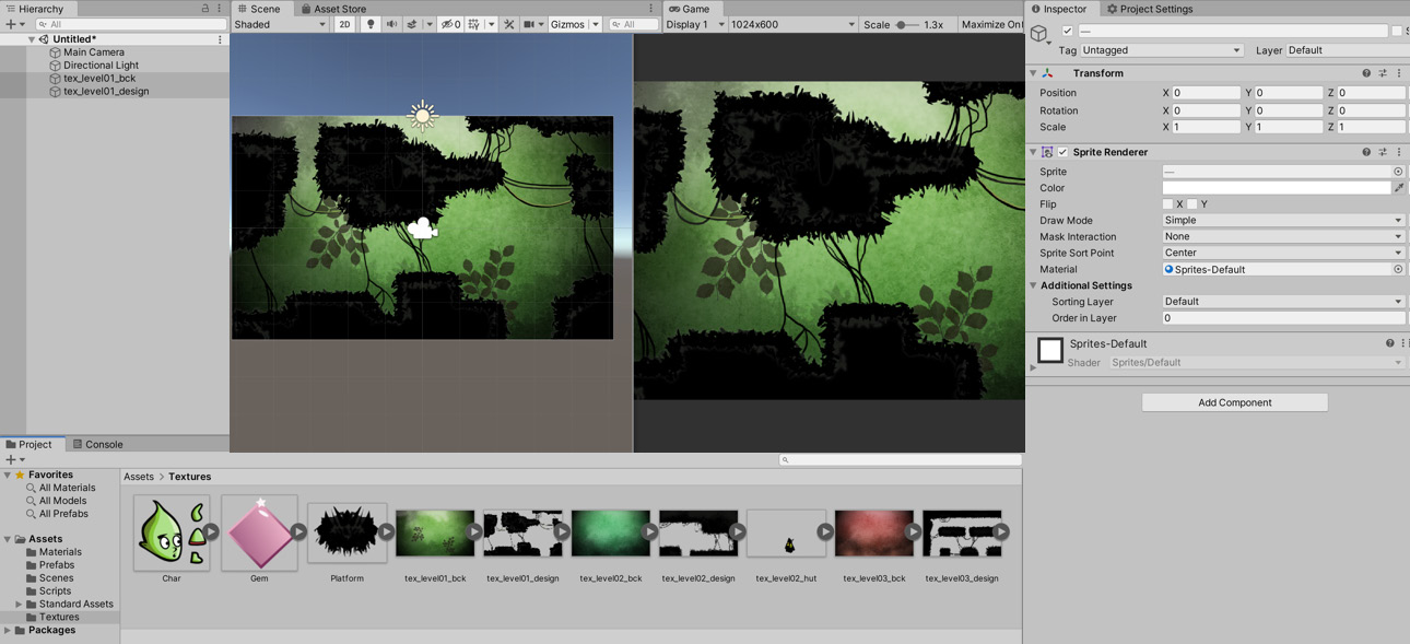
Figure 5.7 – Adding a scene background and foreground
Important Note
If you drag and drop both the background and foreground textures together as one selection from the Project panel to the scene, Unity may ask you to create an Animation when you release your mouse. In such cases, Unity assumes that you want to create an animated sprite in which each selected texture becomes a frame of animation played in a sequence. You don't want to do this; instead, drag and drop each sprite individually.
With both sprites added to the scene at the same world position, the question arises now as to which sprite Unity should display on top, given that both sprites overlap one another. Left as it is right now, there is a conflict and ambiguity about depth order, and we cannot rely on Unity consistently showing the correct sprite on top. We can solve this problem with two methods: one is to move the sprite forward on the Z-axis, closer to the Orthographic camera, while the other is to change its Order setting from the Inspector window. High values for Order result in the sprite appearing atop lower-order sprites. Here, I'll use both methods, and that's fine too!

Figure 5.8 – Ordering sprite layers in a scene
Note, however, that order always takes precedence over position. Objects with a higher order value will always appear on top of objects with lower order values, even if higher-order objects are positioned behind lower-order objects.
Before moving further, let's organize the scene hierarchy to prevent overcomplication and confusion occurring later:
- Select each environment object and name them appropriately. I named the background scene_background and the foreground scene_foreground.
- Create a new, empty GameObject, which will be the parent object of all static (non-movable) objects in the scene, by selecting GameObject | Create Empty from the application menu.
- Rename the object Env (for environment).
- Position the object at the world origin by setting the Position to 0, 0, 0.
- Drag and drop the background and foreground objects onto the newly created GameObject to convert them into child objects.
Important Note
Having an empty parent object like this is a standard method of grouping all related objects easily.
Our game is already looking great. However, by adding post-processing effects, we can further improve the appearance of the game. Let's look at how to do that.
Adding post-processing effects
By switching to the Game tab, we can get an early preview of the level as it will appear to the gamer in terms of mood and emotional resonance. This feeling can be enhanced further by adding some camera post-process effects with the post-processing stack. These refer to pixel-based effects that can be applied to the camera in order to improve the atmosphere for the final, rendered image on a per-frame basis. Let's take a look:
- Import the Post Processing package using the Package Manager by searching for Post-processing Stack.
- Once imported, you can add image effects to the selected camera using a Post-processing Profile. To create a profile, right-click in the Project panel and select Create | Post-processing Profile. This will generate a new asset for saving all post-processing data:
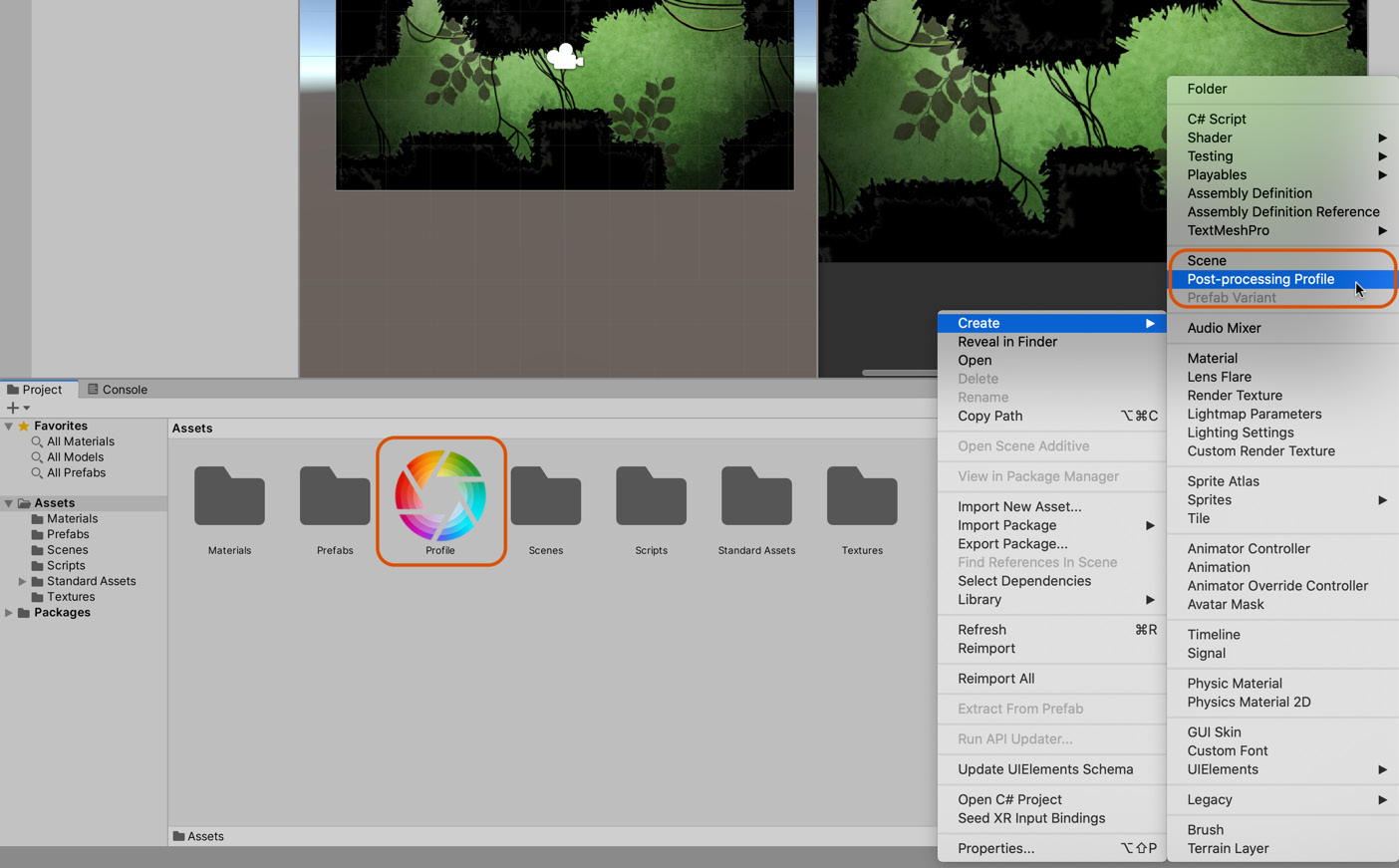
Figure 5.9 – Adding Image Effects to the selected camera
- Next, let's create a new Post-process Volume in the scene to define a volume inside which the effect will apply whenever the camera enters. Select GameObject | 3D Object | Post-process Volume from the main menu to create a new Post-process Volume object in the scene.
- Adjust the Size field of the Box Collider to 13, 8, 1 to enclose the entire scene, as we want the effects to apply throughout the game.
- Drag and drop the Post-processing Profile from the Project panel into the Profile slot of the Post-process Volume component. This associates the profile, and its effects, with the volume:

Figure 5.10 – Defining a Post-process Volume
- You'll need to add a Post-process Layer component to the main camera for the effects to work as intended. To do this, select the camera and choose Component | Rendering | Post-process Layer from the application menu.
- Once added, you'll need to define post-process effects using the profile. Select the Profile asset in the Project panel and choose Add Effect to bring up a menu.
- Using this menu, add both Unity | Bloom and Unity | Grain.
- Configure each using the settings shown in the following screenshot:
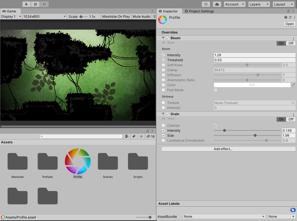
Figure 5.11 – Image Effects applied to the game camera
Good work. The scene so far features a background and foreground taken from texture files with enhanced visual effects by using the Post-processing stack package. This is a great start, but there's still much to do. For instance, while the levels now look the part, if we did have a player, they would fall straight through them as we have no environmental physics. We'll fix this now by adding colliders to the levels and creating a temporary character to test the colliders.
Implementing environmental physics
The main problem with our level, as it stands, is that it lacks interactivity. If we dragged and dropped a player object into the level and pressed play on the toolbar, the player would fall through the floor and walls because Unity doesn't recognize the foreground texture as a solid object. It's just a texture and exists only in appearance and not in substance. In this section, we'll correct this using Physics and Colliders. To get started, we'll create a player object (not the final version but just a temporary White Box version used only for testing purposes). Let's get started:
Generate a capsule object in the scene by navigating to GameObject | 3D Object | Capsule from the application menu.
- Once generated, remove the Capsule Collider from the object by clicking on the three dots icon on the Capsule Collider component in the Inspector window and choosing Remove Component from the menu, as shown here:

Figure 5.12 – Removing the Capsule Collider component
- Set the Z position of the Transform so that it matches the foreground texture (for me, this is -2).
By default, the Capsule is assigned a 3D collider (such as the Capsule Collider), which is useful primarily for 3D physics. However, our game will be in 2D, hence the need to remove the existing collider.
To make the object compatible with 2D physics, add a Circle Collider component:
- Select Component | Physics 2D | Circle Collider 2D from the application menu.
- Use the Offset and Radius settings on the Circle Collider component in the Inspector window to adjust the size and position of the circle to approximate the feet of a player character.
- Next, to make the Circle Collider work with 2D physics, add a RigidBody2D component to the Capsule by selecting Component | Physics 2D | RigidBody 2D from the application menu.
To aid you in positioning the Circle Collider, you can switch the Scene viewport mode to Wireframe and 2D, as shown in the following screenshot:

Figure 5.13 – Adjusting the Circle Collider for the player character
You can confirm that this has worked by previewing the game in Play mode. When you click on the Play icon, the Capsule object should fall down and through the foreground floor under the effect of gravity.
Now, it's time to configure the foreground texture so that it works as a unified whole with physics. Right now, our test player character falls through the floor, and this is not what we want. To fix this, we'll need to also add a collider to the foreground environment. One method to accomplish this is to use Edge Collider 2D. The edge collider lets you draw out a low polygon mesh collider around your ground image manually, approximating the terrain. To get started, follow these steps:
- Select the foreground in the scene.
- Choose Component | Physics 2D | Edge Collider 2D from the application menu to add a collider.
- Position the player above the horizontal line and press Play on the toolbar to see the player character fall downward and treat the horizontal edge as a solid platform:

Figure 5.14 – The Edge Collider is useful to approximate platforms and solid surfaces
By default, adding an Edge Collider 2D appears to have little effect on the selected object or any other objects, except for a single horizontal line drawn across the width of the scene. As with all colliders, it can be seen in the Scene tab when the foreground object is selected and in the Game tab if the Gizmos tool button is enabled.
Of course, our terrain isn't merely a straight-edged surface. Instead, it has elevations, bumps, and platforms. These can be approximated closely with the Edge Collider 2D component using the Collider Edit mode. Let's take a look:
- To access this mode, click on the Edit Collider button in the Inspector window:

Figure 5.15 – The Edit Collider lets you change the shape of an Edge Collider 2D
- With Edit Collider mode active, you can reshape the collider so that it conforms to the terrain. Let's focus on one area, such as the bottom-right-hand side of the terrain. By moving your mouse cursor over the edge points of the Edge Collider (the green line), you can click and drag to reposition them. To approximate the bottom-right island of the terrain, click and drag the rightmost edge point to the right-hand side of the scene, as shown in the following screenshot:

Figure 5.16 – Starting to reshape the Edge Collider to approximate the terrain
- Next, click and drag the left point of the collider so that it matches with the leftmost edge of the right-hand island:
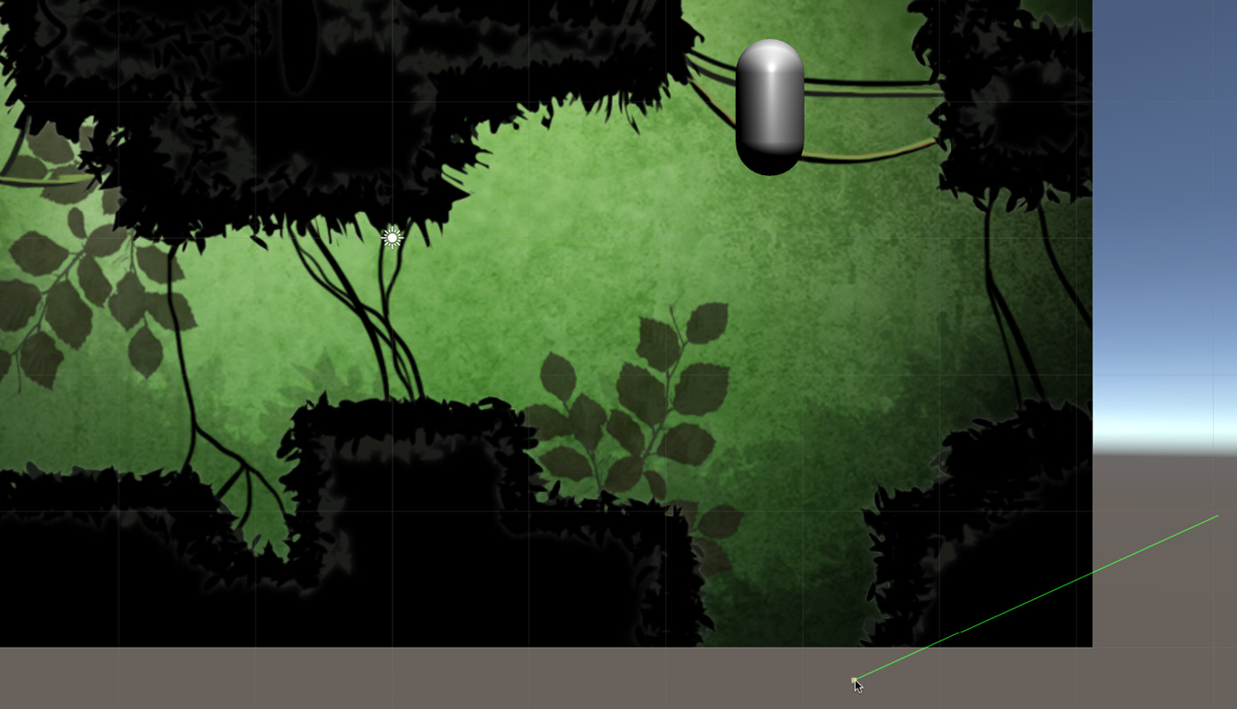
Figure 5.17 – Positioning the leftmost edge of the right-hand island
- Now that the left and right edge points are positioned, add some additional points on the line between them to reshape it so that it conforms to the right-hand island. Move your cursor anywhere on the line, click and drag to insert a new point, and reposition it so that it matches the island. Repeat this process, adding additional points to reshape the line as needed, until it looks similar to what can be seen in the following screenshot:

Figure 5.18 – Shaping the Edge Collider to the rightmost island
- You now have a shaped line that matches the terrain's rightmost island. Having created this, exit Edit Collider mode by once again clicking on the Edit Collider button in the Inspector window.
- To create colliders for the remaining islands of the terrain, add a new Edge Collider to the same object. You can then add any number of Edge Colliders to a single object, and each collider should be used to approximate the topology of an individual, isolated island in the complete terrain. See the following screenshot for the completed island collider:
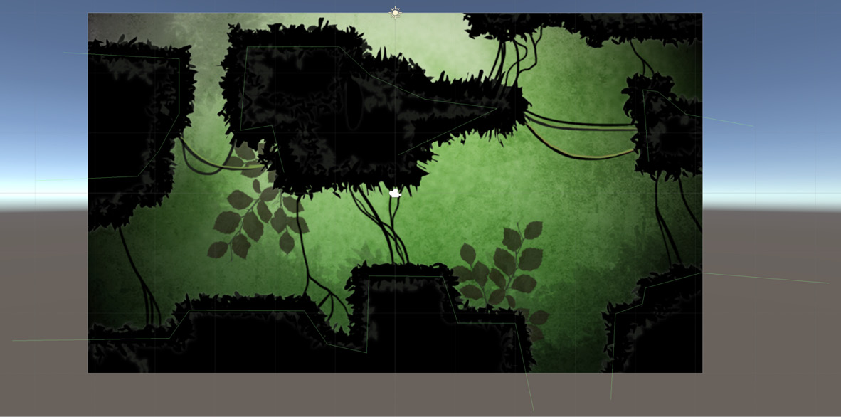
Figure 5.19 – Multiple Edge Colliders on one object can be used to approximate complex terrain
With multiple Edge Collider components being used to approximate the complete terrain for the scene, we can now test play collisions against the Player Capsule object. You'll notice that, this time, the capsule will collide and interact with the ground as opposed to passing through it. This interaction confirms that the terrain has been configured appropriately with the physics system.
Congratulations! In this section, we've created a complete terrain for a single scene using Edge Collider components. This terrain not only fits the screen and appears as intended but acts as a physical obstacle for the player character and other physics-based objects. So far, we've only been using a rough approximation of the player. Now, it's time to expand upon this by implementing the final version of the player character.
Creating a 2D player
The player character is a small, green alien-looking creature that can be controlled and guided by the gamer through a level using many conventional platforming game mechanics, such as walking and jumping. In the previous section, we built a white box (prototype) character to test physical interactions with the environment, but here, we'll develop the player character in more depth. We'll look at the following aspects:
- Using Unity's Sprite Editor to unpack the player sprite sheet, thus creating multiple sprites from one texture.
- Creating the player GameObject. The process of creating a GameObject has been shown several times in this book already, as it's a core concept for any Unity game. However, the player object will be slightly more complex than previous objects, as we need to add different sprites for each limb of the player.
- Adjusting the sorting order of the player's sprites so that they are drawn in the correct order.
- Finally, we'll add the player object to the physics engine so that it can interact with our level.
That's a lot to cover, so let's jump right in with creating the player sprites using the Sprite Editor.
Using the Sprite Editor
The following image illustrates our character texture, which we imported earlier in this chapter, representing all the limbs and parts of the player:

Figure 5.20: Character Sprite Sheet
This player texture is called an Atlas Texture or Sprite Sheet because it contains all the frames or parts of a character in a single texture space. The problem with this texture, as it stands, is that when dragged and dropped from the Project panel into the scene, it'll be added as a single sprite, as shown in the following screenshot:

Figure 5.21: The player sprite texture needs to be divided into separate parts
To divide the character texture into separate parts on a per-limb basis, we'll use the Sprite Editor:
- Select the character texture in the Project panel.
- From the Inspector window, change Sprite Mode from Single to Multiple.
- Click on Apply.
- Click on the Sprite Editor button to open the Sprite Editor tool. This allows you to cut the texture into specific slices:

Figure 5.22 – Specifying a sprite as Multiple
With the Sprite Editor tool, you can separate different parts of a texture into discrete and separate units. One method to achieve this is by drawing a rectangle around each image area that should be separate, and then clicking and dragging your mouse to draw a texture region, as shown in the following screenshot:

Figure 5.23 – Slicing a sprite manually
Although a sprite can be separated manually, as we've just seen, Unity can often cut apart the texture automatically, identifying isolated areas of pixels and saving us time. We'll do that here for the player character:
- Click on the Slice button listed in the top-left corner of the Sprite Editor window.
- From the Slice tool window, ensure that Type is set to Automatic, which means that Unity will auto-detect the location of separate sprites. Pivot can be left as Center, which determines the pivot point for each sprite.
- Set Method to Delete Existing, meaning that any existing sprites or slices in the texture space will be erased and replaced entirely by the newly autogenerated slices, as shown in the following screenshot:
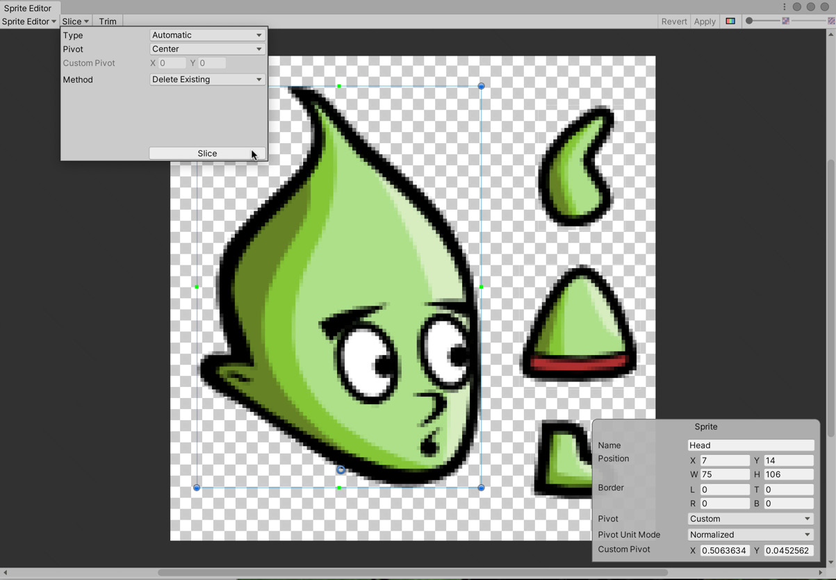
Figure 5.24 – Accessing the Slice tool
- Click on the Slice button to confirm the operation, and the texture will be sliced into separate sprites with a clear border drawn around each sprite.
The texture is now divided into several sprites: head, body, arm, and leg. The final character in-scene will have two arms and two legs, but these will be formed from duplicated sprites. The next step is to set the pivot point for each sprite – the point around which the sprite will rotate. This will be important later to animate the character correctly, as we'll see. Let's start by setting the pivot for the head:
- Select the head sprite in the Sprite Editor window.
- Click and drag the pivot handle (blue circle) to the bottom middle of the head, roughly where the head would connect to the neck, to reposition the sprite's center of rotation. This position makes sense because the head will rotate and hinge from around this point. The exact location is shown in the following screenshot:
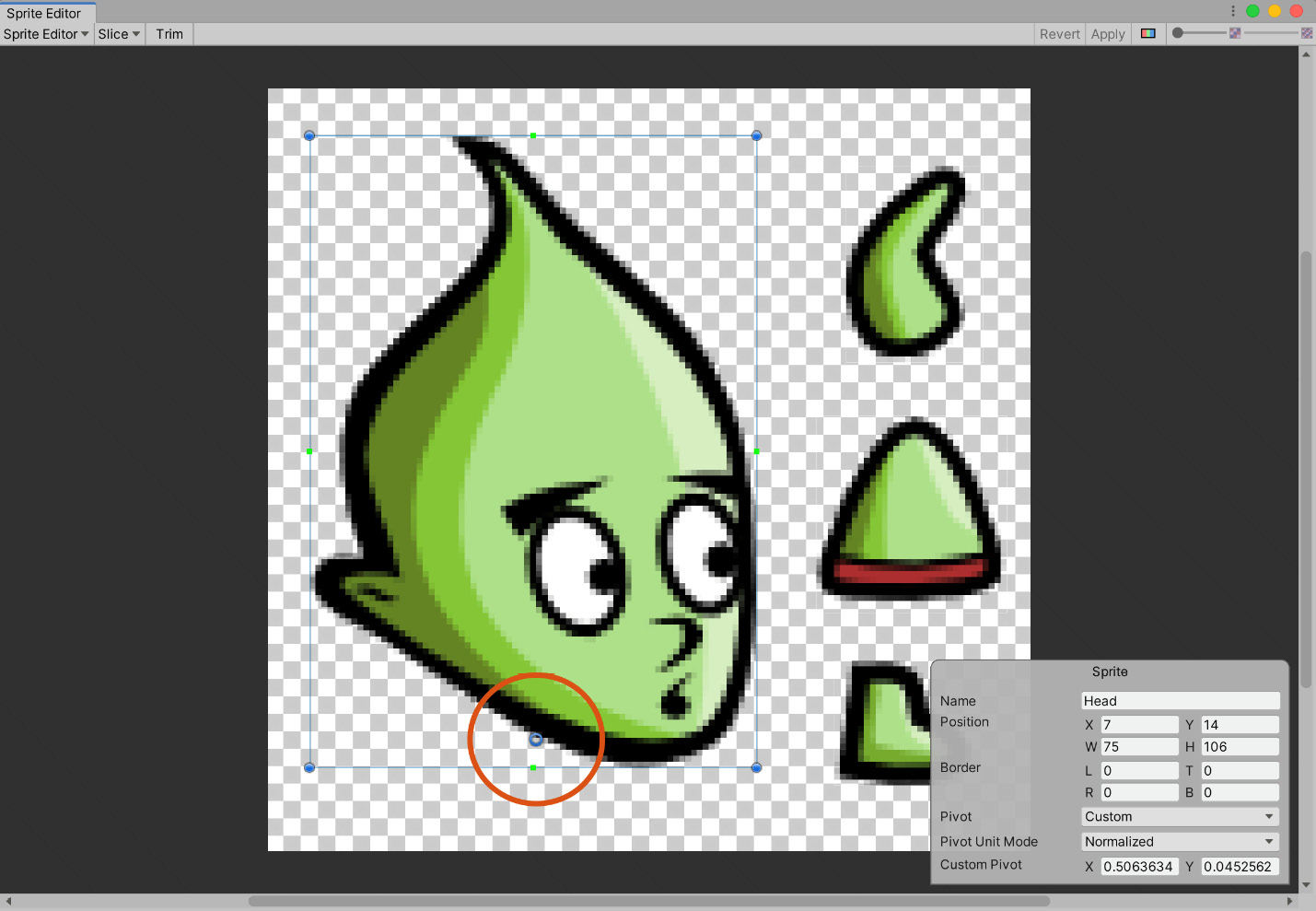
Figure 5.25 – Repositioning the sprite pivot
Important Note
As you move the pivot around, you should see the X and Y values change in the Custom Pivot field in the Sprite Properties dialog, shown in the bottom-right-hand corner of the Sprite Editor window.
- Position the pivot for the arm, which should be at the shoulder joint where the arm connects to a torso.
- Position the leg pivot near the hip where the leg connects to the torso.
- Finally, position the torso itself, whose pivot should be at the hip joint, as shown in the following screenshot:

Figure 5.26 – Positioning the pivot for the torso
- When completed, click on the Apply button to confirm changes and then close the Sprite Editor window.
On returning to the main Unity interface, the appearance of the character texture will have changed in the Project panel. The character texture should now feature a small arrow icon attached to the right-hand side. When you click this, the texture expands to review all the separate sprites in a row, which can be dragged and dropped individually into the scene:

Figure: 5.27 – Previewing character sprites
Now that we've isolated all the player sprite textures, we can start building a game character in the scene.
Creating the player GameObject
As mentioned previously, the player object for this game will be slightly more complicated than the objects that we have created previously. For the player, we need to create several child objects to represent the limbs of the player:
- Create an empty GameObject. This will be the parent object.
- Name the object Player and assign it a Player Tag from the Inspector window. This object will act as the ultimate or topmost parent object for the player character.
- Drag and drop the Torso sprite from the Project panel into the Hierarchy panel and make it a child of the Player object, as shown in the following screenshot:

Figure 5.28 – Starting the player character
- Add the arms as children of the torso since the torso determines where the arms will be.
- Add the legs as children of the Player object since the torso can rotate independently of the legs.
- Offset the position of each limb so that it appears correctly in relation to the other limbs – the head should appear above the feet and so on.
The following screenshot shows the complete hierarchical arrangement:
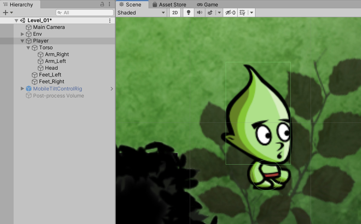
Figure 5.29 – Building a character
Even though all of the player's limbs have now been correctly positioned, the rendering order of the body parts may not be correct yet, as each item will have an identical order in the Sprite Renderer component. We'll look at this next.
Adjusting the sorting order
With the limbs having the same draw order, Unity could potentially render them in any order, thereby allowing arms to appear in front of the head, legs to appear in front of the body, and so on. To correct this, do the following:
- Select each limb.
- In the Inspector window, on the Sprite Renderer component, assign an appropriate value to the Order in Layer field, taking care that it's higher than the world background order and less than the world foreground order.
I've assigned the following values:
- Body = 103
- Head = 105
- Left arm = 102
- Right arm = 104
- Left leg = 100
- Right leg = 101
Tip
When assigning a sorting order to objects in your game, it's a good idea to leave gaps in-between the orders. For example, we may, in the future, want to add a scarf to the player. Ideally, the scarf should be drawn in-between the body and head. As the body is assigned a sort order of 103 and the head a value of 105, we can assign the scarf a sorting order of 104, and it will fit in nicely. If there were no gap between the numbers, we would then have to adjust the sorting value of the head and body to accomplish the same task. This isn't the end of the world for smaller projects, such as this one, but as your project's complexity grows, you may find that having that gap between the sorting order can save you significant time in the future.
Now that the player looks the part, let's make sure they also act the part by adding them to the game's physics engine.
Adding the player to the physics engine
The rendering order for limbs has now been configured successfully. Now, let's set up collisions and physics for the player:
- Add two colliders – a Circle Collider 2D to approximate the character's feet, allowing us to determine when the character is in contact with the ground, and a Box Collider 2D to approximate most of the body, including the head, as shown in the following screenshot:

Figure 5.30 – Adding two colliders to the Player object – Circle Collider and Box Collider
The Circle Collider is of particular importance because it's the primary means to determine whether the character is touching the ground. For this reason, a Physics Material should be assigned to this collider to prevent friction effects from stopping or corrupting character motion as it moves around the scene.
- Create a new physics material by right-clicking in the empty space in the Project panel and selecting Create | Physics 2D Material from the context menu.
- Name the material Low Friction.
- Select the Physics2D material in the Project panel, and from the Inspector window, change the Friction setting to 0.1.
- Drag and drop the Physics2D material from the Project panel into the Material slot for the Circle Collider 2D component on the Player object, as shown in the preceding screenshot.
By using this material, the character will interact with the level more realistically. Lastly, add a Rigidbody 2D to our character:
- Select the Player object.
- Add the component using the application menu; that is, Component | Physics 2D | Rigidbody 2D.
- Set both Linear Drag and Gravity Scale to 3.
- Set Collision Detection to Continuous for more accurate collision detection.
- Freeze the rotation of the object on the Z-axis because the player character should never rotate:

Figure 5.31 – Configuring the player character for physics
Now, you have a fully completed physical object representing the player. Great work! As the player can now interact with the world, it's a good time to look at moving the player using a custom script.
Moving the player
The game, as it currently stands, features an environment with collision data and a multipart player object that interacts and responds to this environment. The player, however, cannot yet be controlled. We'll correct this situation now as we explore controller functionality further by writing and implementing a player control script.
Writing the movement script
The user will have two main input mechanics; namely, movement (walking left and right) and jumping. This input will be read using CrossPlatformInputManager, which is a native Unity package that was imported during the project creation phase. Let's take a look:
- Open the Assets | Standard Assets | CrossPlatformInput | Prefabs folder and drag and drop the MobileTiltControlRig prefab into the scene. This prefab lets you read input data across a range of devices, mapping directly to the horizontal and vertical axes that we've already seen in previous chapters.
- Create a new C# script named PlayerControl.cs and attach it to the Player character. This script will use the cross-platform input object we just added to the scene:
public class PlayerControl : MonoBehaviour
{
private bool GetGrounded()
{
Vector2 CircleCenter = new Vector2(transform.position.x, transform. position.y)+ FeetCollider.offset;
Collider2D[] HitColliders = Physics2D.OverlapCircleAll(CircleCenter, FeetCollider.radius, GroundLayer);
return HitColliders.Length > 0; true;
}
private void Jump()
{
if(!isGrounded || !CanJump)return;
ThisBody.AddForce(Vector2.up * JumpPower);
CanJump = false;
Invoke ("ActivateJump", JumpTimeOut);
}
}
The following points summarize this code sample:
- The PlayerControl class is responsible for handling all player input, making the character move left and right and jump.
- The GetGrounded function detects where any CircleCollider intersects and overlaps with any other collider in the scene on a specific layer. This function indicates whether the player character is touching the ground, and if they are, the player can jump; otherwise, the player cannot jump as they are already airborne. Double-jumping is not allowed in this game!
We're still missing the function that actually reads and applies input. Let's add it now:
public class PlayerControl : MonoBehaviour
{
…
void FixedUpdate ()
{
if(!CanControl || Health <= 0f) { return; }
isGrounded = GetGrounded();
float Horz = CrossPlatformInputManager. GetAxis(HorzAxis);
ThisBody.AddForce(Vector2.right * Horz * MaxSpeed);
if(CrossPlatformInputManager.GetButton(JumpButton)) {
Jump();
}
ThisBody.velocity = new
Vector2(Mathf.Clamp(ThisBody.velocity.x, -MaxSpeed, MaxSpeed),
Mathf.Clamp(ThisBody.velocity.y, -Mathf.Infinity, JumpPower));
if((Horz < 0f && Facing != FACEDIRECTION.FACELEFT)
|| (Hor > 0f && Facing != FACEDIRECTION. FACERIGHT) { FlipDirection(); }
}
Let's summarize the preceding code:
- The movement and motion of the player are set using the RigidBody2D.Velocity variable. More information on this variable can be found online at http://docs.unity3d.com/ScriptReference/Rigidbody2D-velocity.html.
- The FixedUpdate function is used instead of Update to update the movement of the player character because we're working with RigidBody2D – a physics-based component. All physics functionality should be updated in FixedUpdate, which is invoked at a fixed interval each second as opposed to every frame. More information can be found in the Unity online documentation at http://docs.unity3d.com/ScriptReference/MonoBehaviour.FixedUpdate.html.
Important Note
Often, it makes sense to show a snippet of the code, rather than the full listing, as the full code listing may be irrelevant or too long. The previous code listing excludes many of the variables required for it to run, so if you copied it verbatim, you would run into compiler errors. You can always find the full code listings in the relevant chapter folders. For example, PlayerControl.cs can be found in the Chapter05/End/Assets/Scripts folder.
Before we can use our new PlayerControl script, we need to configure the environment as the script expects, which involves adding the level object to a specific layer and adding a collider to the player object. We'll do this now.
Implementing the movement script
For the preceding code to work correctly, a few tweaks must be made to both the scene and player character. Specifically, the GetGrounded function requires that the floor area of the level is grouped as a single layer. This means that the level foreground should be on a distinctive layer from other objects. Let's do this now:
- Create a new layer named Ground. For more information on how to create a layer, see Chapter 4, Continuing the Space Shooter Game.
- Assign the foreground object to the Ground layer.
- After the foreground object has been assigned to the Ground layer, the PlayerControl script requires us to specify the Ground layer. Select the Player object and, from the Inspector window, select the Ground layer for the Ground Layer field, as shown in the following screenshot:

Figure 5.32 – Selecting the Ground layer for collision detection
- In addition, we need to assign a collider to the Feet Collider variable on the PlayerControl script to indicate which collider object should be used for ground collision detection. Drag and drop the Circle Collider 2D component into the Feet Collider slot, as shown in the following screenshot:
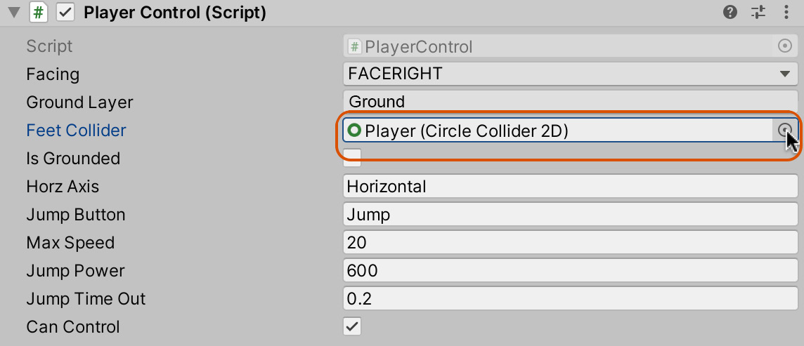
Figure 5.33 – The Feet Collider detects when the character is in contact with the ground
- Now, give the player character a test run. The W, A, S, and D keys (or the arrow keys) will move the player character around, while the spacebar will make the character jump. An example of this can be seen in the following screenshot:

Figure 5.34 – Play testing with the player character
The player character is an ideal candidate for a prefab because it must feature in all the other scenes we create. Let's create a prefab from the player. To do this, drag and drop the Player object into the Project panel in a separate folder called Prefabs (create the folder if it doesn't exist already).
Our work so far has produced a stimulating environment and a character that can traverse that environment. Before moving forward, let's turn our attention to optimization – an issue that should be considered early during development. Optimization refers to the tips and tricks that we can apply to improve runtime performance, as well as our workflow in general. In the next section, we'll look at an optimization technique that's specific to 2D sprites called sprite packing.
Optimizing using sprite packing
Right now, when running the game, Unity will perform a separate draw call for every unique texture or sprite on screen at the time. A draw call refers to a step or process cycle that Unity must run through to correctly display a graphic on-screen, such as a mesh, material, or texture. Draw calls represent a computational expense, and so it's a good idea to reduce them wherever possible.
For 2D games, we can reduce draw calls by batching together related textures, such as all the props for a scene, all the enemies, or all the weapons. By indicating to Unity that a group of textures belong together, Unity can perform internal optimizations that increase render performance. Unity will add all related textures to a single internal texture that it uses instead. To achieve this optimization, follow these steps:
- Select all prop textures: Player, House, Platform, and Gem. These textures are all featured in the Project panel, though not all are used in the game yet.
- From the Inspector window, assign them the same name in the Packing Tag field (Props), as shown in the following screenshot:
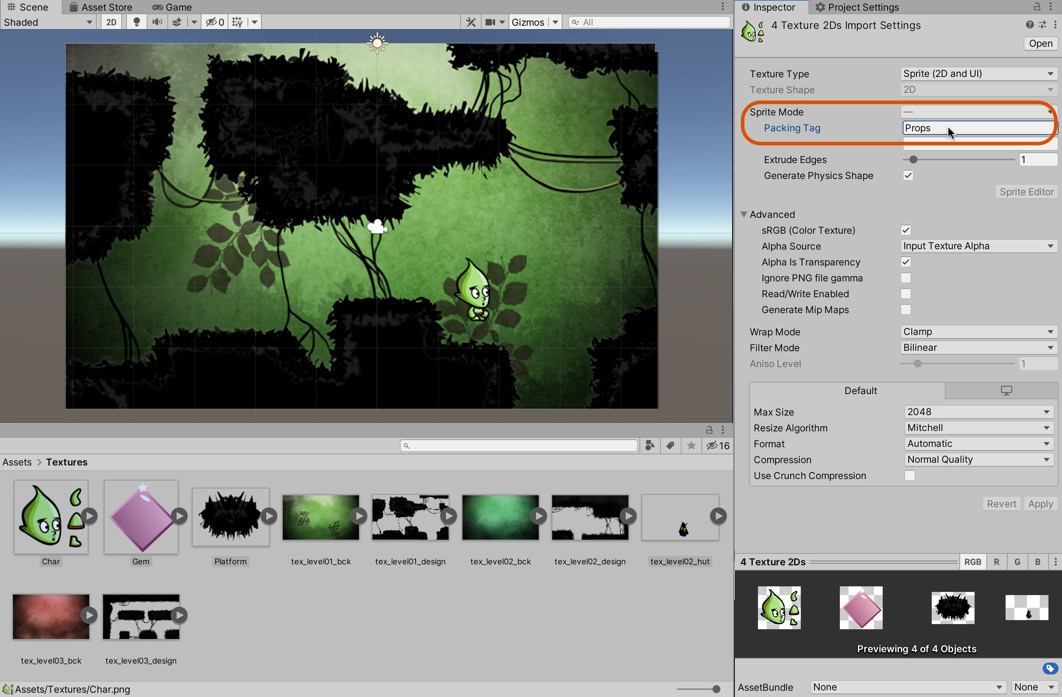
Figure 5.35 – Assigning multiple textures to the same Packing Tag
- Click on Apply.
- Repeat this process for the backgrounds by selecting all the backgrounds and assigning them to the Background packing tag.
When you Play the game next, Unity will automatically batch and organize the textures for optimal performance based on your groupings. This technique can significantly reduce draw calls. On pressing the play button, you may see a loading or progress bar while Unity internally generates a new texture set.
You can view how Unity has organized the textures through the Sprite Packer window. To access this window, select Window | 2D | Sprite Packer from the application menu:
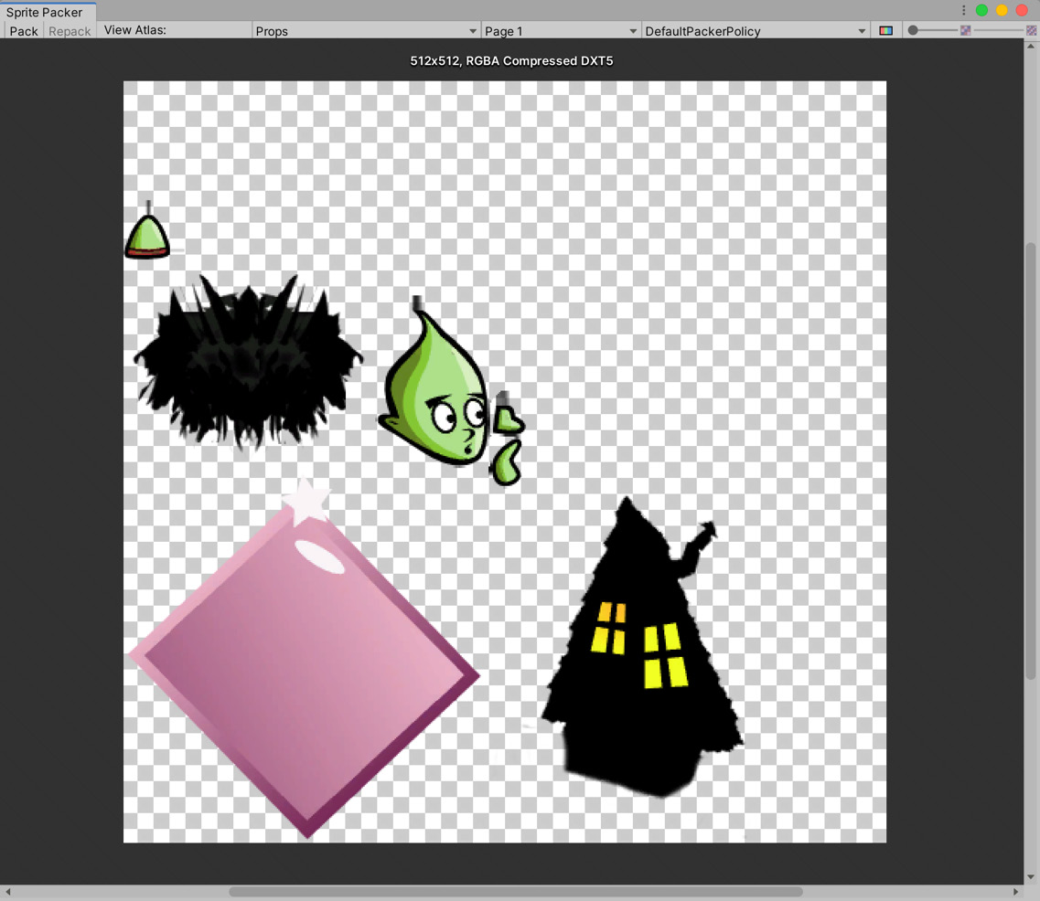
Figure 5.36 – Unity organizes all textures with the same tag into the same texture space as an Atlas
And it's as simple as that. Now, Unity can batch the sprites, thereby reducing the number of draw calls dramatically and increasing the performance of the game.
Summary
Superb work! We've come a long way in this chapter, from a new project to a working 2D game. The player character can navigate a complete 2D environment with 2D physics by moving left, right, and jumping. The player's sprite will dynamically update to match the direction of travel, and by using sprite packing, we've improved runtime performance, which is useful for mobile devices.
By completing this chapter, you've learned the fundamentals of 2D sprites, movement, and physics. By building on this foundation, you will have the required knowledge to create any 2D game, not just a platformer, of your own design.
The next chapter is a big one: in it, we'll complete the game by adding additional levels, obstacles (including moving platforms), a friendly character that assigns a quest – oh, and the quest system itself!
Test your knowledge
Q1. Edge Colliders let you...
A. Create pretty patterns
B. Draw out collider edges
C. Create 3D volumes
D. Create physics animations
Q2. The Sprite Packer is useful for...
A. Creating sprites in rows and columns
B. Grouping sprites onto a single atlas texture
C. Animating sprites
D. Creating multiple color sprites
Q3. Physics Materials can...
A. Help you define how 2D objects behave
B. Scale 2D objects
C. Rotate objects
D. Edit object vertices
Q4. The Sprite Editor lets you...
A. Divide an image into multiple sprites
B. Animate textures
C. Create mesh objects
D. Edit material properties
Further reading
For more information on Unity scripting, take a look at the following links: