Chapter 10. Data Center Security
This chapter covers the following topics:
• Protecting the Data Center Against Denial of Service (DoS) Attacks and Worms
• Data Center Segmentation and Tiered Access Control
• Deploying Network Intrusion Detection and Prevention Systems
• Deploying the Cisco Security Agent (CSA) in the Data Center
Data centers comprise some of the most critical assets within any organization. Typically, applications, databases, and management servers reside in the data center. For this reason, it is extremely important to have the appropriate defense mechanisms in place to protect the data center against security threats. Attacks against data center assets can result in lost business applications and the theft of confidential information. This chapter covers several best practices and recommendations used to increase the security of your data center. These topics include protecting against denial of service (DoS) attacks, worms, information theft, and other security threats. The recommendations in earlier chapters are put into action in this chapter to provide an in-depth defense mechanism against existing and new threats.
Protecting the Data Center Against Denial of Service (DoS) Attacks and Worms
You can implement different mechanisms and technologies on infrastructure components to help mitigate the effects of DoS and worms on your network. The following are some examples:
• SYN cookies in firewalls and load balancers
• Intrusion Prevention Systems (IPSs) and Intrusion Detection Systems (IDSs)
• Cisco NetFlow in the data center
• Data center infrastructure protection
SYN Cookies in Firewalls and Load Balancers
A commonly used distributed denial of service (DDoS) attack is known as SYN-flooding. In this type of attack, the attacker sends a series of TCP SYN packets that typically originate from spoofed IP addresses. The constant flood of SYN packets can prevent servers within the data center from handling legitimate connection requests. You can use firewalls and security appliances such as the Cisco ASA and the Cisco PIX enabled with the SYN cookies algorithm to combat SYN flood attacks. In large data centers, the Cisco Firewall Services Module (FWSM), for the Catalyst 6500 series switches, is typically used for this same purpose. Figure 10-1 demonstrates how TCP synchronization message (SYN) cookies work in the Cisco Adaptive Security Appliance (ASA), the Cisco PIX, and the FWSM for the Cisco Catalyst 6500 switches. In this example, a Cisco FWSM is used.
Figure 10-1. SYN Cookies in FWSM
The following steps are illustrated in Figure 10-1:
1. A client machine attempts a TCP connection to a web server behind the FWSM and sends the initial SYN packet to the firewall.
2. When the embryonic (half-open) connection limit is reached, the Cisco ASA, Cisco PIX, or Cisco FWSM can act as a proxy for the server and generate a SYN-ACK response to the client SYN request. The SYN-ACK reply has a "cookie" in the sequence (SEQ) field of the TCP header. The cookie is a message digest 5 algorithm (MD5) authentication of the source and destination IP addresses and port numbers. All the connection requests are rebuilt from these cookies.
3. The acknowledgement (ACK) packet SEQ field has the value of the cookie+1. In this case, when the FWSM receives an ACK from the client, it "authenticates" the client and allows the connection to the server.
4. The FWSM sends its own SYN packet to the server.
5. The server replies with an ACK.
6. The FWSM sends its SYN-ACK to the server, and the connection is built.
On the Cisco FWSM, you can use the show np command to view SYN cookie statistics. Example 10-1 shows the output of the show np 2 syn command on an FWSM.
Example 10-1. Output of show np 2 syn Command
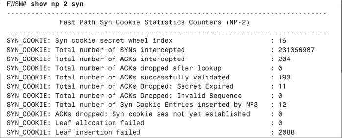
In the highlighted line in Example 10-1, you can see that the total number of intercepted SYN packets is 231356987. This is most definitely indicative of a SYN flood.
Load-balancing solutions such as the Cisco Content Switching Module (CSM) also support SYN cookies. You can deploy the CSM in inline mode or one-arm mode. Figure 10-2 illustrates a CSM configured in inline mode. Traffic from certain applications cannot be load-balanced because of the nature of those applications. In Figure 10-2, the traffic that cannot be load-balanced is labeled as direct traffic.
Figure 10-2. CSM in Inline Mode
In Figure 10-2, the CSM is configured with both physical interfaces that are connected to the network with all traffic passing through the CSM. Figure 10-3 illustrates the one-arm CSM design.
Figure 10-3. CSM in One-Arm Mode

The CSM uses a virtual IP address. In a "one-arm" design, you can combine it with a Cisco FWSM. One of the major benefits of using a CSM one-arm design in combination with the Cisco FWSM is that the CSM protects against DoS attacks directed at its virtual IP address, and the Cisco FWSM protects against attacks directed at non-load-balanced servers.
The use of SYN cookies has certain limitations. For example, SYN cookies cannot carry TCP options that are set up in SYN packets; SYN cookies can carry only an encoding of the maximum segment size (MSS) value of the server. Some TCP options are used for performance and scalability (for example, large windows, selective acknowledgement, and so on). Another limitation of SYN cookies is that they do not protect against established connection attacks.
Note
Established connection attacks are attacks that exploit vulnerabilities after a connection has been established such as a buffer overflow to a specific application.
Intrusion Prevention Systems (IPS) and Intrusion Detection Systems (IDS)
In earlier chapters, you learned the difference between IDS and IPS devices. IDS and IPS appliances and modules are usually placed in the data center distribution center not only to alert an administrator when a security threat has been detected, but also to take action and protect the data center assets. In small environments, one or more IDS/IPS appliances (such as the Cisco 4200 sensors) can be placed in the data center. The Cisco Catalyst 6500 IDS/IPS module (IDSM) is used in larger environments.
The Cisco Security Agent (CSA) provides host-based prevention services that help you protect the servers in the data center from attacks that exploit OS and application vulnerabilities. These two technology solutions (network and host-based) complement each other. Despite the fact that both solutions provide intrusion prevention mechanisms that guard against direct attacks, the technologies are different in numerous ways. Later sections in this chapter cover the deployment of both network and host-based IPS solutions. The benefits and limitations of each solution are discussed in their respective sections.
Cisco NetFlow in the Data Center
Cisco NetFlow provides network traffic visibility that can help in identifying and classifying potential DDoS attempts and other security threats. In addition, it provides valuable information about application usage that can be beneficial for network planning and traffic engineering. You can enable NetFlow in data center infrastructure devices, such as your distribution switches or routers. A new version of NetFlow called Flexible NetFlow is now available on Cisco IOS routers starting with IOS Version 12.4(9)T. Cisco is working to provide this functionality in other platforms such as the Catalyst 6500 series switches.
Note
You can use the Cisco Feature Navigator tool to find information about platform support. To access this tool, go to http://tools.cisco.com/ITDIT/CFN/jsp/index.jsp.
With Flexible NetFlow, you can configure a range of parameters for traffic analysis and data export on a networking device. For instance, you can define your own records by specifying the key and nonkey fields to customize the data collection to your specific requirements. In previous versions of NetFlow, a flow was based on a set of seven IP packet attributes:
• Source IP
• Destination IP
• Source port
• Destination port
• Layer 3 Protocol
• Type of Service (ToS) byte
• Input interface
Flexible NetFlow adds the ability to check other information, such as the number of bytes and packets in a flow. You can also create custom records for functions like quality of service (QoS), bandwidth monitoring, application and end user traffic profiling, and security monitoring.
The main limitation is that, currently, Flexible NetFlow is not supported in the Cisco Catalyst 6500. In most cases, it is recommended that you enable NetFlow at the data center distribution switches. In large data centers, Cisco Catalyst 6500 switches are used as distribution switches. However, the benefits of NetFlow Versions 5 and 9 are still extremely valuable, because NetFlow is one of the most helpful tools for identifying and classifying security threats. In addition, you can use network monitoring tools such as the Cisco Security Monitoring, Analysis, and Response System (CS-MARS) to analyze NetFlow and other telemetry data from many different network devices.
Cisco Guard
The Cisco Detector and Cisco Guard provide anomaly detection and attack mitigation features. You can place them in large data centers to divert traffic directed at the target host for analysis and filtering, so that legitimate transactions can still be processed while illegitimate traffic is dropped. On the other hand, in most cases small, medium, and large enterprises place their Cisco Guard at their Internet edge or subscribe to managed services provided by service providers.
Note
The managed service solution is called Clean Pipes. Cisco has detailed information about the Clean Pipes solution at http://www.cisco.com/en/US/netsol/ns615/networking_solutions_sub_solution.html.
Data Center Infrastructure Protection
The infrastructure protection best practices that you learned in Chapter 2, "Preparation Phase," also apply in the data center. For example, you should harden control protocols as a basic security precaution on all applicable devices in the data center. In addition, you should disable unnecessary services on infrastructure components and implement device protection mechanisms, such as infrastructure access control lists (iACLs) and Control Plane Policing (CoPP). These device protection mechanisms will help you greatly in case of worm outbreaks, DDoS, or even in case of an anomaly other than a security threat (that is, a misconfigured application).
Tip
Remember to implement basic best-practice recommendations such as hardening device authentication, hardening Simple Network Management Protocol (SNMP), using Network Time Protocol (NTP), and all others that you learned in Chapter 2.
You can also develop configuration templates for data center access switch ports where servers reside. Basic Layer 2 security mechanisms, such as limits on the number of MAC addresses that the server can originate on a port, can be included in the configuration template. You can also disable the Cisco Discovery Protocol (CDP) when it is not needed; be careful, however, because certain applications use CDP for legitimate transactions. Example 10-2 shows a basic template.
Example 10-2. Data Center Access Switch Port Template
interface GigabitEthernet2/4
no ip address
switchport
switchport access vlan 100
switchport mode access
spanning-tree portfast
switchport port-security maximum 2
switchport port-security violation shutdown
spanning-tree bpduguard enable
no cdp enable
The highlighted commands in Example 10-2 enable port security and BPDU guard and disable CDP.
Note
An important point about port security is that it does not interoperate well with virtual servers because they may carry multiple MAC addresses of virtual hosts. You should also be careful when implementing port security with certain server failover mechanisms. In some environments, servers with multiple network interface cards (NIC) may share the same MAC address between interfaces when a failover occurs.
For antispoofing protection, you can also enable Unicast Reverse Path Forwarding (Unicast RPF) in routers, security appliances such as the Cisco ASA, or in the Cisco FWSM. In the data center, it is most common to deploy Unicast RPF on the firewalls (Cisco ASA or FWSM). With Unicast RPF, if traffic enters the outside or untrusted interface from an address that is known to the routing table, but it resides on the inside interface, the firewall drops the packet. Similarly, if traffic enters the inside interface from an unknown source address, the firewall drops the packet to prevent spoofed attacks. You can enable Unicast RPF on the Cisco ASA, Cisco PIX, or Cisco FWSM with the ip verify reverse-path command, as shown in the following example:
FWSM(config)#ip verify reverse-path interface outside
FWSM(config)#ip verify reverse-path interface inside
In the previous example, Unicast RPF is enabled in the outside and inside interfaces. Because firewalls require traffic path symmetry, in most cases, Unicast RPF can provide great benefits without impacting traffic flow.
Data Center Segmentation and Tiered Access Control
By isolating different types of servers and services, you can use segmentation and tiered access control in your data center to provide a multilayered architecture while adding security. The easiest way to segment your data center is to configure different Layer 2 domains or VLANs. In addition, you can use firewalls for policy enforcement between each segment. By using private VLANs, you can also use segmentation that is local to the VLAN. This helps in preventing a compromised or infected server from affecting adjacent systems. In a multitier architecture, you separate systems based on the different functions they handle. For example, you can separate the presentation, business logic, and database layers, as illustrated in Figure 10-4.
Figure 10-4. Multitier Server Segmentation Example
In Figure 10-4, a web server farm is separated from the application and the database servers. This is done to protect the application and the database in case the web servers are compromised.
You can also segment the data center by separating other types of application servers and devices. It is a best practice to separate all your management servers. For example, your management segment can include your TACACS+, RADIUS, SNMP, and any configuration management servers such as CiscoWorks, Cisco Security Manager, CS-MARS, and others.
Figure 10-5 shows how management servers can also be separated from the rest of the data center.
Figure 10-5. Management Servers Segmented

As previously mentioned, you can segment your data center simply by configuring separate VLANs; however, this does not truly provide a complete solution that allows you to enforce your security policies between each boundary. Therefore, you can configure firewalls to provide additional security while allowing the necessary traffic to pass between segments.
Note
You can also segment your data center by configuring Virtual Routing and Forwarding (VRF) interfaces with Multiprotocol Label Switching (MPLS) or by using VRF-Lite. This is more suitable for large environments and requires your staff to be familiar with more advanced routing features such as MPLS. The next section explains how to achieve segmentation using separate VLANs and the Cisco FWSM for policy enforcement and additional protection.
Segmenting the Data Center with the Cisco FWSM
In this section, you will learn how to take advantage of some of the Cisco FWSM features to segment your data center. It covers the modes of operation of the FWSM, design considerations, and configuration steps.
Cisco FWSM Modes of Operation and Design Considerations
You can use the Cisco FWSM not only to segment your data center, but also to enforce policy and to provide additional security benefits such as stateful and deep packet inspection. You can configure the Cisco FWSM in two different modes:
• Routed mode: The default behavior. The Cisco FWSM in routed mode acts as a Layer 3 device supporting features such as Network Address Translation (NAT) and routing protocols. In most cases, when a Cisco FWSM is deployed in routed mode in the data center, it becomes the default gateway for a majority of the servers.
• Transparent mode: The Cisco FWSM acts as a Layer 2 device. One of the major benefits of transparent mode is that you do not have to worry about readdressing your infrastructure when deploying a new firewall within your data center, because the firewall acts as a bridge between the external and internal network. On the other hand, when you are operating in transparent mode, the FWSM does not support features such as NAT routing protocols and some specific inspections engines that depend on NAT.
Note
Routed and transparent modes are also supported in the Cisco ASA and the Cisco PIX security appliances. In smaller environments, you can deploy the Cisco ASA at the data center. The configuration is identical except that the Cisco FWSM runs in the Catalyst 6500 series switches or in the Cisco 7600 series routers; therefore, specific configuration steps are needed in the switch or the router. This subject is covered later in this section.
Figure 10-6 shows a Cisco FWSM configured in transparent mode.
Figure 10-6. Cisco FWSM in Transparent Mode

In Figure 10-6, the Cisco FWSM outside interface resides on VLAN 100, and the inside interface resides on VLAN 101. Both interfaces belong to the same network subnet (10.10.10.0/24). The Cisco FWSM must have a management IP address configured for traffic to pass through it when configured in transparent mode. In this example, the management IP address is 10.10.10.123.
You can take advantage of the virtualization capabilities of the Cisco FWSM to segment your data center. You can partition the Cisco FWSM into multiple virtual firewalls, known as security contexts. Each of these virtual firewalls has its own configuration enforcing separate security policies to each segment in the data center.
Note
When you have multiple virtual security contexts configured, it is similar to having multiple standalone firewalls. Many features are supported when you configure the Cisco FWSM with multiple contexts, including routing tables, firewall features, and management. However, certain features are not supported, including dynamic routing protocols.
The Cisco ASA and Cisco PIX security appliances also support virtual firewalls. Their behavior is similar to the Cisco FWSM.
Figure 10-7 illustrates the four modes of operations of the Cisco FWSM:
• Single context routed mode
• Single context transparent mode
• Multiple context routed mode
• Multiple context transparent mode
Figure 10-7. Cisco FWSM Modes of Operation

Figure 10-8 shows a Cisco FWSM configured with three different contexts. Each context includes its own configuration to protect each data center segment.
Figure 10-8. Cisco FWSM Contexts
In Figure 10-8, the Cisco FWSM contexts separate the web servers, applications servers, and database servers. The following are the context names:
• Webservers
• APPservers
• DBservers
The inside interface of context Webservers resides in VLAN 10. The inside interface of context APPservers is in VLAN 20, and the context DBserver inside interface is in VLAN 30.
Configuring the Cisco Catalyst Switch
In the Cisco Catalyst switch, you must create the necessary VLANs and assign those to the Cisco FWSM. Example 10-3 shows the commands used to create VLANs 10, 20, 30, and 40 in the Cisco Catalyst 6500 switch.
Example 10-3. Creating the VLANs in the Switch
vlan 10
name webservers
!
vlan 20
name appservers
!
vlan 30
name dbservers
!
vlan 40
name tocorpnetwork
Each VLAN entry is configured with a descriptive name based on the data center segment. You then have to assign the VLANs to the Cisco FWSM. Example 10-4 shows how you can create firewall VLAN groups and then assign the group to the Cisco FWSM.
Example 10-4. Assigning the VLANs to the Cisco FWSM
firewall multiple-vlan-interfaces
firewall module 2 vlan-group 1
firewall vlan-group 1 10,20,30,40
In Example 10-4, a VLAN group with ID of 1 is configured. This VLAN group includes VLANs 10, 20, 30, and 40 and is applied to the Cisco FWSM with the firewall module 2 vlan-group 1 command. The number 2 indicates that the Cisco FWSM resides on the second slot in the Cisco Catalyst 6500 switch.
Tip
For security reasons, by default, only one switch virtual interface (SVI) can exist between the switch and the Cisco FWSM. You might also choose to use multiple SVIs in routed mode so that you do not have to share a single VLAN for the outside interface. You can use the firewall multiple-vlan-interfaces command to allow you to add more than one SVI to the Cisco FWSM. In this example, the outside interfaces of each context reside on VLAN 40.
Creating Security Contexts in the Cisco FWSM
When you configure the Cisco FWSM in multiple context modes, you add and manage all security contexts in the system space or system configuration mode. By default, a context named admin is created. The admin context is just like any other context, except that when a user logs into the admin context, that user has system administrator rights and can access the system and all other contexts. The admin context is not restricted in any way and can be used as a regular context. However, because logging into the admin context grants you administrator privileges over all contexts, you might need to restrict access to the admin context for appropriate users.
Tip
The admin context configuration must reside on flash memory and not on a remote system. If your system is already in multiple context mode, or if you convert from single mode, the admin context is created automatically as a file on the internal flash memory called "admin.cfg." This context is named "admin." If you do not want to use admin.cfg as the admin context, you can change the admin context.
Because the default mode in the Cisco FWSM is single routed mode, to start creating security context, you need to change the FWSM to multiple mode. You can use the mode multiple command from configuration mode to enable multiple mode, as shown here:
FWSM(config)# mode multiple
Note
After you enter the mode multiple command, you are prompted to reboot the Cisco FWSM.
Example 10-5 shows the context configuration on the Cisco FWSM that was pictured in the previous example.
Example 10-5. Creating the Security Contexts
context webservers
description Webserver segment
allocate-interface vlan40 int1
allocate-interface vlan10 int2
config-url disk:/webservers.cfg
!
context appservers
description Application server segment
allocate-interface vlan50 int1
allocate-interface vlan20 int2
config-url disk:/appservers.cfg
!
context dbservers
description Database servers segment
allocate-interface vlan60 int1
allocate-interface vlan30 int2
config-url disk:/dbservers.cfg
The contexts webservers, appservers, and dbservers are defined in Example 10-5. Each security context or virtual firewall has two interfaces.
In this example, the configuration of each security context is stored locally and not on an external server. After the contexts have been created, you can change to any of them by using the changeto context command, as shown here:
FWSM(config)# changeto context webservers
FWSM/webservers(config)#
Notice that the prompt changes with the hostname followed by the context name you are currently configuring.
Configuring the Interfaces on Each Security Context
The interface identifiers on each security context that were previously created were int1 for the outside interface and int 2 for the inside interface. Figure 10-9 shows the IP address configuration of the interfaces on each security context (virtual firewall).
Figure 10-9. IP Address Configuration on Each Virtual Firewall
Example 10-6 shows the configuration of the interfaces on the Webservers security context.
Example 10-6. webservers Security Context IP Address Configuration
interface int1
nameif outside
security-level 0
ip address 10.10.10.1 255.255.255.0
!
interface int2
nameif inside
security-level 100
ip address 192.168.10.1 255.255.255.0
Example 10-7 shows the configuration of the interfaces on the APPservers security context.
Example 10-7. appservers Security Context IP Address Configuration
interface int1
nameif outside
security-level 0
ip address 10.10.10.2 255.255.255.0
!
interface int2
nameif inside
security-level 100
ip address 192.168.20.1 255.255.255.0
Example 10-8 shows the configuration of the interfaces on the DBservers security context.
Example 10-8. dbservers Security Context IP Address Configuration
interface int1
nameif outside
security-level 0
ip address 10.10.10.3 255.255.255.0
!
interface int2
nameif inside
security-level 100
ip address 192.168.30.1 255.255.255.0
Configuring Network Address Translation
The goal is to configure static NAT for each server residing on each security context. Three systems reside in the web server segment (context webservers). This is illustrated in Figure 10-10.
Figure 10-10. webserver IP Address Configuration
Table 10-1 lists the physical IP addresses of each web server with the statically translated address.
Table 10-1. Web Servers NAT Mapping

Example 10-9 shows the static NAT configuration for each server on the webservers security context.
Example 10-9. webservers Context NAT Configuration
static (inside,outside) 10.10.10.51 192.168.10.51 netmask 255.255.255.255
static (inside,outside) 10.10.10.52 192.168.10.52 netmask 255.255.255.255
static (inside,outside) 10.10.10.53 192.168.10.53 netmask 255.255.255.255
Two application servers are in the data center as illustrated in Figure 10-11. They are protected by the virtual firewall (context) called APPservers.
Figure 10-11. Application Servers IP Address Configuration

Table 10-2 lists the physical IP addresses of each application server along with the statically translated address.
Table 10-2. Application Servers NAT Mapping

Example 10-10 shows the static NAT configuration for each server on the appservers security context.
Example 10-10. appservers Context NAT Configuration
static (inside,outside) 10.10.20.71 192.168.20.71 netmask 255.255.255.255
static (inside,outside) 10.10.20.72 192.168.20.72 netmask 255.255.255.255
The data center has two database servers, as illustrated in Figure 10-12. They are protected by the virtual firewall (context) called DBservers.
Figure 10-12. Database Servers IP Address Configuration
Table 10-3 lists the physical IP addresses of each application server along with the statically translated address.
Table 10-3. Database Servers NAT Mapping

Example 10-11 shows the static NAT configuration for each server on the DBservers security context.
Example 10-11. dbservers Context NAT Configuration
static (inside,outside) 10.10.30.101 192.168.30.101 netmask 255.255.255.255
static (inside,outside) 10.10.30.102 192.168.30.102 netmask 255.255.255.255
Controlling Access with ACLs
It is recommended that you configure ACLs on both interfaces of each security context for more granular security policy enforcement. You can tune the ACLs based on your security policies and application usage. The ACLs that are configured on each of the security contexts in this example only allow the necessary traffic for each server and application.
Table 10-4 lists the protocols and ports that need to be allowed on the webservers security context.
Table 10-4. Protocols and Ports Used by the webservers

[1] SSH = Secure Shell
[2] SCP = Secure Copy Protocol
[3] DNS = Domain Name System
[4] UDP = User Datagram Protocol
Users connect to the web servers via HTTP and HTTPS; therefore, this traffic is allowed on the outside interface in the webservers context. The web servers are Linux-based machines. The administrator transfers files over SCP and connects to the server command-line interface (CLI) via SSH. In addition, the administrator uses a custom management application to install software and patches on the systems (Mgmt-App). This traffic from the management network (10.10.100.0/24) needs to be allowed.
The web servers themselves need to access an application called App-X running on the servers in the APPservers context over TCP port 987. DNS resolution and SYSLOG must also be allowed to external servers. Example 10-12 shows the ACLs configured in the Webservers context allowing the previously mentioned ports and protocols.
Example 10-12. webservers Context ACL Configuration

In Example 10-12, ACLs are configured to allow the traffic specified in Table 10-4. The ACL named inbound-traffic is applied to the outside interface, and the ACL named outbound-traffic is applied to the inside interface. Notice that the web server IP addresses in the inbound-traffic ACL are the translated addresses. However, because the outbound-traffic ACL is applied to the inside interface, the physical IP addresses are used as the source. The web servers must access two DNS servers. The primary DNS server is 10.10.111.11, and the secondary is 10.10.111.12. The IP address of the SYSLOG server is 10.10.100.100.
Table 10-5 lists the necessary protocols and ports that need to be allowed on the appservers security context.
Table 10-5. Protocols and Ports Used by the appservers
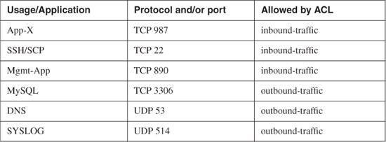
The web servers communicate with the application (App-X) running on the servers in the APPservers context over TCP port 987. Similar to the web servers, the administrator transfers files over SCP and connects to the server CLI via SSH. In addition, the administrator uses a custom management application to install software and patches on the systems (Mgmt-App). This management traffic from the management network (10.10.100.0/24) needs to be allowed. The application servers connect to the database servers running MySQL over TCP port 3306. DNS resolution and SYSLOG must also be allowed to external servers.
Example 10-13 shows the ACLs configured in the appservers context allowing the ports and protocols listed in Table 10-6.
Table 10-6. Protocols and Ports Used by the dbservers

Example 10-13. appservers Context ACL Configuration
access-list inbound-traffic remark INBOUND TRAFFIC TO APPSERVERS
access-list inbound-traffic extended permit tcp host 10.10.10.51 host 10.10.20.71
eq 987
access-list inbound-traffic extended permit tcp host 10.10.10.52 host 10.10.20.71
eq 987
access-list inbound-traffic extended permit tcp host 10.10.10.53 host 10.10.20.71
eq 987
access-list inbound-traffic extended permit tcp host 10.10.10.51 host 10.10.20.72
eq 987
access-list inbound-traffic extended permit tcp host 10.10.10.52 host 10.10.20.72
eq 987
access-list inbound-traffic extended permit tcp host 10.10.10.53 host 10.10.20.72
eq 987
access-list inbound-traffic extended permit tcp 10.10.100.0 255.255.255.0 host
10.10.20.71 eq 22
access-list inbound-traffic extended permit tcp 10.10.100.0 255.255.255.0 host
10.10.20.72 eq 22
access-list inbound-traffic extended permit tcp 10.10.100.0 255.255.255.0 host
10.10.20.71 eq 890
access-list inbound-traffic extended permit tcp 10.10.100.0 255.255.255.0 host
10.10.20.72 eq 890
access-group inbound-traffic in interface outside
!
access-list outbound-traffic remark OUTBOUND TRAFFIC FROM APPSERVERS
access-list outbound-traffic extended permit tcp host 192.168.20.71 host
10.10.30.101 eq 3306
access-list outbound-traffic extended permit tcp host 192.168.20.72 host
10.10.30.101 eq 3306
access-list outbound-traffic extended permit tcp host 192.168.20.71 host
10.10.30.102 eq 3306
access-list outbound-traffic extended permit tcp host 192.168.20.72 host
10.10.30.102 eq 3306
access-list outbound-traffic extended permit udp host 192.168.20.71 host
10.10.111.11 eq 53
access-list outbound-traffic extended permit udp host 192.168.20.72 host
10.10.111.11 eq 53
access-list outbound-traffic extended permit udp host 192.168.20.71 host
10.10.111.12 eq 53
access-list outbound-traffic extended permit udp host 192.168.20.72 host
10.10.111.12 eq 53
access-list outbound-traffic extended permit tcp host 192.168.20.71 host
10.10.100.100 eq 514
access-list outbound-traffic extended permit tcp host 192.168.20.72 host
10.10.100.100 eq 514
access-group outbound-traffic in interface inside
In Example 10-13, ACLs are configured to allow the traffic specified in Table 10-5. The ACL named inbound-traffic is applied to the outside interface, and the ACL named outbound-traffic is applied to the inside interface.
Table 10-6 lists the necessary protocols and ports that need to be allowed on the DBservers security context.
The application servers communicate with the MySQL database running on the servers in the DBservers context over TCP port 3306. Linux-based servers also exist, and the administrator transfers files over SCP and connects to the server CLI via SSH. As with the other servers, the administrator uses the custom management application to install software and patches on the systems (Mgmt-App). This management traffic from the management network (10.10.100.0/24) needs to be allowed. DNS resolution and SYSLOG must also be allowed to external servers.
Example 10-14 shows the ACLs configured in the APPservers context allowing the ports and protocols listed in Table 10-6.
Example 10-14. dbservers Context ACL Configuration
access-list inbound-traffic remark INBOUND TRAFFIC TO DATABASE SERVERS
access-list inbound-traffic extended permit tcp host 10.10.20.71 host 10.10.30.101
eq 3306
access-list inbound-traffic extended permit tcp host 10.10.20.72 host 10.10.30.101
eq 3306
access-list inbound-traffic extended permit tcp host 10.10.20.71 host 10.10.30.102
eq 3306
access-list inbound-traffic extended permit tcp host 10.10.20.72 host 10.10.30.102
eq 3306
access-list inbound-traffic extended permit tcp 10.10.100.0 255.255.255.0 host
10.10.30.101 eq 22
access-list inbound-traffic extended permit tcp 10.10.100.0 255.255.255.0 host
10.10.30.102 eq 22
access-list inbound-traffic extended permit tcp 10.10.100.0 255.255.255.0 host
10.10.30.101
eq 890
access-list inbound-traffic extended permit tcp 10.10.100.0 255.255.255.0 host
10.10.30.102
eq 890
access-group inbound-traffic in interface outside
!
access-list outbound-traffic remark OUTBOUND TRAFFIC FROM DATABASE SERVERS
access-list outbound-traffic extended permit udp host 192.168.30.101 host
10.10.111.11 eq 53
access-list outbound-traffic extended permit udp host 192.168.30.102 host
10.10.111.11 eq 53
access-list outbound-traffic extended permit udp host 192.168.30.101 host
10.10.111.12 eq 53
access-list outbound-traffic extended permit udp host 192.168.30.102 host
10.10.111.12 eq 53
access-list outbound-traffic extended permit tcp host 192.168.30.101 host
10.10.100.100 eq 514
access-list outbound-traffic extended permit tcp host 192.168.30.102 host
10.10.100.100 eq 514
access-group outbound-traffic in interface inside
In Example 10-14, ACLs are configured to allow the traffic specified in Table 10-6. The ACL named inbound-traffic is applied to the outside interface, and the ACL named outbound-traffic is applied to the inside interface.
Virtual Fragment Reassembly
The Cisco FWSM, Cisco ASA, and Cisco PIX security appliances drop fragments. However, many different applications generate fragments. If you enable fragment forwarding, you open yourself to fragment attacks (like the ones defined in RFC 1858). You can use the Virtual Fragment Reassembly feature to protect against this type of attack. You enable Virtual Fragment Reassembly with the fragment command. In the following example, the Cisco FWSM is limiting its fragment buffer size to 200 packets on its outside and inside interfaces.
fragment size 200 outside
fragment size 200 inside
Tip
By using the chain and timeout options in the fragment command, you can also define the maximum number of fragments to be chained together and the length of time the Cisco FWSM waits for the fragments to arrive before discarding them.
Deploying Network Intrusion Detection and Prevention Systems
You can use network IDS/IPS appliances in small-to-medium organizations or the Cisco IDSM-2 for the Cisco Catalyst 6500 series switches in larger organizations. The implementation of each solution depends on the size of your data center and its requirements. When designing a network IDS/IPS solution for the data center, for both scalability and manageability, you should reduce the amount of traffic that is sent to the sensor. You should also avoid sending duplicate frames to the IDS/IPS sensors or modules. At the same time, you should avoid the situation in which you must change existing ACLs or VACLs before being able to implement an IDS/IPS solution. In most cases, you want to create several SPAN sessions to be able to send the traffic to multiple IDS/IPS devices. This section includes several best practices to use when you deploy an IDS/IPS solution in your data center.
Sending Selective Traffic to the IDS/IPS Devices
Depending on the size of your data center, you may use one or more IPS/IDS devices. In large data centers, you can use several IDSMs to monitor the activity within your server farms. Figure 10-13 illustrates a data center with three different IDSMs installed on each Cisco Catalyst 6500 along with the Cisco FWSM.
Figure 10-13. IDSMs Deployed in the Data Center

In some cases, exposing IPS/IDS sensors to all the traffic that flows within a data center can oversubscribe the IPS/IDS devices. To avoid performance problems in the data center, some administrators prefer to use only IDS features (promiscuous inspection) instead of inline IPS services. Others prefer to limit the number of protocols or the type of traffic to which a sensor is assigned. For example, in the high-level data center topology illustrated in Figure 10-13, you can selectively send traffic from each data center segment to specific IDSMs. For instance, you may want to send all web-related traffic on the webservers segment to the first IDSM. Similarly, you may want to send all traffic that traverses the application server segment to the second IDSM, and traffic destined and originated by the database servers to the third IDSM. This is illustrated in Figure 10-14.
Figure 10-14. Sending Selective Traffic to the IDS/IPS Devices
Based on VLAN information, you can use a SPAN session to differentiate traffic on multiple ports. This is supported on the Cisco Catalyst 6500 starting from Cisco IOS Versions 12.2(18)SXD and 12.1(24)E. You can configure a single SPAN session to capture traffic from the three VLANs and send traffic from each VLAN to a specific IDSM or external sensor. With this configuration, the IDS/IPS devices can inspect client-to-server traffic, locally switched traffic, and server-to-server routed traffic.
Alternatively, you can use VACL capture. You do this by simply configuring three VACLs with the forward capture action and assigning them to the three different segments. You assign IDSM-A to the web servers segment, IDSM-B to the application servers segment, and IDSM-C to the database segment.
In certain trunk environments, the use of VACLs achieves half the goal of this design. The IDSMs may still experience substantial noise traffic. In addition to this, you have to modify the security VACLs that might already be in place in the data center to include the capture action for the traffic that you want to monitor. To address this problem, you can use RSPAN and VACL redirect together. You can configure RSPAN to create a copy of the traffic from all the ports connecting the Catalyst 6500 to the core and to the server farms. All these frames are locally copied onto an RSPAN VLAN which is a special VLAN that is equally visible to three IDSMs. Then you configure VACL redirection. This does not permit or deny the traffic, it simply redirects the traffic to the desired IDSM. One VACL entry specifies that traffic to the web servers on the RSPAN VLAN be redirected to IDSM-1; another VACL entry specifies that traffic destined to the application servers on the RSPAN VLAN be redirected to IDSM-2; the same applies for the database server traffic to IDSM-3.
Note
You can find a detailed white paper on how to use RSPAN with VACLs for granular traffic analysis at http://www.cisco.com/warp/public/cc/pd/si/casi/ca6000/prodlit/rspan_wp.pdf.
Monitoring and Tuning
Monitoring tools such as CS-MARS help not only to identify and detect security threads, but also to reduce steps in the tuning process. Tuning is the process of managing and minimizing the number of false positives and false negatives that the network IDS/IPS device reports. As you learned in previous chapters, a false positive is a benign network activity mistakenly identified as malicious by the sensor. A false negative is malicious network activity mistakenly identified as benign or not detected by the sensor. To tune sensors, you enable, disable, or modify the signatures used in the network. The tuning process is one of the most crucial operational tasks that you perform when increasing the security of your data center. In Chapter 3, "Identifying and Classifying Security Threats," you learned best practices to use when deploying IDS/IPS devices. These same best practices apply in the data center.
Deploying the Cisco Security Agent (CSA) in the Data Center
CSA provides several security features that are more robust than a traditional antivirus or a personal firewall. CSA not only protects against viruses, worms, and direct attacks, but it also protects against day-zero threats. CSA plays an important role in data center security.
CSA Architecture
In the CSA solution architecture, a central management center maintains a database of policies and information about the workstations and servers on which the CSA software is installed. Agents register with the Cisco Security Agent Management Center (CSA-MC). Subsequently, the CSA-MC checks its configuration database and deploys a configured policy for that particular system.
Note
Starting with CSA Version 5.1, the CSA-MC is a standalone system. Prior to Version 5.1, CSA-MC was part of the Cisco Works VPN and Security Management System (VMS).
The CSA software constantly monitors all activity on the end host and polls to the CSA-MC at configurable intervals for policy updates. The agent sends events and alerts to the global event manager of the CS-AMC. The global event manager inspects the event logs and then alerts the administrator or triggers the agent to take action based on the specific alert.
Note
All the communication between the agents and the CSA-MC is via Secure Socket Layer (SSL). The administrator also connects to the CSA-MC via SSL to manage and monitor the agents.
Configuring Agent Kits
As previously mentioned, CSA-MC comes with preconfigured agent kits that can be used to fulfill initial security needs. However, CSA-MC allows you to create custom agent kits to fit your specific requirements. For example, you can create different agent kits for the various servers within your data center. To create a new agent kit, complete the following steps:
Step 1. Choose Systems > Agent Kits from the CSA-MC console.
Step 2. Click New at the bottom of the page displayed. A dialog box appears asking you to specify the operating system on which the agent kit will be applied.
Step 3. Enter a name and description for the new agent kit. For example, you can create agent kits for the web servers, application, and database servers in the examples in the previous sections.
Step 4. Select the groups that will be associated with this agent kit. You can select from predefined groups designed for different type of servers.
Step 5. Optionally, you can select to reboot the system after the CSA installation is complete. You can also select a quiet install to avoid end-user interaction.
Step 6. Click Make Kit to create the new agent kit.
Step 7. Click Generate Rules to generate all pending rules. A new window appears with information about the rule generation. After you have made the appropriate selections, click Generate.
Step 8. All rules and configuration changes are applied at this point. A summary window appears if the rule generation completes successfully.
Phased Deployment
When you start your CSA deployment, select the initial hosts on which CSA will be installed based on the following guidelines:
• Select at least one host per each distinct application or server environment.
• During the pilot, make the test host a mirror sample of the production systems.
• When installing CSA on servers, use a test machine for each server type to ensure that there is no negative impact from the CSA agent software installation.
• Create a group for each type of application environment to be protected.
Building and tuning of CSA policies is a continuous task. You need to have the proper staff and procedures to minimize the administrative burden. The security staff is responsible not only for maintaining the CSAMC policies, but also for creating and organizing appropriate exception rules and for monitoring user activity. You can organize the exception rules as follows:
• Create a global exception policy to allow legitimate traffic and application behavior that is required on all the systems within the organization. Subsequently, add these global exception rules to this exception policy.
• Create one exception policy for each group.
• Apply these policies to their respective groups and collect all necessary data to complete any additional tuning.
The following summarizes the steps that your security staff should use when deploying the agent kits throughout the organization:
Step 1. Deploy the CSA agents in test mode throughout your organization.
Step 2. Collect and analyze results. Subsequently, start policy tuning (as needed).
Step 3. Enable protection mode.
Step 4. Make sure that your security, operations, and engineering staff members are comfortable with the support of your deployment.
Summary
In most cases, data centers are equipped with surveillance cameras, biometric locks, authorization-based access policies, strict security personnel, and other physical security options. However, data centers that use such precautions, and are therefore prepared for physical intrusions, often do not deploy the necessary technologies and tools to combat cyberattacks. A good balance between physical and network security is crucial.
This chapter covered several best practices to use when deploying Defense-in-Depth strategies to secure the data center. It discussed several tools and mechanisms to help you protect the data center against DoS, worms, and other security outbreaks. You learned several tips for segmenting your data center in a multilayered architecture. This chapter also covered some tips for deploying network IDS/IPS solutions and CSA in the data center.