Chapter 1. Overview of Network Security Technologies
This chapter covers the following topics:
• Virtual Private Networks (VPN)
• Intrusion Detection Systems (IDS) and Intrusion Prevention Systems (IPS)
• Authentication, Authorization, and Accounting (AAA) and Identity Management
• Routing Mechanisms as Security Tools
Technology can be considered your best friend. Nowadays, you can do almost everything over networked systems or the Internet—from simple tasks, such as booking a flight reservation, to a multibillion dollar wire transfer between two large financial organizations. You cannot take security for granted! An attacker can steal credit card information from your online travel reservation or launch a denial of service (DoS) attack to disrupt a wire transfer. It is extremely important to learn new techniques and methodologies to combat electronic penetrations, data thefts, and cyberattacks on critical information systems.
Organizations and individuals must educate themselves to be able to select the appropriate security technologies, tools, and methodologies to prevent and mitigate any security threats before they impact the business. This chapter describes the most common and widely used security products and technologies. These products and technologies include the following:
• Virtual private networks (VPN)
• Intrusion detection systems (IDS) and intrusion prevention systems (IPS)
• Authentication, authorization, and accounting (AAA) and identity management
Note
This chapter introduces a range of security technologies and products. Becoming familiar with these topics will help you understand the methodologies and solutions presented in the rest of this book.
Firewalls
If you are a network administrator, security engineer, manager, or simply an end user, you have probably heard of, used, or configured a firewall. Historically, firewalls have been used as barriers to keep intruders and destructive forces away from your network. Today, firewalls and security appliances have many robust and sophisticated features beyond the traditional access control rules and policies. As you read through this section, you will learn more about the different types of firewalls and how they work, the threats they can protect you from, and their limitations.
Tip
A detailed understanding of how firewalls and their related technologies work is extremely important for all network security professionals. This knowledge will help them to configure and manage the security of their networks accurately and effectively.
Several network firewall solutions offer user and application policy enforcement that provides multivector attack protection for different types of security threats. They often provide logging capabilities that allow the security administrators to identify, investigate, validate, and mitigate such threats. In addition, several software applications can run on a system to protect only that host. These types of applications are known as personal firewalls. This section includes an overview of both network and personal firewalls and their related technologies.
Network Firewalls
Network firewalls come in many flavors and colors. They range from simple packet filters to sophisticated solutions that include stateful and deep-packet inspection features. For example, you can configure simple access control lists (ACL) on a router to prevent an attacker from accessing corporate resources. Figure 1-1 illustrates how to configure a router to block access from unauthorized hosts and users on the Internet.
Figure 1-1. Basic Packet Filter—Router with Basic ACLs

In Figure 1-1, the router is configured to deny all incoming traffic from Internet hosts to its protected network (the corporate network). In this example, an attacker tries to scan the protected network from the Internet, and the router drops all traffic.
Note
The use and configuration of different types of ACLs is covered in Chapter 2, "Preparation Phase."
The purpose of packet filters is to control access to specific network segments by defining which traffic can pass through to them. Packet filters usually inspect incoming traffic at the transport layer of the Open Systems Interconnection (OSI) model. For example, packet filters can analyze TCP or UDP packets and judge them against a set of predetermined rules called ACLs. They inspect the following elements within a packet:
• Source address
• Destination address
• Source port
• Destination port
• Protocol
Basic packet filters commonly do not inspect additional Layer 3 and Layer 4 fields such as sequence numbers, TCP control flags, and TCP acknowledgement (ACK) fields.
Note
The previous example illustrates a router configured with only a basic ACL. The Cisco IOS firewall solution provides enterprises and small/medium businesses sophisticated features beyond the traditional packet filters.
Network Address Translation (NAT)
Firewalls can also provide Network Address Translation (NAT) services. They can translate the IP addresses of protected hosts to a publicly routable address.
Note
Firewalls often use NAT; however, other devices such as routers and wireless access points provide support for NAT.
Figure 1-2 shows how a firewall translates the IP address of an internal host (192.168.1.100) to a public IP address (209.165.200.225) when the host attempts to access Cisco.com.
Figure 1-2. Basic NAT

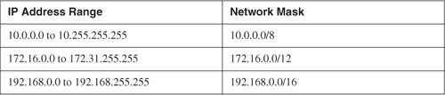
NAT enables organizations to use any IP address space as the internal network. A best practice is to use the address spaces that are reserved for private use (see RFC 1918, "Address Allocation for Private Internets"). Table 1-1 lists the private address ranges specified in RFC 1918.
Table 1-1. Private Address Ranges Specified in RFC 1918
NAT techniques come in various types. The most common are Port Address Translation (PAT) and Static NAT. PAT allows many devices on a network segment to be translated to one IP address by inspecting the Layer 4 information on the packet. Figure 1-3 illustrates how three different machines on the corporate network are translated to a single public address.
Figure 1-3. PAT

In Figure 1-3, the host with IP address 192.168.1.100 attempts to access the web server with IP address 209.165.200.230. The firewall translates the internal address to 209.165.200.226 using the source TCP port 1024 and mapping it to TCP port 1234. Notice that the destination port remains the same (port 80).
Stateful Firewalls
Stateful inspection firewalls track every connection passing through their interfaces by examining not only the packet header contents but also the application layer information within the payload. This is done to find out more about the transaction than just the source and destination addresses and ports. Typically, a stateful firewall monitors the state of the connection and maintains a table with the Layer 3 and Layer 4 information. More sophisticated firewalls perform upper-layer protocol analysis, also known as deep-packet inspection, which is discussed later in this chapter. The state of the connection details whether such connection has been established, closed, reset, or is being negotiated. These mechanisms offer protection for different types of network attacks.
Cisco IOS firewall, Cisco Adaptive Security Appliances (ASA), Cisco PIX firewalls, and the Cisco Firewall Services Module (FWSM) for the Cisco Catalyst 6500 series switches are examples of stateful firewalls. They also have other rich features such as deep packet inspection.
Note
For detailed deployment, configuration, and troubleshooting information, see the Cisco Press book titled Cisco ASA: All-in-One Firewall, IPS, and VPN Adaptive Security Appliance.
Deep Packet Inspection
Several applications require special handling of data packets when they pass through firewalls. These include applications and protocols that embed IP addressing information in the data payload of the packet or open secondary channels on dynamically assigned ports. Sophisticated firewalls and security appliances such as the Cisco ASA, Cisco PIX firewall, and Cisco IOS firewall offer application inspection mechanisms to handle the embedded addressing information to allow the previously mentioned applications and protocols to work. Using application inspection, these security appliances can identify the dynamic port assignments and allow data exchange on these ports during a specific connection.
With deep packet inspection, firewalls can look at specific Layer 7 payloads to protect against security threats. For example, you can configure a Cisco ASA or a Cisco PIX firewall running version 7.0 or later to not allow peer-to-peer (P2P) applications to be transferred over HTTP tunnels. You can also configure these devices to deny specific FTP commands, HTTP content types, and other application protocols.
Note
The Cisco ASA and Cisco PIX firewall running version 7.0 or later provide a Modular Policy Framework (MPF) that allows a consistent and flexible way to configure application inspection and other features in a manner similar to the Cisco IOS Software Modular quality of service (QoS) command-line interface (CLI).
Demilitarized Zones
Numerous firewalls can configure network segments (or zones), usually called demilitarized zones (DMZ). These zones provide security to the systems that reside within them with different security levels and policies between them. DMZs have a couple of purposes: as segments on which a web server farm resides or as extranet connections to a business partner. Figure 1-4 shows a firewall (a Cisco ASA in this case) with two DMZs.
Figure 1-4. DMZ Example
In Figure 1-4, DMZ 1 hosts web servers that are accessible by internal and Internet hosts. The Cisco ASA controls access from an extranet business partner connection on DMZ 2.
Note
In large organizations, you can deploy multiple firewalls in different segments and DMZs.
Personal Firewalls
Personal firewalls are popular software applications that you can install on end-user machines or servers to protect them from external security threats and intrusions. The term personal firewall typically applies to basic software that can control Layer 3 and Layer 4 access to client machines. Today, sophisticated software is available that not only provides basic personal firewall features but also protects the system based on the behavior of the applications installed on such systems. An example of this type of software is the Cisco Security Agent (CSA). CSA provides several features that offer more robust security than a traditional personal firewall. The following are CSA-rich security features:
• Host intrusion prevention
• Protection against spyware
• Protection against buffer overflow attacks
• Distributed host firewall features
• Malicious mobile code protection
• Operating system integrity assurance
• Application inventory
• Extensive audit and logging capabilities
Note
Host intrusion prevention systems (HIPS) are detailed and described later in this chapter.
Virtual Private Networks (VPN)
Organizations of all sizes deploy VPNs to provide data integrity, authentication, and data encryption to assure confidentiality of the packets sent over an unprotected network or the Internet. VPNs are designed to avoid the cost of unnecessary leased lines.
Many different protocols are used for VPN implementations, including these:
• Point-to-Point Tunneling Protocol (PPTP)
• Layer 2 Forwarding (L2F) Protocol
• Layer 2 Tunneling Protocol (L2TP)
• Generic Routing Encapsulation (GRE) Protocol
• Multiprotocol Label Switching (MPLS) VPN
• Internet Protocol Security (IPsec)
• Secure Socket Layer (SSL)
Note
PPTP, L2F, L2TP, GRE, and MPLS VPNs do not provide data integrity, authentication, and data encryption. On the other hand, you can combine L2TP, GRE, and MPLS with IPsec to provide these benefits. Many organizations use IPsec as their preferred protocol because it supports all three features described earlier (data integrity, authentication, and data encryption).
VPN implementations can be categorized into two distinct groups:
• Site-to-site VPNs: Allow organizations to establish VPN tunnels between two or more sites so that they can communicate over a shared medium such as the Internet. Many organizations use IPsec, GRE, and MPLS VPN as site-to-site VPN protocols.
• Remote-access VPNs: Allow users to work from remote locations such as their homes, hotels, and other premises as if they were directly connected to their corporate network.
Figure 1-5 illustrates a site-to-site IPsec tunnel between two sites (corporate headquarters and a branch office), as well as a remote access VPN from a telecommuter working from home.
Figure 1-5. Site-to-Site and Remote Access VPN Example
Cisco ASAs are used in the example shown in Figure 1-5. The Cisco ASA integrates many IPsec and SSL VPN features with firewall capabilities. Other Cisco products that support VPN features are as follows:
• Cisco VPN 3000 series concentrators
• Cisco IOS routers
• Cisco PIX firewalls
• Cisco Catalyst 6500 switches and Cisco 7600 series routers WebVPN services module
• Cisco 7600 series/Catalyst 6500 series IPsec VPN shared port adapter
Note
The use and deployment of these devices are described in Chapter 2. You can also find information about these devices at the Cisco website at cisco.com/go/security.
Technical Overview of IPsec
IPsec uses the Internet Key Exchange (IKE) Protocol to negotiate and establish secured site-to-site or remote access VPN tunnels. IKE is a framework provided by the Internet Security Association and Key Management Protocol (ISAKMP) and parts of two other key management protocols, namely Oakley and Secure Key Exchange Mechanism (SKEME).
Note
IKE is defined in RFC 2409, "The Internet Key Exchange."
ISAKMP has two phases. Phase 1 is used to create a secure bidirectional communication channel between the IPsec peers. This channel is known as the ISAKMP Security Association (SA).
Phase 1
Within Phase 1 negotiation, several attributes are exchanged, including the following:
• Encryption algorithms
• Hashing algorithms
• Diffie-Hellman groups
• Authentication method
• Vendor-specific attributes
The following are the typical encryption algorithms:
• Data Encryption Standard (DES): 64 bits long
• Triple DES (3DES): 168 bits long
• Advanced Encryption Standard (AES): 128 bits long
• AES 192: 192 bits long
• AES 256: 256 bits long
Hashing algorithms include these:
• Secure Hash Algorithm (SHA)
• Message digest algorithm 5 (MD5)
The common authentication methods are preshared keys (where the peers agree on a shared secret) and digital certificates with the use of Public Key Infrastructure (PKI).
Note
Typically, small and medium-sized organizations use preshared keys as their authentication mechanism. Several large organizations use digital certificates for scalability, for centralized management, and for the use of additional security mechanisms.
You can establish a Phase 1 SA in two ways:
• Main mode
• Aggressive mode
In main mode, the IPsec peers complete a six-packet exchange in three round-trips to negotiate the ISAKMP SA, whereas aggressive mode completes the SA negotiation in three packet exchanges. Main mode provides identity protection if preshared keys are used. Aggressive mode only provides identity protection if digital certificates are used.
Note
Cisco products that support IPsec typically use main mode for site-to-site tunnels and aggressive mode for remote-access VPN tunnels. This is the default behavior when preshared keys are used as the authentication method.
Figure 1-6 illustrates the six-packet exchange in main mode negotiation.
Figure 1-6. Main Mode Negotiation

In Figure 1-6, two Cisco IOS Software routers are configured to terminate a site-to-site VPN tunnel between them. The router labeled as R1 is the initiator, and R2 is the responder. The following are the steps illustrated in Figure 1-6.
Step 1. R1 (the initiator) has two ISAKMP proposals configured. In the first packet, R1 sends its configured proposals to R2.
Step 2. R2 evaluates the received proposal. Because it has a proposal that matches the offer of the initiator, R2 sends the accepted proposal back to R1 in the second packet.
Step 3. Diffie-Hellman exchange and calculation is started. R1 sends the Key Exchange (KE) payload and a randomly generated value called a nonce.
Step 4. R2 receives the information and reverses the equation using the proposed Diffie-Hellman group/exchange to generate the SKEYID.
Step 5. R1 sends its identity information. The fifth packet is encrypted with the keying material derived from the SKEYID. The asterisk in Figure 1-6 is used to illustrate that this packet is encrypted.
Step 6. R2 validates the identity of R1, and R2 sends the identity information of R1. This packet is also encrypted.
Phase 2
Phase 2 is used to negotiate the IPsec SAs. This phase is also known as quick mode. The ISAKMP SA protects the IPsec SAs, because all payloads are encrypted except the ISAKMP header. Figure 1-7 illustrates the Phase 2 negotiation between the two routers that just completed Phase 1.
Figure 1-7. Phase 2 Negotiation

The following are the steps illustrated in Figure 1-7.
Step 1. R1 sends the identity information, IPsec SA proposal, nonce payload, and (optional) KE payload if Perfect Forward Secrecy (PFS) is used. PFS is used to provide additional Diffie-Hellman calculations.
Step 2. R2 evaluates the received proposal against its configured proposal and sends the accepted proposal back to R1 along with its identity information, nonce payload, and the optional KE payload.
Step 3. R1 evaluates the R2 proposal and sends a confirmation that the IPsec SAs have been successfully negotiated. This starts the data encryption process.
IPsec uses two different protocols to encapsulate the data over a VPN tunnel:
• Encapsulation Security Payload (ESP): IP Protocol 50
• Authentication Header (AH): IP Protocol 51
Note
ESP is defined in RFC 2406, "IP Encapsulating Security Payload (ESP)," and AH is defined in RFC 2402, "IP Authentication Header."
IPsec can use two modes with either AH or ESP:
• Transport mode: Protects upper-layer protocols, such as User Datagram Protocol (UDP) and TCP
• Tunnel mode: Protects the entire IP packet
Transport mode is used to encrypt and authenticate the data packets between the peers. A typical example of this is the use of GRE over an IPsec tunnel. Tunnel mode is used to encrypt and authenticate the IP packets when they are originated by the hosts connected behind the VPN device. Tunnel mode adds an additional IP header to the packet, as illustrated in Figure 1-8.
Figure 1-8. Tunnel and Transport Mode Example

Figure 1-8 demonstrates the major difference between transport and tunnel mode. It includes an example of an IP packet encapsulated in GRE and the difference when it is encrypted in transport mode and tunnel mode.
Note
Tunnel mode is the default mode in Cisco IPsec devices.
SSL VPNs
SSL-based VPNs are in high demand today. SSL is a matured protocol that has been in existence since the early 1990s. SSL is also referred to as Transport Layer Security (TLS). The Internet Engineering Task Force (IETF) created TLS to consolidate the different SSL vendor versions into a common and open standard.
One of the most popular features of SSL VPN is the ability to launch a browser like Microsoft Internet Explorer and Firefox and simply connect to the address of the VPN device. In most implementations, a clientless solution is possible. Users can access corporate intranet sites, portals, and e-mail from almost anywhere (even from an airport kiosk). Because most people allow SSL (TCP port 443) over their firewalls, it is unnecessary to open additional ports.
For more elaborate access to corporate resources, a lite-SSL client can be installed on a user machine. Cisco supports both clientless SSL VPN (WebVPN) and a lite-client. The SSL VPN Client (SVC) gives remote users the benefits of an IPsec VPN client without the need for network administrators to install and configure IPsec VPN clients on remote computers. The SVC uses the SSL encryption that is already present on the remote computer to authenticate to the VPN device. Cisco supports SSL VPN on the following products:
• Cisco ASA
• Cisco VPN 3000 series concentrators
• Cisco IOS routers
• Cisco WebVPN Services Module
Intrusion Detection Systems (IDS) and Intrusion Prevention Systems (IPS)
This section includes an overview of intrusion detection systems (IDS) and intrusion prevention systems (IPS). IDSs are devices that detect (in promiscuous mode) attempts from an attacker to gain unauthorized access to a network or a host to create performance degradation or to steal information. They also detect distributed denial of service (DDoS) attacks, worms, and virus outbreaks. IPS devices are capable of detecting all these security threats; however, they are also able to drop noncompliant packets inline. Packets that do not comply with security policies will not pass to the protected network. This is the major difference between IDS and IPS systems. Figure 1-9 shows how an IDS device is configured to promiscuously detect security threats.
Figure 1-9. IDS Example

In Figure 1-9, an attacker sends a malicious packet to a web server. The IDS device analyzes the packet and sends an alert to a monitoring system (CS-MARS in this example). The malicious packet makes it to the web server. In contrast, Figure 1-10 shows how an IPS device is placed inline and drops the noncompliant packet, while sending an alert to the monitoring system.
Figure 1-10. IPS Example
Two different types of IPS exist:
• Network-based (NIPS)
• Host-based (HIPS)
Note
Examples of NIPSs are the Cisco IPS 4200 sensors, the Catalyst 6500 IPS Module, and the Cisco ASA with the Advanced Inspection and Prevention Security Services Module (AIP-SSM). An example of a host-based IPS is CSA. More details and recommendation on how to protect your network with IPS devices are covered in Chapter 2.
Network-based IDS and IPS use several detection methodologies, such as the following:
• Pattern matching and stateful pattern-matching recognition
Pattern Matching
Pattern matching is a methodology in which the intrusion detection device searches for a fixed sequence of bytes within the packets traversing the network. Generally, the pattern is aligned with a packet that is related to a respective service or, in particular, associated with a source and destination port. This approach reduces the amount of inspection made on every packet. However, it is limited to services and protocols that are associated with well-defined ports. Protocols that do not use Layer 4 port information are not categorized. This tactic uses the concept of signatures. A signature is a set of conditions that point out some type of intrusion occurrence. For example, if a specific TCP packet has a destination port of 1234, and its payload contains the string "ff11ff22," an alert is triggered to detect such a string. Alternatively, the signature might include an explicit starting point and endpoint for inspection within the specific packet.
Tip
One of the main disadvantages of pattern matching is that it can lead to a considerably high rate of false positives. False positives are alerts that do not represent a genuine malicious activity. In contrast, any alterations to the attack can lead to overlooked events of real attacks, which are normally referred to as false negatives.
A more refined method was created to address some of these limitations. This methodology is called stateful pattern-matching recognition, which dictates that systems performing this type of signature analysis must consider the chronological order of packets in a TCP stream. In particular, they should judge and maintain a stateful inspection of such packets and flows.
Protocol Analysis
Protocol analysis (or protocol decode-base signatures) is referred to as the extension to stateful pattern recognition. A network-based IDS accomplishes protocol analysis by decoding all protocol or client-server conversations. The NIDS identifies the elements of the protocol and analyzes them while looking for an infringement. Some intrusion detection systems look at explicit protocol fields within the inspected packets. Others require more sophisticated techniques, such as examination of the length of a field within the protocol or the number of arguments. For example, in Simple Mail Transfer Protocol (SMTP), the device may look at specific commands and fields such as HELO, MAIL, RCPT, DATA, RSET, NOOP, and QUIT. This technique diminishes the possibility of encountering false positives if the protocol being analyzed is properly defined and enforced. On the other hand, the system can alert numerous false positives if the protocol definition is ambiguous or tolerates flexibility in its implementation.
Heuristic-Based Analysis
A different approach to network intrusion detection is to perform heuristic-based analysis. Heuristic scanning uses algorithmic logic from statistical analysis of the traffic passing through the network. Its tasks are CPU and resource intensive. This is an important consideration while planning your deployment. Heuristic-based algorithms may require fine tuning to adapt to network traffic and minimize the possibility of false positives. For example, a system signature can generate an alarm if a range of ports is scanned on a particular host or network. The signature can also be orchestrated to restrict itself from specific types of packets (for example, TCP SYN packets).
Anomaly-Based Analysis
A different practice keeps track of network traffic that diverges from "normal" behavioral patterns. This practice is called anomaly-based analysis. You must define what is considered to be normal behavior. Systems and applications whose behavior can be easily considered normal could be classified as heuristic-based systems. However, sometimes it is challenging to classify a specific behavior as normal or abnormal based on different factors. These factors include negotiated protocols and ports, specific application changes, and changes in the architecture of the network.
A variation of this type of analysis is profile-based detection. This allows systems to orchestrate their alarms on alterations in the way that other systems or end users interrelate on the network.
Another kind of anomaly-based detection is protocol-based detection. This scheme is related to, but not to be confused with, the protocol-decode method. The protocol-based detection technique depends on well-defined protocols because it detects as an anomaly any unpredicted value or configuration within a field in the respective protocol.
More sophisticated anomaly detection techniques exist. These are described in the next section.
Anomaly Detection Systems
IDS and IPS provide excellent application layer attack-detection capabilities. However, they do have a weakness—they cannot detect DDoS attacks using valid packets. IDS and IPS devices are optimized for signature-based application layer attack detection. Most of them do not provide day-zero protection.
Note
Although some IPS devices do offer anomaly-based capabilities, which are required to detect such attacks, they require extensive manual tuning by experts and do not identify the specific attack flows. Cisco IPS Software Version 6.x and later support more sophisticated anomaly detection techniques. More information can be obtained at http://www.cisco.com/go/ips.
You can use anomaly-based detection systems to mitigate DDoS attacks and day-zero outbreaks. Typically, an anomaly detection system monitors network traffic and alerts or reacts to any sudden increase in traffic and any other anomalies. Cisco delivers a complete DDoS protection solution based on the principles of detection, diversion, verification, and forwarding to help ensure total protection. Examples of sophisticated anomaly detection systems are the Cisco Traffic Anomaly Detectors and the Cisco Guard DDoS Mitigation Appliances.
You can also use NetFlow as an anomaly detection tool. NetFlow is a Cisco technology that supports monitoring of network traffic. The beauty of NetFlow is that it is free with any licensed Cisco IOS image.
Note
Refer to the Cisco feature navigator to find out in what Cisco IOS image NetFlow is supported. You can access this tool at http://tools.cisco.com/ITDIT/CFN/jsp/index.jsp.
NetFlow uses a UDP-based protocol to periodically report on flows seen by the Cisco IOS device. A flow is a Layer 7 concept that consists of session setup, data transfer, and session teardown. You can also integrate NetFlow with Cisco Secure Monitoring and Response System (CS-MARS). When NetFlow is integrated with CS-MARS, you can take advantage of anomaly detection using statistical profiling, which can pinpoint day-zero attacks such as worm outbreaks.
Note
Chapter 3, "Identifying and Classifying Security Threats," provides more information on how to identify security threats using anomaly detection systems.
Authentication, Authorization, and Accounting (AAA) and Identity Management
AAA offers different solutions that provide access control to network resources. This section introduces AAA and identity management concepts.
Authentication is the process of validating users based on their identity and predetermined credentials, such as passwords and other mechanisms like digital certificates. Authentication is widely used in many different applications, from a user attempting to log in to the network, web server, and wireless access point to an administrator logging in to a firewall, router, or any other network device to successfully configure the former.
The authentication concept is simple. Before you can withdraw money from your favorite bank, the teller asks for your credentials (driver's license, account number, and so on). Similarly, networking devices, servers, and other systems can ask you for credentials such as passwords and digital certificates for you to obtain access to the network or any other resources.
Authorization is the method by which a network device assembles a set of attributes that regulates what tasks the user is authorized to perform. These attributes are measured against a user database. The results are returned to the network device to determine the user qualifications and restrictions.
Accounting is the process of gathering and sending user information to an AAA server used to track login times (when the user logged in and logged off) and the services that users access. This information can be used for billing, auditing, and reporting purposes.
Two common AAA protocols are used in networking today:
• Remote Authentication Dial-in User Service (RADIUS)
• Terminal Access Controller Access Control System Plus (TACACS+)
RADIUS
RADIUS is a widely implemented authentication standard protocol that is defined in RFC 2865. RADIUS operates in a client/server model. A RADIUS client is usually referred to as a network access server (NAS). A NAS is responsible for passing user information to the RADIUS server. Network devices such as routers, firewalls, and switches can act as a NAS and authenticate users based on the RADIUS server response.
Cisco develops and sells a RADIUS and TACACS+ server called Cisco Secure Access Control Server (ACS). Cisco Secure ACS supports a rich set of AAA features and applications. These advanced features include the following:
• Lightweight Directory Access Protocol (LDAP) and Open Database Connectivity (ODBC) user authentication support
• Flexible 802.1X authentication type support, including Extensible Authentication Protocol Transport Layer Security (EAP-TLS), Protected EAP (PEAP), EAP-Flexible Authentication via Secure Tunneling (EAP-FAST), and EAP-Message Digest Algorithm 5 (EAP-MD5) and other protocols
• Timed-based access
• Downloadable for any Layer 3 device, including Cisco routers, Cisco PIX firewalls, Cisco ASA, and Cisco VPNs
• Device command authorization
• Advanced database synchronization and replication features
• Network access restrictions
• Detailed reporting and accounting capabilities
• User and device group profiles
Note
For more information about Cisco Secure ACS, go to http://www.cisco.com/go/acs.
Figure 1-11 illustrates the basic RADIUS authentication process.
Figure 1-11. RADIUS Authentication Process
The following are the steps illustrated in Figure 1-11.
Step 1. An access-request is sent from the AAA client (a router in this example) to the RADIUS server.
Step 2. If the user is successfully authenticated, an access-accept is sent from the RADIUS server to the AAA client. This access-accept packet can contain authorization attributes if authorization is enabled. If the user is not successfully authenticated, an access-reject is sent instead.
Step 3. An accounting request (start) message is sent from the AAA client (if configured to do accounting) to the RADIUS server.
Step 4. If the RADIUS server is configured for accounting, it replies with an acknowledgement.
Step 5. At the end of the user session, an accounting request (stop) message is sent from the AAA client (if configured to do accounting) to the RADIUS server.
Step 6. If the RADIUS server is configured for accounting, it replies with an acknowledgement.
This exchange is done over UDP. Older implementations of RADIUS use UDP port 1645 for authentication and UDP port 1646 for accounting. The newer implementations use UDP port 1812 for authentication and UDP port 1813 for accounting.
Note
A RADIUS server can also send IETF or vendor-specific attributes to the AAA client depending on the implementation and services used. These attributes can contain information such as an IP address to assign the client and authorization information. RADIUS servers combine authentication and authorization phases into a single request and response communication cycle.
TACACS+
TACACS+ is an AAA security protocol developed by Cisco that provides centralized validation of users who are attempting to gain access to network access devices. The TACACS+ protocol offers support for separate and modular AAA facilities. The primary goal of the TACACS+ protocol is to supply complete AAA support for managing multiple network devices. Unlike RADIUS, TACACS+ uses TCP port 49 by default instead of UDP for its communications. However, it can allow vendors to use UDP. Cisco products use the TCP version for their TACACS+ implementation. The TACACS+ authentication concept is similar to RADIUS. The NAS sends an authentication request to the TACACS+ server, which in turn sends any of the following messages back to the NAS:
• ACCEPT: The user has been successfully authenticated and the requested service will be allowed. If authorization is required, the authorization process will begin at this point.
• REJECT: User authentication was denied. The user may be prompted to retry authentication depending on the TACACS+ server and NAS.
• ERROR: An error took place during authentication. This can be happen because of network connectivity problems or a configuration error.
• CONTINUE: The user is prompted to provide further authentication information.
After the authentication process is complete, if authorization is required, the TACACS+ server proceeds with the authorization phase. The user must first successfully be authenticated before proceeding to TACACS+ authorization.
As an industry standard, RADIUS is a more widely deployed protocol than TACACS+.
Identity Management Concepts
Many identity management solutions and systems automatically manage user access privileges within an organization. Today, enterprises are under great pressure to increase security and meet regulatory and governance requirements, resulting in greater urgency to deploy identity management solutions. Role-based authentication is a key concept of identity management. It helps to answer the critical compliance questions of "Who has access to what, when, how, and why?" For example, with role-based authentication, a contractor logging in to the network can access only the resources he should have access to. Based on his role and authorization parameters, he can be restricted from accessing critical financial information.
IEEE 802.1X is a standard that defines the encapsulation methodologies for the transport of EAP over any PPP or Ethernet media. 802.1X allows you to enforce port-based network access control when devices attempt to access the network. The 802.1x standard has three components:
• Supplicant
• Authenticator
• Authentication server
The supplicant is the software that resides on the end-user machine. The authenticator (typically a switch or wireless access point) relays the EAP information from the supplicant to an authentication server via the RADIUS protocol.
Cisco has a comprehensive identity management solution based on 802.1x called Identity-Based Networking Services (IBNS). IBNS is an integrated solution that uses Cisco products which offer authentication, access control, and user policies to secure network connectivity and resources. These products include the following:
• Cisco Catalyst family of switches
• Wireless LAN access points and controllers
• Cisco Secure ACS
• Cisco Secure Services Client
Additional and optional components include X.509 public key infrastructure (PKI) certificate architecture.
Note
You can find detailed IBNS information including configuration and deployment guidelines at http://www.cisco.com/go/ibns.
Information on how the IBNS and 802.1x solution is integrated into Cisco NAC is covered in the following section.
Network Admission Control
Network Admission Control is a multipart solution that validates the security posture of an endpoint system before entering the network. With NAC, you can also define what resources the endpoint has access to, based on the results of its security posture. NAC is a key part of the Cisco Self-Defending Network Initiative (SDNI). The SDNI mission is to dramatically improve the ability of the network to identify, prevent, and adapt to threats. NAC comes in two flavors:
• NAC Appliance: Based on the Cisco Clean Access (CCA)
• NAC Framework: A Cisco-sponsored industry wide initiative
NAC Appliance
NAC Appliance or Cisco Clean Access (CCA) enables an organization to enforce security policies by blocking, quarantining, and performing remediation of noncompliant systems. Remediation occurs at the discretion of the administrator. The policies and requirements enforced by NAC Appliance include checks for latest antivirus software, operating system (OS) patches and security patches. NAC Appliance can also perform vulnerability scanning on the end-user machine in addition to role-based authentication on users attempting to connect to the network. The NAC Appliance solution can restrict what resources these users can access, based on their role. All these policies and configurations are done in the Clean Access Manager (CAM).
The Cisco NAC Appliance has three major components:
• Clean Access Server (CAS): Acts as a network control device
• Clean Access Manager (CAM): Manages one or more servers
• Clean Access Agent (optional): Serves as an end-point lightweight client for device-based registry scans in unmanaged environments
The CAM can manage up to 40 CASs depending on the license and is licensed based on the number of CASs it supports. The CAS supports up to 1500 users depending on the license that is installed. The CAS license is based on the concurrent number of clients/users it supports.
Note
For more information about the NAC Appliance licensing, visit http://www.cisco.com/en/US/products/ps6128/prod_pre_installation_guide09186a008073136b.html.
CAS can be deployed in in-band (IB) or out-of-band (OOB) modes. CASs can pass traffic in one of two ways:
• Bridged mode: Typically called Virtual Gateway mode
• Routed mode: In Real IP Gateway or NAT Gateway configurations
Note
You can configure the CASs in either mode, but only in one mode at a time. For example, if you configure a CAS in Virtual Gateway configuration, you cannot also configure it as a Real IP Gateway. This is because the mode selection affects the logical traffic path.
Figure 1-12 illustrates a CAS configured in Virtual Gateway mode. In this example, the unprotected (untrusted) segment is VLAN 110 and the protected (trusted) network is VLAN 10.
Figure 1-12. CAS in Virtual Gateway Mode
The client workstation has an IP address on the same subnet/range of the trusted network (10.10.10.0/24). In Virtual Gateway mode, the CAS acts as a bridge. DHCP client routes point directly to network devices on the protected network.
Figure 1-13 shows a CAS configured in Real IP mode.
Figure 1-13. CAS in Real IP Mode

In Real IP mode, the CAS acts as a Layer 3 router. In this example, the CAS trusted and untrusted interfaces are in different subnets. The trusted subnet is 10.10.10.0/24, and the untrusted subnet is 192.168.10.0/24. In Real IP mode, DHCP clients usually point to the CAS to obtain their IP addresses and other DHCP information. It is a best practice to assign a 30-bit address to the DHCP clients. This enables you to isolate machines that can be infected with a virus and block them from infecting other machines in the network.
Note
The CAS can optionally be configured to translate the trusted network.
In summary, the NAC Appliance can operate in in-band (IB) or out-of-band (OOB) modes:
• IB Virtual Gateway (L2 transparent bridge mode): Acts as a bridge between the untrusted and trusted networks.
• IB Real-IP Gateway: Operates as the default gateway for the untrusted network.
• IB NAT Gateway (used for testing only): Acts as an IP router/default gateway and translates (NAT) the untrusted network.
• OOB Virtual Gateway (L2 transparent bridge mode): Initially acts as a virtual gateway during authentication and certification, before the user is switched out-of-band.
• OOB Real-IP Gateway: Initially acts as a Real-IP gateway during authentication and certification, before the user is switched out-of-band. (That is, the user is connected directly to the access network.)
• OOB NAT Gateway (used for testing only): Acts as a NAT gateway during authentication and certification, before the user is switched out-of-band.
You can deploy CASs in three physical deployment modes:
• Edge deployment
• Centralized deployment
• Centralized edge deployment
Note
The physical deployment method does not affect whether a CAS is in Layer 2 (bridged), Layer 3 (routed), IB, or OOB mode.
Figure 1-14 illustrates a NAC Appliance edge deployment. In this example, the untrusted interface is connected to VLAN 110, and the trusted interface is connected to VLAN 10. The CAM resides on the management segment (VLAN 123). In this example, the CAS is configured in Virtual Gateway mode and is mapping VLAN 10 with VLAN 110.
Figure 1-14. NAC Appliance Edge Deployment
Figure 1-15 illustrates a NAC Appliance centralized deployment. In this example, both the CAS trusted and untrusted interfaces are physically connected to the central switch (SW1). The switch is configured with several VLANs. The untrusted VLAN is VLAN 110, the trusted VLAN is VLAN 10, and the management VLAN is VLAN 123.
Figure 1-15. NAC Appliance Centralized Deployment
The NAC Appliance centralized deployments are the most common deployment option, because they are better suited for scalability in medium-to-large environments. In this example, the CAS is logically, not physically, in-line.
The NAC Appliance solution supports failover for high-availability. You can deploy the CAM and CAS in failover pairs, as illustrated in Figure 1-16.
Figure 1-16. NAC Appliance High Availability
The example shown in Figure 1-16 includes two CAMs (CAM-1 and CAM-2). CAM-1 is the primary (active) manager, and CAM-2 is configured in standby mode. If CAM-1 fails, CAM-2 takes over. In Figure 1-16, a total of four CASs are deployed: two active and two in standby. For scalability reasons, CAS-1 is performing posture validation for clients on the first three untrusted VLANs (VLAN 110, 111, and 112). The CAS-2 is enforcing posture validation on the last three untrusted VLANs (VLAN 113, 114, and 115). If CAS-1 fails, CAS-3 will take over, and if CAS-2 fails, CAS-4 will take over.
Note
Active-active failover configuration is not currently supported.
In most scenarios, a combination of different CAS deployment strategies are used. These are examples of the most common deployment types:
• Layer 2 IB for wireless environments
• Layer 3 or Layer 2 IB for remote access VPN
• Layer 2 OOB for campus LAN deployments
Note
This chapter introduces the basics of the NAC Appliance solution. For information about the configuration and troubleshooting of NAC Appliance, go to http://www.cisco.com/go/cca. Chapter 2 demonstrates how to deploy NAC Appliance to provide posture validations while preparing your network and infrastructure to self-protect against security threats.
NAC Framework
NAC Framework is a Cisco-led industry initiative to provide posture validation using embedded software in Cisco network access devices (NAD) such as routers, switches, VPN concentrators, Cisco ASA, wireless access points, and others. Many vendors are part of the Cisco NAC program. These Cisco partners include antivirus software vendors, remediation and patch management companies, identity software manufacturers, and others.
Note
To obtain the latest list of NAC program vendors/partners, go to http://www.cisco.com/go/nac and click on NAC program.
Similar to NAC Appliance, NAC Framework has three basic components:
• NAC Agent
• NAD
• Policy Server (Cisco Secure ACS or NAC Manager)
Optionally, you can use other vendor products such as external policy servers, remediation servers, and audit servers to provide more comprehensive admission control features. The NADs enforce policies configured in a centralized manager, while relaying the security credentials/information presented by the end-host NAC Agent. NAC Framework supports four different mechanisms when performing security posture validation on end-host machines:
• NAC Layer 3 IP: Uses EAP over UDP (EoU) and is typically deployed in Cisco IOS routers, Cisco ASA, and VPN 3000 concentrators.
• NAC Layer 2 IP: Uses EoU and is typically deployed in Cisco Catalyst switches. Address Resolution Protocol (ARP) and DHCP are the trigger mechanisms.
• NAC Layer 2 802.1x: Combines the traditional IBNS identity features and services with in-depth security posture validation.
The basic diagram shown in Figure 1-17 illustrates the NAC Framework from a high-level view.
Figure 1-17. NAC Framework High-Level Overview
The following steps are illustrated in Figure 1-17:
Step 1. The NAD (a switch in this example) challenges the end-host to present its credentials. This is done via EoU or EAP over 802.1x.
Step 2. The NAD forwards the end-host credentials to the NAC Manager (Cisco Secure ACS server in this example) using the EAP protocol over RADIUS.
Step 3. Optionally, the Cisco Secure ACS forwards user or machine credentials to an external vendor server. This server can be an antivirus vendor server, authentication server, or any other external policy server. The vendor server replies to the Cisco Secure ACS with a token, based on the posture results for the end-host that is attempting to connect to the network.
Step 4. The Cisco Secure ACS receives the token or checks its internal policies.
Step 5. The Cisco Secure ACS sends the posture information to the NAD. Subsequently, the NAD enforces policies based on the posture of the end-host device.
Note
The NAD periodically polls the end-hosts to determine if a change has been made in their posture. The NAC Agent alerts the NAD of any changes on the client machine. The NAD uses this information to issue full revalidation and posture assessment. This mechanism prevents hosts from being validated but not checked if their security posture has changed after they have been granted access to the network.
NAC Agentless Hosts (NAH) are devices on which the Cisco NAC Agent has not been installed. These devices can be printers, IP Phones, scanners, and other systems such as contractor and guest workstations. If a device does not have the NAC Agent, it cannot respond to the EoU or 802.1x request from the NAD. Separate policies can be configured on the NAD to exclude the NAH MAC or IP address, or a range of addresses. In addition, a global policy can be configured on Cisco Secure ACS.
Cisco developed a protocol called Generic Authorization Message Exchange (GAME). Third-party audit servers use this protocol to communicate with Cisco Secure ACS when performing elaborate scans and audits on NAC nonresponsive hosts. An example of an audit server vendor is Qualys. Cisco Secure ACS is responsible for triggering the audit process for nonresponsive hosts with the audit server. Audit servers can scan the nonresponsive device for known threats and vulnerabilities to further determine their security posture.
Note
For more information about the Cisco-Qualys NAC solution, go to http://www.cisco.com/web/partners/downloads/partner/WWChannels/programs/nac_qualys_sol_guide.pdf or to the Qualys website at http://www.qualys.com/products/qgent/integrations/nac/.
It is recommended that you use an event correlation and reporting system, such as CS-MARS, in conjunction with NAC. The process of collecting, correlating, troubleshooting, and trending NAC event information enables you to make necessary real-time corrections and ongoing improvements to the security posture of your end-host devices. This subsequently decreases the risk of known and unknown security threats in your organization.
Note
This chapter introduces the basics of the NAC Framework solution. For information about the detailed deployment, configuration, and troubleshooting, refer to the Cisco Press books titled Cisco Network Admission Control, Volume I: NAC Framework Architecture and Design and Cisco Network Admission Control, Volume II: NAC Deployment and Troubleshooting.
Chapter 2 demonstrates how to deploy NAC Framework to provide posture validations while preparing your network and infrastructure to self-protect against security threats.
Routing Mechanisms as Security Tools
Many people do not realize that routing is one of the most powerful security tools available. Several routing techniques help identify, classify, and mitigate security threats. Examples include remotely triggered black holes (RTBH) and sinkholes.
RTBH is a filtering technique that provides the ability to drop malicious traffic before it penetrates your network. Historically, RTBH has been a tool that many service providers have used to mitigate DDoS attacks. Many other organizations are now adopting RTBH.
In technical terms, a typical RTBH deployment requires running internal Border Gateway Protocol (iBGP) at the access and choke points and configuring a separate router strategically placed in the network to act as a trigger. This triggering router injects iBGP updates to the edge, causing the specified traffic to be sent to a null0 interface and subsequently be dropped. RTBH is highly scalable; therefore, it is primarily designed to mitigate against DDoS and worm outbreaks.
Note
Chapter 2 describes RTBH benefits, operational gains, deployment considerations, and sample router configurations.
A sinkhole, in some cases, is just a router used to redirect malicious traffic to a single IP address where it can be scrutinized in greater detail. In other cases, it is just a segment (place or interface) within the network where this traffic is sent. Service providers initially implemented this technique to identify hosts where an attack or worm traffic was being generated. As with RTBH, enterprises now apply sinkholes. Initially, configuring a sinkhole router assisted in detecting infected devices or attackers when network intrusion detection or prevention systems were not available or when there were other architectural constraints. Today, IDSs are being integrated with sinkholes to better identify and classify these threats, consequently increasing infrastructure protection.
How do sinkhole routers work? A sinkhole router advertises IP addresses/networks not yet allocated by the Internet Assigned Numbers Authority (IANA). These addresses are referred to as bogon and dark IP addresses.
Note
You can find detailed information about bogon addresses at http://www.iana.org.
Some worms and attackers accidentally attempt to exploit these bogon addresses, which are advertised only locally. When the sinkhole router receives this traffic, it can log and discard it. These logs provide a list of infected hosts or attackers.
Tip
In enterprise environments, it is important to monitor dark IP address space instead of only bogon address space. In the future, you may see worms coded to ignore bogon addresses to avoid detection.
Figure 1-18 shows how to deploy a sinkhole router within an enterprise network.
Figure 1-18. Sinkhole Deployment Example
In Figure 1-18, the host on the left is infected with a worm and is attacking and attempting to compromise the user machines. The traffic destined for both bogon addresses and the dark IP address space are inspected by the sinkhole alerting the administrator of this anomaly. You can integrate elaborate tools with sinkholes to easily detect these types of threats.
Note
Chapter 2 details the use of sinkholes as part of the preparation phase of the six-step methodology of incident readiness and response.
Summary
This chapter introduced a range of security technologies and products to help you understand the best practices and methodologies you will learn in later chapters. It presented an overview of how to place firewalls to provide perimeter security and network segmentation while enforcing configured policies. This chapter also gave an overview of VPN technologies and protocols. It covered IPsec and its related protocols in detail to enhance the learning. It also presented an overview of SSL VPNs and their uses.
IDS and IPS systems can aid in identifying and classifying security threats within your network. This chapter covered an overview and the differences between IDS and IPS technologies. Beyond IDS and IPS, anomaly detection systems help you react to day-zero outbreaks. This chapter also helps you understand the concept and technologies of anomaly detection systems.
AAA offers different solutions that provide access control to network resources. This chapter introduced AAA and identity management concepts. It included an overview of the Cisco Network Admission Control solutions used to enforce security policy compliance on all devices seeking to access network computing resources, thereby limiting damage from emerging security threats.
You can use routing techniques as security tools. This chapter gave you an example of different routing techniques such as RTBH and sinkholes that you can use to increase the security of the network and to react to new threats.