Chapter 7. Proactive Security Framework
This chapter covers the following topics:
• Instrumentation and Management
• Isolation and Virtualization
Many network security frameworks are in the marketplace and most of them have the common goal of providing a methodical and efficient approach to network security. No framework is perfect, you should choose an approach that can help reduce the time, cost, and resources needed to plan and deploy your security strategy. This chapter highlights best practices and benefits of different security frameworks.
A framework can help you establish a view of your entire security landscape, identify potential capability gaps, and prioritize initiatives for improvement.
The Security Assessment, Validation, and Execution (SAVE) framework, formerly known as the Cisco Operational Process Model (COPM), is a security framework that enables visibility and control for end-to-end security. Cisco initially designed SAVE for the Internet service provider (ISP) part of the Next-Generation Network (NGN) initiative. However, you can also apply its practices to enterprises.
Today, malicious traffic within ISPs is spreading faster than before because attack tools are becoming more sophisticated and easier to find. ISPs have witnessed a transformation in the community that engages in cybercrime activities for financial reward, otherwise known as the miscreant economy. The principles introduced by SAVE allow ISPs and other organizations to defend against these threats while maintaining control and visibility of their networks.
SAVE defines network security in six major categories or "pillars." Figure 7-1 illustrates the different categories within the SAVE framework.
Figure 7-1. SAVE Categories Illustrated
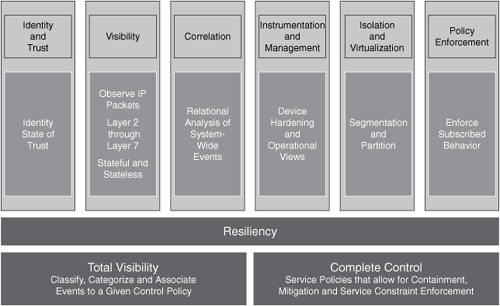
The six pillars in SAVE are as follows:
• Instrumentation and management
• Isolation and virtualization
SAVE Versus ITU-T X.805
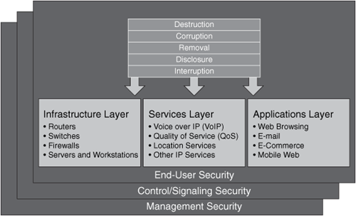
There is a security methodology created by the Lucent consulting practice called ITU-T X.805, "Security Architecture for Systems Providing End-to-End Communications." ITU-T X.805 defines a threat model that includes five categories:
• Destruction
• Corruption
• Removal
• Disclosure
• Interruption
ITU-T X.805 defines three security layers:
• Infrastructure layer
• Services layer
• Applications layer
Figure 7-2. ITU-T X.805 Security Layers

The ITU-T X.805 infrastructure layer includes all infrastructure devices, including:
• Routers
• Switches
• Firewalls
• Servers
• End-user workstations
The services layer includes services such as the following:
• Voice over IP (VoIP)
• Quality of service (QoS)
• Location services
• Other IP services
The applications layer includes all Layer 7 applications that run on the network infrastructure. Each layer has unique threats, vulnerabilities, and ways to mitigate them. X.805 also has three security planes:
• End-user plane
• Control/Signaling plane
• Management plane
These security planes are illustrated in Figure 7-3.
Figure 7-3. ITU-T X.805 Planes
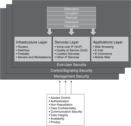
X.805 also includes eight security dimensions that apply to each security layer and plane. The following are these dimensions:
• Access control: Firewall policies and access control lists (ACL).
• Authentication: Public key infrastructure (PKI), shared secrets, and one-time-passwords.
• Nonrepudiation: Syslogs and digital signatures.
• Data confidentiality: This confidentiality occurs through the use of encryption.
• Communication security: Transport mechanisms such as IP Security (IPsec) and Secure Socket Layer (SSL) virtual private networks (VPN), in addition to Layer 2 Tunneling Protocol (L2TP) tunnels.
• Data integrity: Hashing with message digest algorithm 5 (MD5) and Secure Hash Algorithm (SHA).
• Availability: Examples include redundancy with Hot Standby Router Protocol (HSRP) or Virtual Router Redundancy Protocol (VRRP).
• Privacy: Encryption and Network Address Translation (NAT).
The eight security dimensions are illustrated in Figure 7-4.
Figure 7-4. ITU-T X.805 Security Dimensions
Confused yet? X.805 is an overcomplicated approach. Cisco has tried to evolve it to make it more practical to use; however, X.805 is not a true end-to-end security framework and is even potentially harmful in the market and in standards.
SAVE introduces a roles-based approach for security assessment in a simple manner. Each device on the network serves a purpose and has a role; subsequently, you should configure each device accordingly. SAVE defines five different planes:
• Management plane: Distributed and modular network management environment.
• Control plane: Includes routing control. This is often a target because the control plane depends on direct CPU cycles.
• User/Data plane: Receives, processes, and transmits network data among all network elements.
• Services plane: Layer 7 application flow built on the foundation of the other layers.
• Policies: The business requirements. Cisco calls policies the business glue for the network. Policies and procedures are part of this section, and they apply to all the planes in this list.
These planes are illustrated in Figure 7-5.
Figure 7-5. Planes in SAVE

SAVE also presents security in two different perspectives:
• Operational (reactive) security
• Proactive security
This is illustrated in Figure 7-6.
Figure 7-6. Operational and Proactive Security
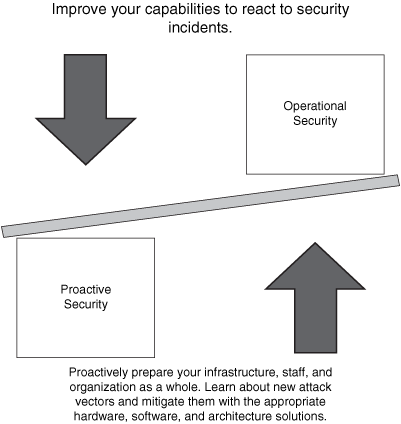
You should have a balance between proactive and reactive security approaches. Prepare your network, staff, and organization as a whole to better identify, classify, trace back, and react to security incidents. In addition, proactively protect your organization while learning about new attack vectors, and mitigate those vectors with the appropriate hardware, software, and architecture solutions. You can achieve this balance using what you learned in Chapter 2, "Preparation Phase." The best practices described there help you to proactively prepare and protect your network and organization as a whole.
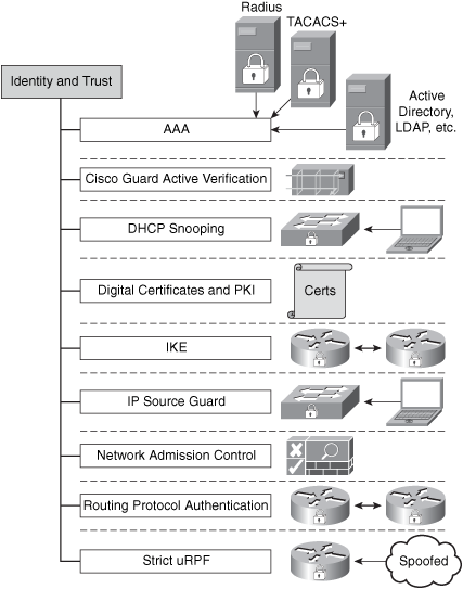
Identity and Trust
Identity and trust is one of the SAVE pillars. You should consider deploying a complete trust and identity management solution for secure network access and admission at every point in the network. The following are the most common technologies that are part of the identity and trust pillar:
• Authentication, authorization, and accounting (AAA)
• Cisco Guard active verification
• Digital certificates and PKI
• Internet Key Exchange (IKE) protocol
• Network Admission Control and 802.1x
• Routing protocol authentication
• Strict Unicast Reverse Path Fowarding (Unicast RPF)
These technologies are illustrated in Figure 7-7.
Figure 7-7. Identity and Trust
AAA
In Chapter 1, "Overview of Network Security Technologies," you learned the basic concepts of AAA. In Chapter 2, "Preparation Phase," you learned best practices for enabling authentication on networking devices for infrastructure protection. In this chapter, AAA concepts are aligned to the identity and trust pillar. A lack of appropriate user management techniques creates numerous direct business risks, including lower productivity, duplicate and conflicting user information, lack of information security, and difficulty in evaluating regulatory compliance. AAA goes beyond the normal authentication and authorization when accessing network devices for management purposes. You should implement a combination of authentication, access control, and user policies to secure network connectivity and resources to which only specific users should be provided access. This access includes the authentication of databases, web servers, e-mail, and other applications, in addition to authentication of users when they attempt to access network segments and their resources.
Other examples include authentication for remote access VPN and authentication of wireless users. The identity lifecycle consists of account setup, maintenance, and teardown. Account setup includes giving users the appropriate level of access to resources necessary to do their jobs. Account maintenance consists of keeping user identity information up-to-date and appropriately adjusting levels of access to resources needed to conduct business. Account teardown consists of deactivating the user account when the user is no longer affiliated with the company.
Stronger forms of authentication, such as PKI and one-time passwords (OTP), are increasingly used to control user access to corporate resources. Several solutions provide these kinds of services. You should always look for solutions that provide flexible authorization policies that are tied to the user identity, the network access type, and the security of the machine used to access the network. In addition, the ability to centrally track and monitor the connectivity of network users is of primary importance in isolating unwanted and excessive use of valuable network resources.
Note
Management, monitoring (correlation), and isolation are discussed later in this chapter, because they are separate SAVE categories or pillars.
As you learned in Chapter 1, TACACS+ and RADIUS are the most commonly used AAA protocols. Cisco Secure ACS supports both of these protocols and provides support for advanced authentication mechanisms, including the interoperability to external directory services, OTP servers, PKI, and other authentication solutions.
Cisco Secure ACS is an important component of the Cisco Identity-Based Networking Services (IBNS) architecture based on port-security standards such as 802.1x (an IEEE standard for port-based network access control). It is also the "brains" behind the Cisco Network Admission Control (NAC) Framework solution.
Note
Examples of the use of Cisco Secure ACS are discussed in the case studies included in Chapter 12, "Case Studies." The Cisco Secure ACS documentation is located at http://www.cisco.com/en/US/products/sw/secursw/ps2086/tsd_products_support_maintain_and_operate.html.
A good white paper on how to place the Cisco ACS servers within your network is located at http://www.cisco.com/en/US/products/sw/secursw/ps2086/products_white_paper09186a0080092567.shtml.
Cisco Guard Active Verification
The Cisco Guard provides multiple layers of defense to identify and block all types of attacks with extreme accuracy. It has integrated dynamic filtering capabilities and active verification technologies. These capabilities and technologies are implemented through the use of a patented Multiverification Process (MVP) architecture, which can process suspicious flows by applying numerous levels of analysis. The MVP enables malicious packets to be identified and removed, while allowing legitimate packets to flow freely.
Note
In Chapter 3, "Identifying and Classifying Security Threats," you learned how to use the Cisco Guard in conjunction with the Cisco Detector and other third-party solutions to identify and classify attacks.
DHCP Snooping
DHCP snooping is another technology or feature that can be considered part of identity and trust. It is a DHCP security feature that filters DHCP messages by building and maintaining a binding table. This table contains information that corresponds to the local untrusted interfaces of a switch, such as:
• MAC address of the device connected to the switch
• IP address of the device connected to the switch
• DHCP lease time
• DHCP binding type
• VLAN number
• Interface information
Note
The DHCP snooping table does not contain information regarding hosts interconnected with a trusted interface. An untrusted interface is an interface that is configured to receive packets from an untrusted network or device. A trusted interface is an interface that is configured to receive only messages from within the trusted network or device.
You can configure DHCP snooping for a single VLAN or a range of VLANs. The following example shows how to enable DHCP snooping on VLANs 10 through 50:
Example 7-1. IP DHCP Snooping
!enable DHCP snooping globally
!
ip dhcp snooping vlan 10 50
!apply DHCP snooping on VLANs 10 to 50
!
ip dhcp snooping information option
!
interface GigabitEthernet1/1
ip dhcp snooping limit rate 100
!this interface is classified as an untrusted interface,
and the rate limit is
configured.
!You may not want to configure untrusted rate limiting to more than 100 pps.
!Normally, the rate limit applies to untrusted interfaces.
!If you want to set up rate limiting for trusted interfaces, keep in mind that
trusted
!interfaces aggregate all DHCP traffic in the switch, and you will need to adjust
the rate
!limit to a higher value.
You can use the show ip dhcp snooping command to verify your configuration, as shown in the following example:
Example 7-2. Ouput of the show ip dhcp snooping command

In the previous example, you can see that DHCP snooping is enabled on VLANs 10, 20, 30, 40, and 50 (which are VLANs enabled on this switch). The interface GigabitEthernet1/1 is an untrusted interface, and rate limit is applied to 100 packets per second (pps). To configure an interface as a trusted interface, you must use the ip dhcp snooping trust interface subcommand.
IP Source Guard
IP Source Guard is a Layer 2 feature that works in conjunction with DHCP snooping. When IP Source Guard is enabled, all IP traffic on the port is initially blocked, with the exception of DHCP packets that are processed by the DHCP snooping feature (if enabled). After the end host receives a valid IP address from the DHCP server, or when a user configures a static IP source binding, a Port Access Control List (PACL) is applied on the port to restrict the client IP traffic to specific source IP addresses that are configured in the binding configuration. The switch drops all IP traffic with a source IP address other than that in the IP source binding.
An important note to remember is that if you configure IP Source Guard on a trunk port with a large number of VLANs that have DHCP snooping enabled, you might run out of ACL hardware resources, and depending on your platform, some packets might be switched in software. You can configure two levels of IP traffic filtering with IP Source Guard:
• Filtering source IP addresses: Only IP traffic with a source IP address that matches the IP source binding entry is permitted.
• Filtering on Source IP and MAC address: This is based on source IP address and its associated MAC address.
To enable IP Source Guard, use the ip verify source vlan dhcp-snooping interface subcommand, as shown in the following example:
interface GigabitEthernet1/1
ip verify source vlan dhcp-snooping
To verify the configuration, you can use the show ip verify source interface gigabitEthernet 1/1 command, as shown in the following example:

Digital Certificates and PKI
Digital certificates and PKI are also technologies that are used for trust and identity. Digital certificates bind an identity to a pair of electronic keys that can be used to encrypt and sign digital information. A digital certificate makes it possible to verify a claim that someone has the right to use a given key. This verification helps to prevent people from using phony keys to impersonate other users. Used in conjunction with encryption, digital certificates provide a more complete security solution than traditional username and password schemes. Digital certificates ensure the identity of all parties involved in a transaction.
The following are some of the most common uses of digital certificates:
• IPsec VPN tunnel authentication
• SSL transactions
• Code signing
• Application authentication (that is, e-mail, e-commerce, and so on)
IKE
IKE provides authentication mechanisms for IPsec VPN tunnels. This protocol is also an example of identity and trust technologies.
Note
Detailed information on IKE authentication mechanisms is covered in Chapter 1.
Network Admission Control (NAC)
NAC is also an example of a trust and identity technology. As you learned in Chapters 1 and 2, NAC appliance and framework provide a solution to evaluate whether end-host workstations are compliant with security policies before they enter the network. These policies can include antivirus, antispyware software, operating system updates, security patches, and other preconfigured options. In addition, the role-based authentication features provide more granular access to end hosts and users.
Routing Protocol Authentication
Another example of a trust and identity technique is the implementation of routing protocol authentication. Border Gateway Protocol (BGP), Enhanced Interior Gateway Routing Protocol (EIGRP), Open Shortest Path First (OSPF), Routing Information Protocol (RIP) and Intermediate System-to-Intermediate System Protocol (IS-IS) all support various forms of authentication mechanisms.
Note
These authentication mechanisms are discussed in Chapter 2 in detail.
Strict Unicast RPF
Strict Unicast RPF is an antispoofing mechanism that verifies the source address of a packet received on a router interface by verifying the forwarding table of the router. If the source address is reachable through the same interface on which the packet was received, the router processes the packet; if not, the packet is dropped. You can also categorize Unicast RPF as a trust and identity mechanism.
Note
Unicast RPF is discussed in Chapter 2.
Visibility
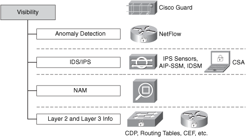
Network visibility is one of the most important pillars within the SAVE framework. In fact, two of the most important components of SAVE are visibility and control. The following are the most common technologies that can be used to obtain and maintain complete network visibility:
• Anomaly detection
• Intrusion detection system/intrusion prevention system (IDS/IPS) [IOS, Cisco Security Agent (CSA), network-based intrusion detection system/network-based intrusion prevention system (NIDS/NIPS)]
• Cisco Network Analysis Module (NAM)
• Layer 2 and Layer 3 information [Cisco Discovery Protocol (CDP), routing tables, Cisco Express Forwarding (CEF) tables]
These are illustrated in Figure 7-8.
Figure 7-8. Technologies That Help to Achieve and Maintain Complete Network Visibility
Anomaly Detection
Anomaly detection can be performed by various tools that provide insightful information on exactly what is happening within your network. These tools or technologies include the following:
• NetFlow
• Arbor Peakflow SP and Peakflow X
• Cisco Anomaly Detector XT
Note
Anomaly detection technologies and solutions are discussed in Chapters 1 and 2.
IDS/IPS
IDSs and IPSs also provide visibility into what is happening on the network. Most of the network IDS and IPS systems rely on signatures for detection and protection. For this reason, it is extremely important to keep signatures up-to-date and to tune the IDS/IPS devices accordingly. Cisco IPS 6.0 now supports anomaly detection capabilities that allow you to detect day-zero vulnerabilities more easily.
Note
An introduction to network IDS and IPS systems is covered in Chapter 1. Chapter 3 teaches you how to use network IDS and IPS systems to successfully identify and classify security threats. The configuration of IPS systems is covered within the case studies included in Chapter 12.
Host-based intrusion prevention systems, such as the Cisco Security agent, also provide information about the behavior of end-host systems by extending the visibility to each end point (host or servers).
Cisco Network Analysis Module (NAM)
The Cisco NAM is an integrated network monitoring solution for the Cisco Catalyst 6500 series switches. Ciso NAM is designed to give you visibility into the network by showing you information about applications running on your network and the performance of these applications. The Cisco NAM solution includes a web-based traffic analyzer GUI that presents statistical information to the administrator. The Cisco NAM uses Management Information Bases (MIB) for Remote Monitoring II (RMON II), Differentiated Services Monitoring (DSMON), Switch Monitoring (SMON), and other mechanisms to analyze and store the collected data.
Note
The following link provides detailed information about NAM: http://www.cisco.com/en/US/products/hw/modules/ps2706/ps5025/index.html.
The configuration guide is located at http://www.cisco.com/en/US/products/hw/switches/ps708/products_configuration_guide_book09186a00805e081e.html.
Layer 2 and Layer 3 Information (CDP, Routing Tables, CEF Tables)
Layer 2 and Layer 3 routing features can provide insightful information and increase visibility. Features such as CDP, CEF, and IP routing tables can give you topological information about the network. It is important to notice that in the hands of the enemy, tools like CDP can be destructive. Therefore, it is recommended that you enable CDP only on trusted interfaces.
Note
For more information on best practices to use when implementing CDP, refer to Chapter 2.
Correlation
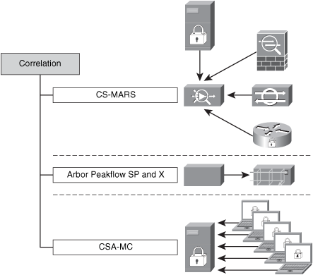
In previous chapters, you learned the different aspects of event correlation. For example, you learned that the more complex the network and devices deployed, the more event messages, alarms, and alerts these devices will generate. In the end, far more data is generated than anyone can easily scan, and it is located in numerous places. In this chapter, you learn the importance of event correlation for maintaining good visibility of what is happening in the network. This chapter also describes tools and technologies you can deploy to successfully correlate events, while maintaining visibility and control of the network. Event correlation tools enable you to efficiently use your staff time and skills, and they prevent revenue loss resulting from downtime. The following are examples of correlation tools:
• Cisco Security Monitoring, Analysis, and Response System (CS-MARS)
• Arbor Peakflow SP and Peakflow X
• Cisco Security Agent Management Center (CSA-MC) basic event correlation
These tools are illustrated in Figure 7-9.
Figure 7-9. Example of Tools That Help You Maintain Network Visibility
CS-MARS
CS-MARS supports events from routers, switches, firewalls, VPN devices, IPS/IDS solutions, operating system logs, application logs, and many other items. It supports both Cisco and non-Cisco devices.
Note
Chapter 3 teaches how you can use CS-MARS to successfully identify and classify security threats. The configuration of CS-MARS is covered within the case studies included in Chapter 12.
Arbor Peakflow SP and Peakflow X
Arbor Peakflow SP (for service providers) and Peakflow X (for enterprises) are excellent tools that allow you to obtain network visibility. Based on information collected from routers, such as interface statistics and NetFlow, Peakflow SP and Peakflow X can show you details of the traffic traversing throughout your network.
Note
For more information about these tools, go to http://www.arbor.net.
Arbor has excellent white papers about anomaly detection and combating day-zero threats at http://www.arbor.net/resources_researchers.php.
Cisco Security Agent Management Console (CSA-MC) Basic Event Correlation
CSA-MC can also provide you with basic host-based event correlation. You can gain visibility of what exactly is happening within each endpoint (user workstations and servers).
Instrumentation and Management
Instrumentation and management is also an important category within the SAVE framework. You should always implement protocols and mechanisms that achieve the management of every network device. Having good instrumentation and management mechanisms in place not only allows you to provision configurations to your network devices, but it also helps you to maintain control of your environment. Some examples of management and instrumentation tools are as follows:
• Cisco Security Manager (CSM)
• Configuration logger and configuration rollback
• Simple Network Management Protocol (SNMP) and remote monitoring (RMON)
• Syslog
These tools are illustrated in Figure 7-10.
Figure 7-10. Example of Instrumentation and Management Tools

Cisco Security Manager
CSM helps you configure Cisco firewalls, IPS devices, and VPN tunnels easily. It not only saves you time in the provisioning phase, but it can also be used to update enforcement policies in firewalls and routers when needed. CSM achieves scalability through policy-based management techniques that are used to simplify administration.
Configuration Logger and Configuration Rollback
The Cisco IOS configuration logger logs all changes that are manually entered at the command-line prompt. In addition, it can notify registered clients about any changes to the log.
Note
The contents of the configuration log are stored in the run-time memory; the contents of the log are not persisted after reboots. The Configuration Logger Persistency feature allows you to keep the configuration commands entered by users after reloads. You can enable the Configuration Logger Persistency feature by using the archive log config persistent save command.
The Cisco IOS Software configuration rollback feature allows you to keep a journal file containing a log of the changes and discard them if needed. The purpose of this feature is to revert (or roll back) to a previous configuration. You can use the configure replace command to roll back to a previous configuration state.
Note
More information about the Cisco IOS configuration rollback feature is located at http://www.cisco.com/en/US/products/sw/iosswrel/ps5207/products_feature_guide09186a0080356ea5.html#wp1066264.
Embedded Device Managers
In small environments, you can use embedded devices managers to configure and manage network access devices such as routers, switches, firewalls, IPS devices, and others. Numerous Cisco devices come with an embedded device manager. Examples include the following:
• Cisco Adaptive Security Device Manager (ASDM): Manages Cisco PIX and Cisco Adaptive Security Appliance (ASA) security appliances
• Cisco IPS Device Manager (IDM): Manages Cisco IPS sensors, in addition to Advanced Inspection and Prevention Security Services Module (AIP-SSM) for the Cisco ASA
• Security Device Manager (SDM): Manages Cisco IOS routers
Cisco IOS XR XML Interface
The Cisco IOS XR software supports an extensible markup language (XML) application programming interface (API) that helps you develop external management applications for routers that run Cisco IOS XR software.
Note
The following site has detailed information about the Cisco IOS XR XML interface:
http://www.cisco.com/en/US/products/ps5845/tsd_products_support_series_home.htmlSNMP and RMON
SNMP allows you to exchange management information between network devices and central management servers. SNMP is the most commonly used network device management protocol.
Note
In Chapter 2, you learn the basics of SNMP and what is most important: how to secure it.
The RMON protocol provides you with freedom when selecting network-monitoring probes and consoles with features that not only provide ease of management, but also can be used for greater visibility and control of the network.
Syslog
In Chapters 2 and 3, you learn how syslog can provide you with details on what is happening in network devices, while also allowing you to achieve more control and visibility of the network. Firewalls, routers, switches, and other networking devices can send insightful information to administrators via syslog. The combination of syslog and event correlation systems gives you powerful capabilities.
Isolation and Virtualization
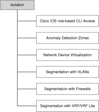
The fifth pillar in the SAVE framework addresses network isolation and virtualization. Several isolation and virtualization techniques and tools are available, including the following:
• Cisco IOS Role-Based CLI Access (CLI Views)
• Network device virtualization
• Segmentation with VRF/VRF-Lite
These techniques and tools are illustrated in Figure 7-11.
Figure 7-11. Examples of Isolation and Virtualization Techniques and Tools
Another isolation technique is maintaining separation between the different network planes. For example, keep the data plane separate from the control and management planes, by also implementing the necessary policies to protect each of them.
Cisco IOS Role-Based CLI Access (CLI Views)
You can consider the Cisco IOS routers Role-Based CLI Access feature a form of virtualization. This feature, otherwise known as CLI Views, allows you to define a virtual set of operational commands and configuration capabilities that provide selective or partial access to Cisco IOS exec and configuration mode commands. A view is a framework of policies that defines which commands are accepted and which configuration information is visible to the user based on his role.
Note
The following site has detailed information about this feature:
Anomaly Detection Zones
The Cisco Detector XT and the Cisco Guard XT allow you to configure zones to categorize and define anomaly detection policies for more granularity and customization. The following are examples of zones you can configure within the Cisco traffic anomaly detectors:
• Collections of servers or clients
• Collections of routers or other network access devices
• Network links, subnets, or entire networks
• Single users or whole companies
• Internet service providers
Note
The following site provides step-by-step instructions on how to create zones in Cisco Detector and Guard implementations:
Network Device Virtualization
Several networking devices support virtualization. You can take advantage of device virtualization to segment and apply different policies within your infrastructure, while saving money in hardware. For example, you can partition a single hardware device into multiple virtual devices. In most cases, each virtual device acts as an independent device. The following devices support virtualization:
• Cisco PIX
• Cisco ASA
• Cisco Firewall Services Module (FWSM) for the Catalyst 6500 series switches
• Cisco IPS sensors running version 6.x or later
• The Cisco Application Control Engine (ACE) family for the Cisco Catalyst 6500 series switches
The Cisco PIX, Cisco ASA, and FWSM can be configured in multiple context mode in which each context has its own security policy, interfaces, and administrators. Having multiple contexts is similar to having multiple standalone devices. Figure 7-12 illustrates how a Cisco FWSM is deployed with three contexts (admin, context-1, and context-2) to segment different servers in a data center).
Figure 7-12. Security Contexts in FWSM

Many features are supported in Cisco ASA, Cisco PIX, and Cisco FWSM running in multiple-context mode; however, some features are not supported, including VPN and dynamic routing protocols.
Note
Chapter 10, "Data Center Security," includes sample configurations of Cisco FWSM virtualization to provide data center security. Chapter 12, "Case Studies," also has configuration examples of virtualization in Cisco PIX and Cisco ASA security appliances.
Segmentation with VLANs
You can achieve network segmentation and isolation in many ways. The use of VLANs is one of the most commonly used methods because of its simplicity and ease of deployment. Figure 7-13 illustrates how you can isolate/segment different types of devices just by using VLANs.
Figure 7-13. Segmentation Using VLANs
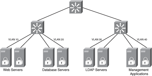
In Figure 7-13, a set of web, database, Lightweight Directory Access Protocol (LDAP), and management servers are isolated by simply configuring four separate VLANs (VLANs 10, 20, 30, and 40, respectively).
Segmentation with Firewalls
In many situations, you can simply segment or isolate parts of the network, servers, or users by placing firewalls. Firewalls also provide more granular policy enforcement mechanisms. Sometimes you can use firewalls with VLAN segmentation, as illustrated in Figure 7-14.
Figure 7-14. Segmentation Using VLANs and Firewalls for Policy Enforcement
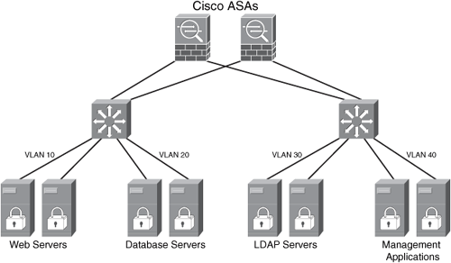
In Figure 7-14, the same servers and the four separate VLANs are configured. In addition, a pair of Cisco ASAs are placed to provide segmentation services while enforcing more granular security policies.
Segmentation with VRF/VRF-Lite
You can also use Multiprotocol Label Switching (MPLS) VPN routing and forwarding (VRF) or the MPLS VRF-Lite feature on Cisco IOS routers for network segmentation purposes. This concept is illustrated in Figure 7-15.
Figure 7-15. Segmentation Using VRF and VRF-Lite

The main challenge of implementing VRFs and VRF-Lite is that most enterprises do not run MPLS within their corporate network. More importantly, their staffs do not have the skills to implement MPLS because it is a complicated routing technology. This segmentation technique is mainly implemented by service providers.
Policy Enforcement
The last pillar in the SAVE framework defines policy enforcement. You can enforce policy in many ways. Figure 7-16 illustrates some examples of techniques and features that allow you to enforce security policies within your organization:
The following examples are illustrated in Figure 7-16.
• Cisco Guard XT MVP: With the Cisco Guard XT, you can do per-flow-level attack analysis, identification, and mitigation. This is an example of policy enforcement, because the Cisco Guard XT MVP architecture provides multiple layers of defense that can block attack traffic, while allowing legitimate transactions to pass.
• Control Plane Policing: In Chapter 2, you learn best practices when deploying Control Plane Policing (CoPP) in your network. CoPP is also used to enforce predefined policies to protect the control plane of Cisco IOS routers in your network.
• Encryption policies: You can enforce security encryption policies that best fit your environment in IPsec site-to-site and remote access VPN tunnels.
• Firewalls, packet filters, and ACLs: Firewalls, packet filters, and ACLs (including VLAN ACLs [VACLs] and policy-based ACLs in the Catalyst 6500) are the methods most commonly used to enforce security policies for segmentation and protection of network resources.
• NAC policy enforcement: You can configure NAC Appliance and NAC Framework policies to ensure that only compliant machines can enter the network. Based on your configured policies, you can quarantine and remediate noncompliant machines.
• Policy-based routing (PBR): You can also use PBR on routers and Layer 3 devices to define enforcement policies for traffic within your network.
• Remotely triggered black holes (RTBH): In previous chapters, you learn how you can block attack traffic or infected hosts using RTBH. RTBH is another example of how you can reactively enforce policies within your network.
Figure 7-16. Policy Enforcement

Visualization Techniques
This section includes a few examples of how you can create topology maps and other diagrams to visualize your network resources and apply SAVE. These diagrams give you the basic idea so that you can then customize the diagrams to fit your organizational needs.
You can create circular diagrams like the one illustrated in Figure 7-17. Typically, these types of diagrams include resources that surround a critical system or area of the network you want to protect. In Figure 7-17, a cluster of database servers is illustrated in the center of the diagram. Several layers describe the devices in the topology in relation to different sections of the network.
Figure 7-17. Topology Map Visualization
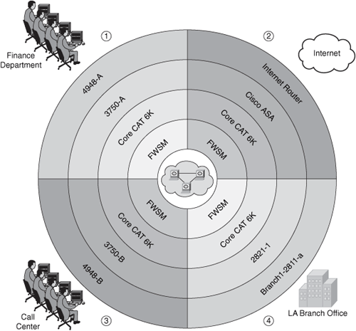
The illustration in Figure 7-17 helps you visualize and understand the different layers of protection you can apply within your network to protect the mission-critical systems. The diagram in Figure 7-17 has four major sections that portray the path from and to the protected system and the following sections of the network:
1. Finance department users
2. Internet
3. Call Center
4. Branch Office in Los Angeles, California (LA)
You can also visualize packet flows and understand how security policies can be applied to each network device to protect critical systems and the infrastructure as a whole. An example is illustrated in Figure 7-18.
Figure 7-18. Traffic Flow Visualization

Figure 7-18 illustrates an example of the packet flow when a user from the finance department accesses the Internet. There you can see the devices that these packets touch and the relation to the critical systems.
You can identify where you can apply the technologies that belong to each SAVE pillar. For example, Figure 7-19 shows how you can apply technologies that enable you to gain and maintain visibility of what is happening in your network.
Figure 7-19. Visibility Techniques Applied
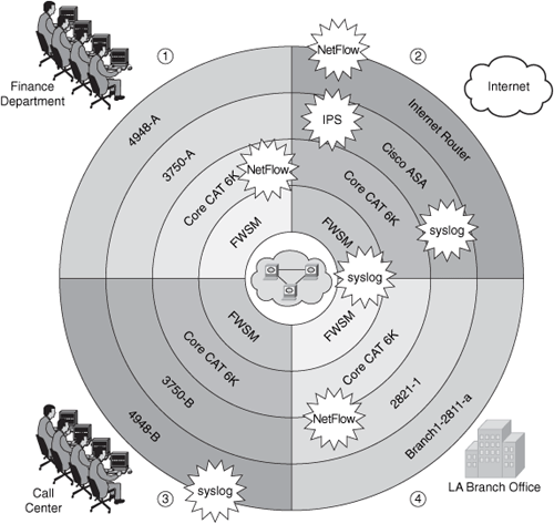
Figure 7-19 shows you how you can enable syslog on devices such as the switches, routers, FWSM for the Cisco Catalyst 6500 series switches, and Cisco ASA. It also shows you places where you want to enable NetFlow, IPS services, and other features.
Figure 7-20 shows where you can enforce policies to restrict access.
Figure 7-20. Policy Enforcement Visualization

You can apply ACLs and IP inspection features on the Cisco ASA and the FWSM. In addition, you can apply VACLs on the access switches and antispoofing and infrastructure ACLs on the Internet router and other routers within the network. You can also enforce strict IPsec policies for the site-to-site connectivity between the main office and the branch office.
Note
Antispoofing and infrastructure ACLs are discussed in Chapter 2, "Preparation Phase." Chapter 12, "Case Studies," also provides some examples within the case studies it covers.
You can also create similar diagrams to visualize where you can apply the technologies and features described on each of the pillars in SAVE. SAVE advocates the understanding of device roles and their appropriate configuration. For example, the Internet edge routers do not have the same role as the other routers within the topology in the previous examples. Despite that, Internet edge routers can be the same model and run the same software versions as other routers, and their configuration should be modeled after their role.
Note
The types of diagrams shown in Figures 7-18, 7-19, and 7-20 are not limited to only these technologies, features, and applications. You can customize them to your specific needs.
Summary
SAVE is a framework that was initially developed for service providers, but you can apply its practices to any organization. This chapter covers SAVE in detail. Examples of technologies within the six SAVE main categories are discussed. Visibility and control are two of the most important topics and concepts within SAVE. This chapter provides examples of techniques and practices that can allow you to gain and maintain visibility and control over the network during normal operations or during the course of a security incident or an anomaly in the network.
