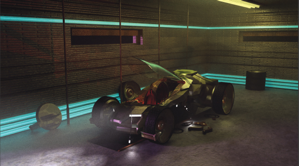
With this case study, we’ll light an interior scene featuring a futuristic vehicle in a garage-like setting (Figure C2.1). Exercise steps are outlined for Autodesk Maya but can also serve as a general guideline for other 3D programs.
Figure C2.1 The interior scene with renderCamera highlighted.
Original 3D vehicle and garage model created by 3DHaupt, licensed via Creative Commons Attribution 3.0 Unported (CCBY3.0).
We’ll begin the exercise by answering important lighting questions introduced in Chapter 3:
What is the context of the lighting? We are lighting a single shot, so it does not need to match any particular source.
What is the location of the lighting? Interior.
What is the time of day? We’ll assume it is nighttime. Night scenes are often more difficult to light due to the dependence on multiple man-made light sources.
What is the time period? This is a science-fiction piece, so the time period is sometime in the near future.
What are the properties of the light sources? We’ll use a combination of naturalistic and stylistic lighting with an arbitrary number of artificial light sources. Although we have no specific lighting reference, we’ll try to make the lighting look plausible for the location. As such, we will light with the following light sources:
A) Overhead light as a key. There is geometry in the scene that represents this rectangular bank of lights.
B) Outdoor light as fill. We will assume that there is an outdoor light, such as a floodlight, that reaches the interior through the windows and doors.
C) Incandescent wall trim as a utility light. There are narrow bands built into the wall that serve as futuristic light source. We can treat these bands as if they were neon tubes or arrays of LED lights. We’ll make these lights heavily saturated to create a stylistic look.
D) Vehicle lights as utility lights. A futuristic vehicle serves as the center of the scene. We’ll mimic dash lights, headlights, and small works lights.
In addition, we’ll add pool lights to illuminate parts of the scene missed by the other lights.
1.Launch Autodesk Maya. Open the Garage-Start.ma file from the Project-FilesMaya directory. Take a few minutes to familiarize yourself with the scene contents. The scene contains a partial garage model, a vehicle, and a few props. A camera named renderCamera serves as the rendering camera. A second camera, named persp, is left as a work camera and is not intended for rendering. If you are not using Maya, a Garage-Start.fbx file is saved to the same directory.
2.In general, I suggest starting the lighting setup by placing the strongest key light or key lights. However, with this scene, we’ll start with a fill light that simulates an exterior light source that filters through the two small windows and the open side of the garage. Create a directional light (Create > Lights > Directional Light). Feel free to scale up the light icon (it does not affect the light quality). Move the light away from the model so it is easier to see. Select the renderCamera viewport (click on the viewport panel bar to select it). Choose Lighting > Use All Lights and Lighting > Shadows from the viewport menu. By default with recent versions of Maya, ray trace shadows are activated for the light and are visible in the viewport. Rotate the light until the light creates a pattern on the floor by entering through one or more of the windows. You can allow the light to enter through the open side of the garage. We can treat the light as if it is also entering through a large, open garage door. For example, a rotation of approximately -149, 50, 12 creates the light pattern seen in Figure C2.2.
3.Create an area light (Create > Lights > Area Light). Position the area light until it is directly under the modeled light fixture located on the ceiling above the vehicle. This light will serve as the strongest light and the key. Scale the light so it is roughly the same size as the fixture. Rotate the light so that it points downwards (Figure C2.3). (The light “tail” should point towards the floor.) Open the light’s Attribute Editor tab. Set the light color to yellow. Set the Decay Rate menu to Quadratic. Set the light’s Intensity value to1,000. (The large Intensity value is required because the light has a relatively small size within a relatively large set.) Open the directional light’s Attribute Editor tab. Set the directional light Intensity to 0.75 and Color to light purple. Although both lights receive ray trace shadow automatically, the directional light produces hard-edged shadows. Expand the Raytrace Shadow Attributes section for the directional light and set the Light Angle to 5; this makes the light rays divergent and softens the shadow edge.
Figure C2.2 A directional light is rotated to serve as an exterior light reaching the interior of the garage. The black area of the floor represents a ray trace shadow.Figure C2.3 An area light is translated, rotated, and scaled under the modeled light fixture. The light points downwards.
4.Now that there is a second light, feel free to adjust the rotation of the directional light. For example, rotate the light slightly so that it reaches the front of the vehicle. At any stage, you can return to a light and adjust its transformations and attribute values to improve the overall lighting quality. Change the directional light’s name to window_fill. Change the area light’s name to key. You can change an object name by double-clicking the name in the Outliner (Windows > Outliner) and typing a new name.
5.Open the Render Settings window (Windows > Rendering Editors > Render Settings). Set the Render Using menu to Maya Software. Although the Maya Software renderer is not a PBR renderer and offers few options, it produces sufficient quality to begin the lighting process. (If you are using different 3D software, you can select an equivalent default renderer.) Switch to the Maya Software tab, expand the Raytracing Quality section, and select the Raytracing checkbox. Ray tracing is necessary to render the ray trace shadows. Create a test render of renderCamera through the Render View window (Windows > Rendering Editors > Render View). Note that the render quality is poor by default. You can raise the render quality by changing the Edge Anti-Aliasing menu to High Quality through the Maya Software tab of the Render Settings window. The ray trace shadow quality will remain poor and appear grainy; we will improve the shadow quality in a later step. The initial render is illustrated by Figure C2.4. I suggest turning off the View Transform button provided by the Render View as it shows a gamma-adjusted version that appears too bright. See Case Study 1 for more information on this option.
Figure C2.4 The area light, placed under the modeled light fixture, serves as the key light. However, due to light decay, it does not reach all parts of the scene at equal intensity. The directional light is given a weaker intensity, a softer shadow, and is rotated to reach the front of the vehicle. The cyan of the wall trim and the white of the headlights and small work lights comes courtesy of material incandescence; the incandescence does not light nearby surfaces.
6.The cyan trim seen along the walls appears incandescent, thanks to the assigned material, but does not light the scene. We can use additional area lights to add cyan light to nearby surfaces. Create a new area light and scale, rotate, and translate it to match the first bank of trim along the bottom of the left wall. Point the light outward towards the vehicle. The light can intersect the floor of other nearby geometry such as the round hatch and spare wheel. Open the new light’s Attribute Editor tab and set the light color to cyan. Set the Decay Type to Linear and the Intensity to 3. A linear decay requires a far lower Intensity value than quadratic decay. That said, we want the cyan light to only reach a short distance into the room. Test render (Figure C2.5). Change the new light’s name to trim_fill.
Figure C2.5 A second area light is added to emulate cyan light generated by the incandescent trim. Note that the light does not reach the wall itself; this can be addressed in a later step.
7.Duplicate the newest area light three times (Edit > Duplicate with the light selected). Scale, rotate, and translate the three copies so that they provide cyan light for the other three sections of trim (Figure C2.6). Because there is little geometry near the top pieces of trim, you can point the corresponding lights towards the walls.
Figure C2.6 Wireframe showing the locations of the four area lights providing illumination for the incandescent trim. The two top lights point outwards and the two bottom lights point inwards.
8.Following a similar process, we can create light for the small white work lights that appear near the vehicle. However, instead of using area light, point lights are more appropriate for light bulbs. Create a new point light (Create > Lights > Point Light). Translate the new light so it sits directly beside the work light that hangs down near the vehicle’s front, frame-right bumper. Change the light’s name to work_fill. Open the light’s Attribute Editor tab. Set the light’s Decay Rate menu to Quadratic. Set the light’s Intensity to 5. We want the light to only illuminate a small area near the front of the vehicle. Duplicate the point light. Move the copy beside the cluster of three work lights that hang down on the visible side of the vehicle. We can use this light to emulate the illumination of all three lights as they are in close approximation. Set the new light’s Intensity to 10. Test render (Figure C2.7).
9.We can assume that the futuristic vehicle includes lighting in the cockpit. We can use this lighting to better define the seats and transparent, reflective canopy. Create a new point light. Change the new light’s name to cockpit_fill. Change its color to red. Translate the light so that it sits in front of one of the two screens built into the dash (Figure C2.8). Don’t let the light intersect any geometry (this will create unwanted shadows). Point lights, like directional and area lights, are given ray trace shadows by default with recent versions of Maya. Set the light’s Decay Rate to Linear and Intensity to 4. Test render. The red light fails to reach the back seat as it is shadowed by the front seat. Duplicate the light two times. Translate one copy to the opposite side of the dash. Translate the second copy behind the front seat so it illuminates the back seat. Set the Decay Rate of the third light to Quadratic so that it is weaker. Test render (Figure C2.9). Note that the red light reaches the side wall and appears as a red refraction and weak reflection on the canopy.
Figure C2.7 Render after the addition of area lights for the incandescent wall trim and point lights for the small work lights.Figure C2.8 Positions of three cockpit point lights indicated by the red arrows.Figure C2.9 Render after the addition of the red cockpit lights. The red light reaches the wall, making the otherwise plain wall more interesting.
“A day without sunshine is like, you know, night.”—Steve Martin
10.At this stage of the project, almost every portion of the scene receives some degree of light. However, the wheels remain very dark. The wheels facing the camera have almost no detail. We can remedy this by adding stylistic pools of light. Create a new point light. Change the light’s name to pool. Move the point light so that it sits near the rim of the back screen-right wheel (Figure C2.10). Change the light color to yellow, the Light Decay to Quadratic, and the Intensity to 400. We will pretend that the yellow light is related to the overhead light, although no specific light fixture for this light is visible. Test render. Duplicate the light. Move the copied point light so that it sits near the screen-right corner of the front bumper (Figure C2.10). Change the light color to white and the Intensity to 750. We will pretend that the white light arrives from a nearby work light although it is not physically accurate. Test render (Figure C2.11).
Figure C2.10 Positions of point lights placed near wheels indicated by red arrows.Figure C2.11 Render after addition of point lights near the wheels.
11.At this stage, it pays to examine the overall quality of the lighting. All the major light sources have been established with numerous lights. However, the saturated nature of the lights makes the result somewhat jarring. To avoid this, you can fine tune the light intensities and colors. For example, in Figure C2.12, the adjustments listed in Table C2.1 are made.
Light name
Intensity value
Color
Color value (RGB with 0 to 1.0 scale)
key
700
Desaturated yellow
1.0, 1.0, 0.5
cockpit_fill,
cockpit_fill1, and
cockpit_fill2
3
Red
1.0, 0.125, 0.125
trim_fill, trim_fill1,
trim_fill2, and
trim_fill3
2
Cyan
0, 0.7, 1.0
window_fill
0.5
Desaturated violet
0.9, 0.5, 1.0
work_fill
3
White
1.0, 1.0, 1.0
work_fill1
5
White
1.0, 1.0, 1.0
pool
3
Desaturated yellow
1.0, 1.0, 0.5
pool1
1
White
1.0, 1.0, 1.0
“The hard part is how to plan a picture so as to give to others what has happened to you. To render in paint an experience, to suggest the sense of light and color, of air and space”—Maxfield Parrish
Figure C2.12 Render after the adjustment of all the Intensity and Color values of all the lights in the scene.
12.The shadows currently visible in the scene are a product of the included geometry. That said, you are not limited by included geometry and can create additional shadows by creating 3D light flags. A light flag is a device used in photography and cinematography to block light; this often comes in the form of a fabric-covered frame. You can use any geometry in Maya to cast shadows; as long as the geometry is not visible in the render, it can serve as a flag. For example, create a primitive polygon helix (Create > Polygon Primitives > Helix). Translate, rotate, and scale the helix so it sits below the key area light (e C2.13 render. The helix serves as a flag, creating a new shadow on nearby surfaces. However, the helix is visible in the render. To avoid this, select the helix, go to the helix shape tab in the Attribute Editor, expand the Render Stats section, and deselect the Primary Visibility checkbox. Test render. Although the helix disappears from the render, it continues to cast shadows (Figure C2.14Continue to adjust the translation, rotation, and scale of the helix until it forms an interesting shadow. Ideally, the new shadow breaks up the otherwise plain floor on the right side of frame and reduces the intensity of the yellow light on the back of the vehicle. Note that the shadow cast by the helix is soft-edged if the helix is close to the area light and more hard-edged if placed further from the light (and closer to the surfaces receiving the shadow). Optionally, you can add additional polygon objects to create more complex shadows.
Figure C2.13 A primitive polygon helix is translated, rotated, and scaled so that it sits below the key area light at an angle. The helix serves as a light flag, creating a new shadow.Figure C2.14 Resulting render with a new shadow running from the right side of the left wall, down across the back right edge of the vehicle, and ending across the frame-right floor. The shadow location is indicated by the red line. The helix is not visible because its Primary Visibility checkbox is deselected. The new shadow adds visual interest by breaking up areas that possessed consistent brightness or color.
13.Thus far, we have rendered with low-quality shadows that create grainy shadow edges. You can improve the shadows by raising each light’s Shadow Rays value. The higher the Shadow Rays value, the smoother the shadow edge but the longer the render time. Thus, it’s best to incrementally raise the values and test render with each step until the render quality is satisfactory. For example, the values listed in Table C2.2 are used for the lights to create the render seen in Figure C2.15.
Light name
Shadow Rays value
key
32
cockpit_fill, cockpit_fill1, and cockpit_fill2
16
trim_fill, trim_fill1, trim_fill2, and trim_fill3
8
window_fill
16
work_fill and work_fill1
16
When working with point lights, you have the option of changing the light’s virtual width through the Light Radius attribute. Shadow Rays and Light Radius are located in the Ray Trace Shadows section of the light’s Attribute Editor tab. The larger the Light Radius value, the wider the light and the softer the shadow it creates. For example, you can set the Light Radius of the work_fill and work_fill1 lights to 3. Note that larger Light Radius values may require higher Shadow Rays values to create suitably high-quality shadows. At the same time, you can determine if any lights do not require cast shadows. For example, you can deactivate shadows for the pool and pool1 lights with little change to the resulting render seen in Figure C2.15. A matching scene file is included as Garage-Maya-Final.ma in the Project-Files Maya directory.
Figure C2.15 Render after the adjustment of the shadow attributes. Most of the grain associated with low-quality shadows is removed.
We can further improve the vehicle scene by switching to the Chaos Group V-Ray renderer and employing PBR to capture bounced light. In addition, we can emulate airborne dust and smoke by using volumetric fog. You can download a trial copy of V-Ray at www.chaosgroup.com.
1.Open the Render Settings window. Switch the Render Using menu to V-Ray. Test render. V-Ray launches its own variation of the Render view window, named V-Ray Frame Buffer. The renderer progressively refines the entire frame until the render is complete or the render is interrupted by the user. In addition, any changes to lights, materials, or geometry during the render causes the render to update the affected parts of the frame. You can press the Esc key or click the Stop Rendering button at the window’s upper-right corner to interrupt a render. To restart the render, press the Start Interactive Rendering at the upper-right corner of the window. See Case Study 1 for more information on this window.
2.Disable the Display Colors In sRgb Space button at the bottom-left of the V-Ray Frame Buffer window. This prevents an additional gamma correction from being applied to the render (the button is designed to preview linear color space renders, which does not apply to our project). With the button disabled, the render is nevertheless too bright (Figure C2.16). Because the scene uses standard Maya materials, which are not designed for PBR, the lighting does not translate directly to V-Ray. In addition, the various area lights are rendered as solid objects by V-Ray. The area lights that face away from the camera are rendered as black planes.
Figure C2.16 Initial V-Ray render. Area lights are rendered as solid planes.
3.Open the trim_fill light in the Attribute Editor. In the Object Display section, deselect Visibility. This hides the light from V-Ray render and the viewports. Repeat this process with trim_fill1, trim_fill2, and trim_fill3. We will gain back the blue fill through V-Ray rendering at a later step. Deselect Visibility for the key light. We’ll replace the key light with a new V-Ray Rect light. V-Ray, like many advanced renderers, provides its own lights. These offer the advantage of maximum compatibility with the renderer and often include specialized options. Choose Create > Lights > V-Ray Rect Light. Translate, rotate, and scale the new light so that it is roughly in the same position as the Maya key light. The light appears similar to Maya area lights but has a more distinct arrow indicating the direction of light flow. Name the new light VRayKey. Open the light’s Attribute Editor tab. Set the light color to pale yellow (1.0, 1.0, 0.5 in RGB). Set the Intensity Multiplier to 15. Note that the light is tailored for PBR by allowing you to set the intensity through such scale units as lumens or watts through the Units menu. Expand the Options section and select the Invisible checkbox. Test render. The lighting is similar to the Maya Software render (Figure C2.17).
4.The blue trim along the bottom of the walls create blue fill on the ground as a specular reflection. Hence, the original area lights in those regions are not needed. At this point, several surfaces appear too reflective, producing intense specular reflections. For example, the tires and seats possess increased specularity. Ideally, you can replace all the materials with V -Ray variations. This would allow you to add PBR accuracy to the material interpretation. V-Ray, like many advanced renderers, includes a library of compatible shaders accessible through the Hypershade window’s Create menu. As a shortcut, we can simply adjust a few of the Maya materials currently in the scene. Open the Hypershade window. Double-click the tire_mat material, which is a Phong. In the Attribute Editor, go to the Specular Shading section. Reduce the Cosine Power and Specular Color to low values. This darkens the specular reflection and makes the surface appear more matte-like. Test render. You can render regions in the V-Ray Render Buffer window by clicking the Region Render button at the top of the window so it turns blue, LMB-dragging a region box in the render area, and clicking the Start Interactive Rendering button at the top-right. To return to full-frame rendering, click the Region Render button so it is no longer blue. Repeat this process with the seat_mat material. As an additional adjustment, raise the Intensity value of the window_fill light to 1.0 to bring back some of the violet color on the ground that was lost when switching to V-Ray. Test render (Figure C2.18).
Figure C2.17 The trim area lights are hidden and the key area light is replaced by a V-Ray Rect light, returning the render to a state similar to the one produced by Maya Software.Figure C2.18 The materials assigned to the tires and seats are adjusted to reduce the specular reflectivity.
5.Many renderers offer the means to replicate participating media in the form of environmental fog. Environmental fog is generally created by a volumetric shader that emulates the media within a 3D volume. V-Ray provides a set of volumetric shaders for this purpose. To use such a shader, you must create a fog container. To do so, create a primitive cube (Create > Polygon Primitives > Cube). Scale and translate the cube so it surrounds the garage model. For the fog to be visible in the render, the rendering camera must sit outside the cube (Figure C2.19).
Figure C2.19 A primitive polygon cube is scaled to surround the garage and will serve as an environmental fog container. The rendering camera, seen as a green icon, is left outside the cube.
6.Assign the polygon cube to a new Lambert material (click the Lambert icon in the Create > Maya > Surface menu of the Hypershade window, select the cube, RMB-click over the new Lambert material in the Materials tab of the Hypershade, and choose Assign Material To Selection from the menu). Double-click the new material to open it in the Attribute Editor. Change Transparency to white so the polygon box is not seen during the render.
7.In Maya, volumetric shaders must be connected to a material’s shading group node. Shading groups are created automatically when a surface is assigned to a material. To find the correct shading group, RMB-click over the material icon in the Materials tab of the Hyperspace window and choose Graph Network from the menu. The shading network is displayed in the work area. A SG (Shading Group) node is connected to the material. Double-click the SG node to open it in the Attribute Editor. Click the checkered map button beside the Volume Material attribute. The Create Render Node window opens. Navigate to the Create > VRay > Volumetric section and click the VRay Environment Fog icon. A VRayEnvironmentFog1 shader is added to the scene. Test render. Fog appears but is so opaque that the garage is not visible.
8.To adjust the fog density, double-click the VRayEnvironmentFog1 icon in the Materials tab. In the Attribute Editor, set Fog Distance to 250. Fog Distance sets the fog density. Small values create a more opaque fog while larger values create a more transparent fog. For this scene, we want to make the fog relatively subtle. Change the Color to white and Emission to dark gray. Although the fog color is influenced by the color of lights in the scene, you can brighten the fog by raising these attribute values. The Emission attributes makes the fog self-illuminated. You can further adjust the self-illumination by adjusting the Emission Multiplier. Test render. The fog becomes more subtle (Figure C2.20). Note that the primitive helix used as a light flag casts a shadow into the fog. Hence, it may be necessary to adjust the helix translation and rotation. For example, move the helix farther away from the VRayKey light.
9.Thus far, we have not employed GI to calculate light bounce in the form of indirect illumination. You can activate indirect illumination when using V-Ray by going to the Render Settings window, switching to the GI tab, and selecting the On checkbox. You can make the environmental fog a part of the GI calculation by going to the VRayEnvironmentFog1 shader’s GI section and selecting the Scatter GI checkbox. Test render. The use of GI brightens the cyan wall trim as the incandescence is considered a light source. The cyan light also appears brighter along the floor. GI also affects the upper portions of the wheels, where bounce light from the floor reaches the tops of the rims. At this stage, a large amount of noise is apparent in the render; we’ll adjust the render quality settings at the last step to remove this.
Figure C2.20 Environmental fog is added to the scene. The fog appears the most dense at the back corner of the room and most intense under the ceiling key light. The overall contrast of the render is reduced by the presence of fog. The rotation of the helix light flag is adjusted; its shadow appears within the fog below the key light.Figure C2.21 GI is activated, creating light bounce. As a result, the cyan wall trim appears to glow.
10.V-Ray environmental fog reacts to lights placed within its volume. Hence, you can form beams of light. For example, we can create headlight beams for the vehicle. To do so, create a new spot light (Create > Lights > Spot Light). Rename the new light headlight. Translate, rotate, and scale the new light so that it protrudes from one of the vehicle’s headlight squares (Figure C2.22). Open the light’s Attribute Editor tab. Turn off shadows by deselecting Use Ray Trace Shadows. If the light is not casting shadows, you are free to let the light intersect the vehicle and floor geometry. Set the light’s Cone Angle to 5 and Penumbra Angle to 15. Set the Decay Rate to Linear and Intensity to 350. Test render. A light beam appears in the fog. Feel free to adjust the light Intensity to make the beam brighter or darker. When you are satisfied with the adjustments, duplicate the light and position the copy in front of the remaining headlight. Test render (Figure C2.23)
Figure C2.22 Two Maya spot lights are placed in front of the vehicle to form headlight beams. The lights illuminate the environment fog so long as they are within the fog container.Figure C2.23 The resulting headlight beams. The floor is illuminated where the spotlights intersect the floor geometry. A large Penumbra Angle value on each light ensures a soft edge to the light throw.
11.As a final step, we can improve the render quality and remove noise that is present in a number of areas. (The noise is the heaviest along the top of the vehicle, within the white headlight beams, and directly below the yellow ceiling light.) This requires the adjustment of V-Ray sampling. Open the Render Settings window. Switch to the VRay tab. By default, V-Ray uses the progressive style of sampling, where the entire render is progressively sampled and the render image is gradually refined. This approach is suitable for testing. You can improve the result of this style of rendering by increasing the Min Subdivs and Max Subdivs attribute values. These values set the degree of subpixel sampling. For example, you can set Min Subdiv to 16 and Max Subdiv to 128. Higher values will slow the render significantly but will improve the resulting quality. Another approach requires the use of adaptive sampling where additional subpixel sampling occurs where there is the highest contrast between neighboring pixels. To switch to this approach, change the Sampler Type menu to Bucket. With this setting, it’s not necessary to increase the Min Subdivs and Max Subdivs values unless the render contains thin lines or heavy motion blur. Sampler Type, Min Subdvis, and Max Subdivs attributes are located in the Image Sampler section near the top of the VRay tab.
A final render is illustrated by Figure C2.24. The final Maya Software scene is included in the Proj-ect-FilesMaya directory as Garage-Maya-Final.ma. The final V-Ray scene is included in the Project-FilesMaya directory as Garage-Vray-Final.ma.
Figure C2.24 The final render.
“It’s like driving a car at night. You never see further than your headlights, but you can make the whole trip that way”—E. L. Doctorow