

Each light source, whether it’s natural or artificial, has unique properties. You can emulate each light source type by carefully choosing a 3D light or lights and selecting appropriate translations, rotations, intensities, colors, shadow types, and shadow qualities. This is equally true when lighting locations or lighting characters.
This chapter includes the following critical information:
“Light Painting, domes, on the banks of the Swan River Perth Western Australia.” by Gnangarra licensed via Creative Commons Attribution 2.5 Australia (CC BY 2.5 AU).
Emulating Natural Light Sources
In previous chapters, we discussed the basic approach to lighting a 3D scene. We’ve also reviewed common 3D lights types, light properties, shadow variations, and shader categories. In this chapter, we’ll put that knowledge to use by replicating specific light sources within 3D scenes. We’ll begin by recreating natural light sources, including the sun at different times of day and candle flames.
SIDEBAR
Source Models and Textures
The 3D models and textures used in this chapter are included with the book’s exercise material, which you can find at:
www.routledge.com/9781138737570
The models are saved in a binary FBX format (2014/2015 version), which can be imported into a wide range of 3D programs. The textures are saved as PNG and JPEG bitmaps. The models and textures are licensed via Creative Commons. Licensing information for the models is included with the captions of the figures in this chapter. In addition, model-license.xls and texture-license.xls are included with the exercise files. See the Introduction for more information.
If you choose to import an FBX file, you may need to relink, reload, or map the texture bitmaps through their corresponding shaders. If you are working with a 3D program that is unable to read the shader set-ups properly, you can still apply the lighting techniques with simple shaders that only provide a solid color. Alternatively, you can assign your own unique textures.
Mid-day Sun
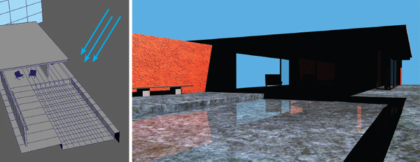
Our first task is to light the model of a modern house, as seen in Figure 4.1. The green camera icon indicates the rendering camera placement. This model is saved as house.fbx with the exercise files. The rendering camera is named renderCamera.

Original 3D house model created by claudio andres. licensed via Creative Commons Attribution 3.0 Unported (CC BY 3.0).
We’ll begin this exercise by answering the lighting questions introduced in Chapter 3
What is the context of the lighting? This is a lighting exercise, so we are not concerned with matching any other project.
What is the location of the lighting? Exterior.
Does the location exist? The model is based on a real location but we are not concerned with matching it in a photorealistic way. However, we do want the lighting to look natural.
What is the time of day? Mid-day.
What is the time period? The present.
What are the properties of the light sources? This will be 2-point lighting:
A) Sun light as the key light. This will be hard lighting with clearly defined shadow edges.
B) Net reflected sun light serving as fill. The light bounces off the concrete, marble, and stucco surfaces, working its way inside the unlit interior.
Before we begin lighting, we should examine the model to see if there are any caveats—any unique features, constraints, or requirements that will affect our lighting. There is two features we will have to work with
Reflective surfaces The house windows and top surface of the pool water are assigned to shaders that are 100 percent transparent as well as reflective. In addition, the pool surface is assigned to a shader that is refractive. As such, we will need to use a renderer that supports ray tracing. Without ray tracing, the windows and pool surface will be invisible.
Sky plane A large plane is placed in the background to serve as a sky. This is assigned to a self-illuminated shader that does not react to lights within the scene. You can also use an incandescent shader for this purpose. Without this plane, the empty area will render as black, which will make the lighting more difficult to judge.
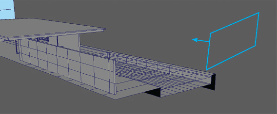
A directional light is suitable for sun light and a key light. The directional light’s translation is not important. However, its rotation is. The light’s intensity should be high enough to make the exterior of the house appear bright without overexposing it so that the textures lose detail. We want to create shadows that are relatively short to indicate the sun’s high position. The shadows should be hard-edged. That said, there can be a slight softness as natural sun light is never as hard-edged as what’s produced by 3D lights. If you are using ray trace shadows, you can increase the light’s virtual radius by a small amount (the radius property name varies in each 3D program). If you are using depth map shadows, you can adjust the shadow edge. Because the mid-day sun produces light in the blue part of the visible spectrum, we can make the light color a desaturated blue. (Too much saturation and the scene will become heavily tinted.) We can adjust the directional light until it forms an aesthetic shadow pattern and appears a suitable brightness (Figure 4.2)
“Give me the splendid silent sun with all his beams full-dazzling.”—Walt Whitman
When it comes to adding a second light as fill, there are several options
Ambient light This is easy to add as the light reaches all parts of the scene equally. However, this will illuminate parts of the model that should remain fairly dark, such as the interior ceiling or bottoms of the bench and chairs.
Directional light or spot light You can aim either of these lights to emulate bounced fill light. However, with these lights, you will have to experiment with the light rotation and translation to represent the net sum of all the light bouncing off walls and walkways.
Area light This light has the advantage of creating a soft wall of light from a particular direction. Much like directional lights and spot lights, you will have to experiment with the light rotation and translation. In addition, the scale of the light has a dramatic effect on the resulting lighting.
SIDEBAR
PBR Options
When lighting, there is always the option to use a PBR (Physically Based Rendering) lighting or rendering system. Such a system can automatically calculate bounced light, light decay, and soft shadows with a minimal effort by the lighter. However, such systems are not always practical due to lengthy rendering times. While PBR systems may produce more photorealistic results, photorealistic results may not always be the end goal of a lighting project. Hence, it is advantageous to know how to light with simpler, non-physically-based systems. We’ll discuss PBR in more detail in Chapter 5.
It’s not necessary to limit yourself to two 3D lights when recreating 2-point lighting. For example, you can use an area light and an ambient light to represent the net bounced fill light in the scene. That said, the more lights you have added to a scene, the more adjustments you will need to make to all the lights’ intensities to produce a good result. For example, adding an area light and an ambient light to the house scene requires a lower intensity for the key directional light (Figure 4.3 and 4.4). With this example, the key directional has an intensity of 2.5, the fill area light has an intensity of 1.5, and the fill ambient light has an intensity of 0.1. This creates a lighting ratio of approximately 1.6:1. With this example, shadows are also activated for the area light, although its shadow is made extremely soft.

Sunset
We’ll use the house model once again to light a sunset scene. An outdoor sunset continues to use 2-point lighting; however, different light angles, light colors, light intensities, and shadow edge qualities will help create the dim, orange-red lighting scenario we normally associate with that time of day. We can re-use the previous lights. For example, in Figure 4.5 the key directional light is rotated so that it creates longer shadows (with the rotation roughly -41, 7, -65 in XYZ). The light color is changed to a pale orange and the light intensity is reduced. The directional light shadow continues to use ray trace shadows but the light’s radius is raised to 5 world units, creating a soft shadow that degrades along the edge. The area light, serving as fill, is left in the same position; its intensity is reduced and its color is changed to pale orange. The ambient light is deactivated; due to the lower angle of the directional light, the ambient light’s contribution is no longer needed.

Candle Flame
The next scene we’ll light features a table top with a candle, as seen in Figure 4.6. The green camera icon indicates the rendering camera placement. This model is saved as candle.fbx with the exercise files.

Original 3D candle model created by monomorph, licensed via Creative Commons CC0 1.0 Universal (CC0 1.0). Original table model created by oldtimer, licensed via Creative Commons Attribution 3.0 Unported (CC BY 3.0).
We’ll begin this exercise by answering the lighting questions introduced in Chapter 3. We’ll skip to the most relevant questions
What is the location of the lighting? Interior.
What is the time of day? Night. Aside from the candle, there are no apparent light sources.
What are the properties of the light sources? This will be 1-point lighting:
A) Candle light as a key.
Before we begin lighting, we should examine the model to see if there are any caveats
Candle shader Candle wax is translucent, allowing light to scatter through its surface. Hence, the shader assigned to the candle supports translucency. The intensity, focus, and depth of the translucency is set by the shader properties; that said, the intensity is also dependent on the light intensity.
Flame effect To create a visible candle flame, special geometry or an effects simulation is necessary. With this scene, a piece of flame geometry is animated deforming over time. The geometry is assigned to an incandescent shader to make it appear as if it is a light source. An effects simulation, such as one that uses particles, would produce more realistic results.
A candle flame is an omni-directional light source emanating from the small area in space. The flame itself undulates and changes intensity over time. This produces flickering and soft-edged shadows that change shape. We can use a single point light to create this light. For example, in Figure 4.7, a point light is placed above the candle wick. The light color is set to pale orange and depth map shadows are activated and given a soft edge. To create light falloff, light decay is activated. However, instead of using a more physically-accurate quadratic equation, a linear equation is used. This allows the candle light to reach the back wall while maintaining a fairly low intensity. (For more information on light decay and decay formulas, see Chapter 3.)

In order to create a virtual flicker, the light intensity is animated randomly increasing and decreasing over time. In addition, you can animate the light icon moving a small, random distance in XYZ. This causes the shadows to shift over time (Figure 4.8).

Once again, it’s not necessary to limit the number of lights you are using to light a particular scene. With this example, a second, low-intensity ambient light is added. The ambient light contributes a small amount of brightness to areas of the frame in deep shadow, such as the base of the candle holder.
Diffuse Window Light
The next model we’ll light is an interior room, as seen in Figure 4.9. The green camera icon indicates the rendering camera placement. This model is saved as room.fbx with the exercise files. The rendering camera is named renderCamera.

Original 3D room model created by oldtimer, licensed via Creative Commons Attribution 3.0 Unported (CC BY 3.0).
Here are answers to basic questions about the scene
What is the location of the lighting? Interior.
What is the time of day? Daytime.
What are the properties of the light sources? This will be 2-point lighting:
A) Sun light scattering through an unseen window at the left side of frame serves as key.
B) Fill light in the form of sun light bounced off floors, walls, ceiling, and furniture.
Here is the caveat for the scene
Reflectivity Several shaders include reflectivity, requiring a renderer that supports ray tracing.
Area lights are well-suited to recreate sun light scattering through a window. Although sun light is virtually parallel when reaching Earth and when unobstructed, a restriction such as a door or window causes the light to scatter. The exception is the occasion when light rays are able to penetrate the room with no obstructions along the way. We’ll assume that is not the case with this exercise. The window glass, window sills, curtains, and similar obstacles cause additional scattering. As an example, an area light is placed at the left side of the model and scaled to be roughly the size of a floor-to-ceiling window (Figure 4.10). Linear light decay is activated. Once again, quadratic maybe more physically accurate, but the falloff can appear too rapid and drastic. Note that the use of light decay requires higher light intensity values than may otherwise be used. Ray trace shadows are activated. Due to the basic functionality of the area light, the shadows are soft-edged by default.
“If a window of opportunity appears, don’t pull down the shade.”—Thomas Peters

Once again, there are several routes you can take to add a secondary fill light. You can add a different light for each “wall” of bounce light. For example, you can add one light for the right-hand wall, one light for the floor, one light for the ceiling, and so on. The lights might be area lights or directional lights. Alternatively, you can add an ambient light, which reaches all points within the scene equally. A third option requires the addition of one light that represents the average of all bounced light. As such, you must find a translation and rotation that can represent the general fill light that might be present. For example, in Figure 4.11 and 4.12, a second area light is placed at the right foreground corner of the room (behind the camera). The light is pointed toward the room and is given linear light decay, ray trace shadows, and a lower intensity.


Emulating Artificial Light Sources
Artificial light sources come in many different varieties due to the technology that provides them. There are different light bulbs, such as incandescent, fluorescent, halogen, neon, HID (High Intensity Discharge), and LED. There are innumerable artificial light housings and light arrangements. Nevertheless, you can follow the same basic 3D lighting steps when tackling a scene lit by artificial lights.
Table Lamp
The first artificial light source we’ll emulate is a common table lamp, as seen in Figure 4.13. The green camera icon indicates the rendering camera placement. This model is saved as lamp.fbx with the exercise files.

Original 3D lamp model created by sizzler, licensed via Creative Commons CC0 1.0 Universal (CC0 1.0). Original room model created by oldtimer, licensed via Creative Commons Attribution 3.0 Unported (CC BY 3.0).
Here are answers to basic questions about the scene
What is the location of the lighting? Interior.
What is the time of day? Nighttime. The only visible light source is the table lamp.
What are the properties of the light sources? This will be 2-point lighting:
A) A light bulb mounted in the lamp serves as the key light. It escapes through the top and bottom of the lamp shade, forming two distinct pools of light.
B) Light scattering through the translucent shade provides fill light.
Here is the caveat for the 3D scene
Incandescent shade The lamp shade is assigned to a shader that supports incandescence. Without incandescence, the shade would appear solid and the lamp’s illumination would appear dimmer. Alternatively and more accurately, you can use a shader that supports translucency or sub-surface scattering.
There are several options for placing and adjusting a key light
Point light A point light is similar to a light bulb in that it is omni-directional. If shadows are activated, you can create shadow shapes that are appropriate for the lamp shade.
Mesh light If you use a renderer that supports custom lights based on user-selected geometry, you can create a light bulb shaped surface and have it illuminate the scene. However, mesh lights are computationally expensive to render.
Spot lights If you use two spot lights—one pointing up and one pointing down, you can quickly recreate the light pools created by a lamp shade. By using two lights, you will have greater control over their radius and orientation. In addition, the resulting shadows may be easier to refine and less render-intensive.
As seen in Figure 4.14, two spot lights are positioned within the lamp shade. The cone sizes are adjusted to glance the top and bottom openings of the shade.
The spot lights cast depth map shadows with a soft edge setting. Although depth map shadows are efficient, they may not create believable shadows at the bases of small objects, particularly when they are soft-edged. As seen in Figure 4.14, the shadows cast by the small bowl and plate are not well-defined. As an alternative, you can use ray trace shadows. In order to get a soft edge with such shadows, you must increase the light’s virtual radius (Figure 4.15). For example, when using spot lights in Autodesk Maya, you can raise the Light Radius property value. In Blender, you can raise the Soft Size value.
“You don’t have to be the brightest bulb in the house; when the darkness comes, you will be 100 watt.”—Vikrant Parsai


To create fill light scattering through the lamp shade, we can use a point light with no shadows. For example, in Figure 4.16, a point light is placed in the center of the shade. The point light is given quadratic decay with a high intensity. To prevent pure black from appearing at the lamp base and at the edges of the frame, an ambient light is also added with a low intensity. As a final step, each light is given a pale yellow color to emulate light bulbs that have a 2500 K to 2700 K color temperature, which is often found in households.

SIDEBAR
Selective Shadow Casting
Many 3D programs allow you to selectively choose what objects cast and receive shadows. In general, it’s desirable to have all surfaces in the scene cast shadows. However, in some situations, you can produce more aesthetic results by using this option. For example, with the lamp scene in this section, shadows were deactivated for the internal socket structure of the lamp model. This prevents odd-shaped shadows from appearing. Activating and deactivating shadows per surface may be less physically accurate but it can produce more attractive results.
Neon Sign
We’ll move on to a unique form of light—the neon tube, as seen in Figure 4.17. The green camera icon indicates the rendering camera placement. This model is saved as neon.fbx with the exercise files. The rendering camera is named renderCamera.
“The world, although well-lighted with fluorescents and incandescent bulbs and neon, is still full of odd dark corners and unsettling nooks and crannies.”—Stephen King

Original 3D sign model created by Bananaboy, licensed via Creative Commons CC0 1.0 Universal (CC0 1.0).
Here are answers to basic questions about the scene
What is the location of the lighting? Interior.
What is the time of day? Nighttime. The only visible light source is the neon tube.
What are the properties of the light sources? This will be 1-point lighting:
A) A twisted neon tube serves as the key light.
Here is the caveat for the 3D scene
Incandescent tube The neon tube is assigned to a shader that carries a moderate amount of incandescence. The incandescent color is red.
If you use a renderer that supports a custom mesh light, you can convert the neon tube geometry into a light source. However, it’s not always necessary to create physically-accurate lighting to generate aesthetic results. As a more efficient alternative, you can use an area light with a very soft shadow edge. For example, in Figure 4.18, an area light is placed close to the neon with a scale that’s slightly larger than the neon. Depth map shadows are activated and given an extremely soft edge. With depth map shadows, this requires a small map resolution and a large edge filter property value. The edge filter property has different names in different programs, such as Filter Size in Maya, Sample Range in 3ds Max, and Softness in Blender. The light color is set to red.
One element that is lacking is a glow. Bright light sources often appear to be glowing, whether due to light scattering through participating media such as smoke or haze or by light scattering through the optical elements of a camera. Adding a glow as an effect is a common task for 2D digital compositing. In fact, most renders created for large animation projects are processed in a compositing program as a final step, either by the lighter or by a specialized team of compositors. Some 3D programs provide shaders or shader options that create a post-process glow (a glow that’s applied on top of a rendered frame). Figure 4.19 features one such glow.


Christmas Lights
The next artificial lighting set-up we’ll work with is a string of Christmas lights, as seen in Figure 4.20. The green camera icon indicates the rendering camera placement. This model is saved as tree.fbx with the exercise files. The rendering camera is named renderCamera.

Original 3D sign model created by Mikel007, licensed via Creative Commons Attribution-ShareAlike 3.0 Unported (CC BY-SA 3.0).
Here are answers to basic questions about the scene
What is the location of the lighting? Interior.
What is the time of day? Nighttime. The only visible source of light is a string of Christmas lights.
What are the properties of the light sources? This will be 1-point lighting with multiple keys:
A) Numerous small bulbs serve as an array of key lights. Each bulb, on its own, is fairly dim.
Here is the caveat for the 3D scene
No geometry There is no geometry to represent the string of Christmas lights. However, due to the stylized nature of the tree, this is not a limitation.
To create an individual Christmas light bulb, you have several options
Point light This light type is similar to a small light bulb in that they are both omni-directional. However, the light itself will not be visible in renders. You can limit the intensity of the light by using light decay.
Volume light This light type has a specific volume (generally spherical) and a specific scale that you can set. It has a natural decay due to the limits of the volume shape. With some renderers, you can make the volume of the shape visible by activating light fog, which simulates participating media.
Advanced area light Some renderers, such as Arnold and V-Ray, support an advanced form of area light that can be made into different shapes that include discs, rectangles, and volumetric spheres. In addition, you may have the option to make the light visible in the final render.
Figure 4.21 uses a set of visible, sphere-shaped area lights. The lights use quadratic light decay and are given one of three colors. Despite the light decay, the combined light reaches the back walls. Because there is a large number of lights in the scene, depth map shadows are used with a small resolution and a soft edge quality.

Lighting a Character with Different Light Sources
Character lighting is a large portion of all 3D lighting. Hence, it’s important to emulate different light sources and make the light aesthetic when falling on a character. This applies to a wide range of characters, including photoreal, cartoon-like, human, alien, monster, and animal.
For example, we can use a cartoon-like model of a girl to emulate different natural and artificial light sources (Figure 4.22). Although the girl is not realistic, we can still apply realistic forms of lighting to help communicate the time of day and general location. We’ll begin with sun light. Here, 2-point lighting is suitable. You can place the key light to form Rembrandt, loop, butterfly, or split lighting. As demonstrated earlier, a directional light is appropriate for emulating the sun (and moon). Establishing the time of day is a matter of selecting an appropriate light rotation, light intensity, light color, and shadow edge quality (Figure 4.23, 4.24, and 4.25). The girl model is saved as girl.fbx with the exercise files. The rendering camera is named renderCamera. For additional examples of character lighting, see Chapter 6.

Original 3D sign model created by Mikel007, licensed via Creative Commons Attribution-ShareAlike 3.0 Unported (CC BY-SA 3.0).

“Light in Nature creates the movement of colors.”—Robert Delaunay


Moon light is sun light bounced from the moon’s surface. Although a blue-ish color is sometimes associated with nighttime, human vision becomes less sensitive to color at night due to the shut down of color cones in the eye. Hence, night appears desaturated and somewhat gray if there is little light.
In contrast to sun lit scenes, you can generally recreate a fire-lit scene with point lights (Figure 4.26).

In contrast to natural light sources, artificial light sources have a wider range of properties due to the many variations of artificial light design and manufacture. Nevertheless, if you can derive the light’s scale, color, focus, and shadow type, you can find a way to emulate it in 3D. For example, Figures 4.27, 4.28, 4.29, and 4.30 recreate car headlights, flashlights, flood lights, taillights, traffic lights, neon signs, and smart phone screens.
“Some of the best conversations I’ve had are sitting around a camp fire.”—Robyn Davidson


To make the headlight or floodlight scene more realistic, you can replace the standard spot light with a photometric light that has an IES file loaded. The IES file would ensure that a specific intensity and light spread appears within the light pool. IES files emulate specific light bulbs in specific bulb housings. For example, you can use an IES file for a particular type of LED flood light. For more information on IES files, see Chapter 3.
“You see but your shadow when you turn your back to the sun.” — Kahlil Gibran
SIDEBAR
Light and Shadow Linking
Many 3D programs offer the ability to make or break links between surfaces, lights, and shadows. Hence, you can choose what surfaces a light illuminates and what surfaces a light ignores. You can also choose what surfaces receive shadows and/or cast shadows. This is a convenient means to achieve aesthetic lighting without being bound to physically accurate techniques such as light decay and light bounce.

