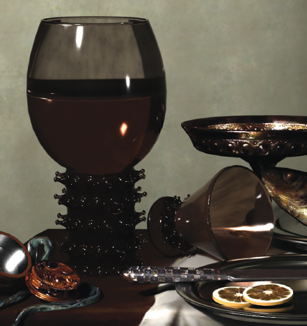
With this case study, we’ll replicate the lighting contained in a still life painting (Figure C1.1). Exercise steps are outlined for Autodesk Maya but can also serve as a general guideline for other 3D programs.
Figure C1.1 “Still life (Breakfast)” (1629) by Willem Claesz. Heda.
Public domain photo provided by The Yorck Project: 10.000 Meisterwerke der Malerei. DVD-ROM, 2002. ISBN 3936122202. Distributed by DIRECTMEDIA Publishing GmbH.
We’ll begin the exercise by answering important lighting questions introduced in Chapter 3:
What is the context of the lighting? We are matching the lighting contained in a painting as closely as possible.
What is the location of the lighting? Interior.
What is the time of day? The exact time is unclear. The reflections within the glass show a small window through which daylight arrives.
What is the time period? 1600s. There are no artificial light sources.
What are the properties of the light sources? This will be 2-point lighting:
A) Sun light as the key light. The light streams through a small window at frame left. Based on the location of the reflection, the window appears to be high on the wall. Because the light is passing through a small portal, it becomes somewhat diffuse.
B) Net reflected sun light serving as fill. The light bounces off the table and surrounding walls.
1.Launch Autodesk Maya. Open the Still-Life-Start.ma file from the Project-FilesMaya directory. Take a few minutes to familiarize yourself with the scene contents. The scene contains a mock-up of the painting (Figure C1.2). A camera named renderCamera is in position to duplicate the point-of-view of the painting. A second camera, named persp, is left as a work camera and is not intended for rendering. The model is not an exact reproduction of the painting but is close enough to duplicate the lighting. If you are not using Maya, a Still-Life-Start.fbx file is saved to the same directory.
2.Depending on the version of Maya you are running, Maya renders with either the Maya Software or Arnold renderer by default. For this section, we’ll render with the Chaos Group V-Ray renderer, which is available as a plug-in. You can download a trial copy of V-Ray at www.chaosgroup.com. After V-Ray is made available, switch the renderer to V-Ray through the Select Renderer menu at the top of the Render View window. The V-Ray renderer has a capacity for PBR rendering depending on the render options selected and whether or not V-Ray PBR shaders are employed. For this study, however, we will start with V-Ray in its default state with standard Maya materials.
3.We’ll begin the lighting process by adding a key light first. We can use an area light to replicate a small window. Choose Create > Lights > Area Light. If you are using an older version of Maya, activate ray trace shadows for the light (with recent versions, ray trace shadows are activated by default). To facilitate the adjustment of the light, go to the renderCamera viewport and select Lighting > Use All Lights and Lighting > Shadows. This shades the viewport to emulate the area light’s illumination and shadows. Set the light’s Intensity to 10 so that the shadows are easier to see. Position the light so that it sits high above the table and on the frame left side. Continue to adjust the area light translation, rotation, and scale until the shadows roughly match the shadows in the painting (Figure C1.3). Determining a translation, rotation, and scale that works well takes experimentation. Nevertheless, a Translate of −48, 60, 78, a Rotate of 347, −71, −9, and a Scale of 5, 5, 1 is suitable.
4.Test render. V-Ray launches its own variation of the Render View window, named V-Ray Frame Buffer. The renderer progressively refines the entire frame until the render is complete or the render is interrupted by the user. In addition, any changes to lights, materials, or geometry during the render causes the render to actively update the affected parts of the frame. You can press the Esc key or click the Stop button at the window ∘s upper-right corner to interrupt a render (Figure C1.4). To restart the render, press the Start Interactive Rendering at the upper-right corner of the window.
5.Switch the light’s Decay Rate from None to Quadratic. This emulates light decay in the real-world. However, the light’s Intensity must be increased significantly to affect the scene. Start with an Intensity of 250 and incrementally raise it until the table is as roughly bright as the table in the painting. It will be difficult to judge the lighting in the viewports due to the decay; thus, you must rely on the Frame Buffer window. Note that the scale of the area light also affects the required intensity—a smaller area light requires a higher Intensity value to match a larger area light. An Intensity value of 1,250 works well for an area light that is 5 world units wide and tall (Figure C1.4). An additional clue to the light’s ideal placement is the specular highlights on the objects in the scene. If the specular highlights roughly match the painting, the light’s position is fairly accurate (Figure C1.5).
6.We can now add a primary fill light. (Although we’ve determined that this is a 2-point lighting set-up, we will use more than two lights to achieve the desired look.) Choose Create > Lights > Directional Light. Rotate the light so that its illumination arrives from the opposite direction of the key light. You can scale the light icon to see it better. Scale and translation does not affect the light quality of a directional light. The new illumination is visible in the renderCamera viewport. The goal is to fill in the unlit portions of the objects. Test render. Slowly raise the new light’s Intensity until the fill lighting starts to match the painting. A rotation of roughly 64, 0, 94 is suitable (Figure C1.6). The new light starts to adds illumination to the cast shadows, making them brighter. Examining the shadow brightness helps to determine a good rotation for the directional light, although it is impossible to leave the shadows unaffected. Note that it’s not necessary to use shadows for the directional light. The directional light represents bounced light, or secondary diffuse illumination. Such illumination would create extremely soft shadows, which would be difficult to see. In the directional light’s Attribute Editor tab, deselect Use Ray Trace Shadows checkbox in the Shadows > Raytrace Shadow Attributes section (this attribute is selected by default with recent Maya versions). By the same token, it’s not necessary to create additional specular reflections on the surfaces with the fill light. Deselect the fill light’s Emit Specular checkbox (in the same section as the Color and Intensity attributes). Test render (Figure C1.7).
7.When testing, you can render regions in the V-Ray Render Buffer window by clicking the Region Render button at the top of the window so it turns blue, LMB-dragging a region box in the render area, and clicking the Start Interactive Rendering button at the top-right. To return to full-frame rendering, click the Render Region button so it is no longer blue. At this point, the back wall is missing the bright area on the left of frame. We can replicate this with a utility light. Rename the area light Key and the directional light Fill. Choose Create > Lights > Spot Light. Rename the spot light Background. You can rename a light by double-clicking the light’s name in the Outliner window (Windows > Outliner). You can scale up the spot light to better see it. Translate and rotate the light so that it illuminates the left side of the back wall. Change the light’s Cone Angle to 30 and Penumbra Angle to 7. Test render, slowly increasing the light’s Intensity until the illumination is similar to the painting (Figure C1.8). An Intensity of 2.5 works well. A Translate of −86, 73, 35 and a Rotate of −15, −34, −24 is suitable (Figure C1.9). It’s not necessary for the spot light to cast shadows. In the spot light’s Attribute Editor tab, deselect Use Ray Trace Shadows checkbox in the Shadows > Raytrace Shadow Attributes section.
8.At this phase, we can refine the shadows. One unique trait of the shadows in the painting is the dark cores and brighter, softer edges (Figure 1.10).
The only way to adjust the softness of the area light shadows is to adjust the size of the light. An alternative solution requires the addition of a second shadow-casting light that will create a darker shadow core. To do this, create a second directional light and rename it Core. Rotate the light so it points down on the table at an angle similar to the area light. If not already activated, turn on ray trace shadows for the light. Test render. The goal is to overlap the shadows of the Core light with the shadows of the Key light so there is a darker center section and a lighter edge (Figure C1.11). The core light will brighten the Key light’s shadows. Set the Intensity of the Core light to 1.5. Lower the Key light intensity to 1,000. Lower the Background light Intensity to 2. Raise the Fill light Intensity to 1.5. It’s often necessary to re-balance all the light intensities when a new light is added. To soften the edge of the Core shadows, set the Core light’s Light Angle attribute to 20; this emulates a physically broad light or light scattered through a window. Light Angle is located in the light’s Raytrace Shadow Attributes section. As for the rotation of the Core light, a value of approximately −9, 64, 125 works well.
9.At this stage, it’s worth examining the render quality. The render possesses numerous fireflies, which are misplaced or isolated pixels that appear pure white (Figure C1.12). Fireflies are often the result of strong specular reflections generated in small areas. The fireflies are particularly evident along surfaces that use bump maps, such as the silver knife and the stemmed copper dish. Advanced renderers that employ some form of path tracing offer different quality options to combat fireflies. V-Ray provides several Render Settings attributes which include Max Ray Intensity and Use Embree. Max Ray Intensity, found in the Rendering section of the Overrides tab, suppresses reflection rays that are more intense than the attribute setting. Use Embree, found in the System section of the Settings tab, activates the Intel Embree Raycaster. Embree is a collection of ray tracing kernels (processor components) optimized for photorealistic rendering. With Maya 2018, Max Ray Intensity and Use Embree are activated by default and therefore are unable to reduce the fireflies with this particular setup. Another solution calls for the use of materials/shaders designed for the renderer. For example, V-Ray includes a selection of PBR shaders that offer additional attributes for controlling reflectivity and specularity.
10.A third approach to combating fireflies calls for the adjustment of the current Maya materials. If material adjustment is permitted, as it is with this case study, you can quickly reduce fireflies by increasing the specular highlight size and reducing the specular intensity. For example, with a Blinn material, you can raise the Eccentricity value and reduce the Reflectivity, Specular Color, and Specular Roll Off values. We can improve our current render by adjusting the knife_mat and dish_mat materials (Figure C1.13). Fireflies can be difficult to remove with each scene requiring a unique solution. Additional approaches to reducing fireflies may include using renderer-centric lights or adjusting the sampling of the renderer. V-Ray supplies its own light shaders that carry their own specular contribution controls. V-Ray, like all renderers, also includes its own set of sampling controls, which we will examine later in this chapter. A matching scene file is included as Still-Life-Vray-Final.ma in the Project-FilesMaya directory.
“I have always preferred the reflection of the life to life itself.” —Francois Truffaut
The Maya scene files included with this book assume that the texture bitmaps are located in the C: Project-FilesTextures directory. If the bitmaps are not at that location when you open the file, you will need to reload the bitmaps with the following steps for each texture: open the Hypershade window (Windows > Rendering Editors > Hypershade), double-click the texture icon in the Textures tab, click the File browse button in the texture’s Attribute Editor tab, and browse for the missing texture. Missing textures receive a black icon in the Hypershade. Alternatively, if you copy the texture bitmaps to the C:Project-FilesTextures directory on your computer, simply choose File > Set Project and select the C:Project-Files directory before opening the file.
By default, Maya displays a gamma-corrected view within the Render View and V-Ray Frame Buffer windows. For these exercises, I recommend turning off the correction. In the Render View, turn off the View Transform button at the top-right of the window. In the V-Ray Frame Buffer, deactivate the Display Colors In sRgb Space button at the bottom-left of the window (see Figure C1.4). These buttons are useful when working in linear color space, where there is no gamma adjustment. However, when working in non-linear color space, as we are in this book, the extra gamma adjustment makes the render look inappropriately bright, making it difficult to judge the lighting. An alternative approach requires the deactivation of the Enable Color Management attribute in the Color Management section of the Preferences window (Windows > Settings/Preferences > Preferences). See Chapter 3 for more information on linear color space.
Figure C1.2 The Maya scene with renderCamera highlighted in green. Note that the ceiling, floor, and several walls are single-sided so that they do not block the camera or interfere with the adjustment of lights. In addition, the shadow-casting ability of those surfaces is deactivated. (If you choose to import the FBX version of this scene, you may need to deactivate the Double Side attribute once gain for those surfaces; the single-sided settings are ignored by the FBX format used for this book.)Figure C1.3 Top: The renderCamera viewport with Use All Lights and Shadows activated. The light translation, rotation, and scale is adjusted based on the resulting shadow shapes. The shadows are roughly matched to the painting. Bottom: Positioned key area light. The light is able to pass through the wall and ceiling because the ceiling and wall geometry do not cast shadows.Figure C1.4 Render with the V-Ray Frame Buffer with area light Decay Rate set to Quadratic and Intensity set to 1,250. The red arrow points to the Start Interactive Rendering and Stop Rendering buttons. The yellow arrow points to the Display Colors In sRgb Space (which is deactivated in this screen snapshot). The cyan arrow points to the Render Region button.Figure C1.5 Top: Specular reflections in painting indicated with arrows. Bottom: Specular highlight indicated in render. If the render and painting share similar specularity, then the key light translation, rotation, and scale is fairly accurate.Figure C1.6 The fill directional light arrives from a direction opposite the key area light.Figure C1.7 The addition of a fill light prevents any part of the scene from remaining pure black and adds some light to back wall.Figure C1.8 A spot light is added as a background light.Figure C1.9 Position of the spot light. The light is able to pass through the wall because the wall geometry does not cast shadows.Figure C1.10 Close-up of shadows in the painting.Figure C1.11 Render after addition of the Core directional light and re-balancing of light intensities.Figure C1.12 Enlarged view of fireflies on knife handle. Although tightly packed on this surface, fireflies may occupy a single pixel and may be isolated from other fireflies.Figure C1.13 Fireflies are greatly reduced by adjusting the specular attributes of the assigned Blinn materials.
Although renderers share many qualities, switching between renderers may produce different initial results. For example, we can switch from V-Ray to Arnold renderer in Maya. This will present its own unique set of challenges. You can follow these steps:
1.Switch the Render Using menu in the Render Settings window to Arnold Renderer. Arnold is a PBR rendering system that uses path tracing to automatically calculate light bounce. Render a test frame with the Render View window. When you switch to a different renderer, you often need to adjust the assigned materials and lights (although this may be less of an issue if the scene uses PBR shaders with texture bitmaps mapped to all the critical shader attributes). Figure C1.14 shows what the render looks like after switching to Arnold.
Here are the most significant changes:
•The light intensities are different and the scene is much darker. By default, Arnold applies quadratic light decay to spot lights and area lights and linear light decay to directional lights. Lights with low values, such as the Background light, fail to illuminate the geometry.
•Some materials behave differently. For example, the glass surfaces have lost their transparency. Bump mapping via Maya materials is not supported (when using Maya 2017 or Maya 2018).
•All lights produce specular reflections. Hence, there are additional hot spots on the glass surfaces.
•All lights in the scene cast shadows. The old shadow settings are overridden. As such, the shadow edges have changed. Arnold applies its own default shadow edge quality.
2.To fix the light balance, set the Key light Intensity to 100,000. Finding new Intensity values takes test rendering and experimentation. Set the Background light Intensity to 100,000. You can leave the Fill and Core lights set to their previous intensities. Test render (Figure C1.15).
3.To return the shadows to their prior state, you can adjust the attributes in the Arnold section of each light’s Attribute Editor tab (Figure C1.16). For example, turn off Cast Shadows for the Background and Fill lights. For the Core light, set the Angle attribute to 20 and Samples attribute to 12. Angle sets the virtual width of the light. Samples controls the shadow rendering quality. Test render (Figure C1.17).
4.Adjusting the glass and water materials is more difficult. The Arnold renderer assumes all surfaces are opaque unless otherwise designated. To designate the glass and water surfaces as non-opaque, you can follow these additional steps:
a) Open the Outliner window (Windows > Outliner). Expand the table_scene, tumbler, and goblet hierarchies. Select the tumbler_top surface. Open the Attribute Editor (Ctrl/Cmd+A). In the Arnold section of the surface’s Shape tab, deselect the Opaque checkbox.
b) Repeat this process for the tumbler_base, goblet_top, goblet_base, and water_surface surfaces.
To correct the reflectivity, specularity, and color, you can adjust the diffuse, transparency, and specular attributes of the assigned Blinn materials until the desired look is met. Another solution calls for the assignment of the glass and water surfaces to PBR shaders supported by the Arnold renderer and adjust the attributes of those shaders. For example, you can assign the surfaces to Ai Standard Surface materials in Maya. To save time, I have included example Ai Standard Surface materials with the Still-Life-Start.ma file. (If you are using Maya 2017, you will need to create your own Ai Standard materials as the Ai Standard Surface materials are not compatible.) To assign these materials, follow these steps:
a) Go to the Outliner window. Expand the table_scene, tumbler, and goblet hierarchies. Select the tumbler_base, goblet_base, and water_surface surfaces. Open the Hypershade window (Windows > Rendering Editors > Hypershade). RMB-click over the Arnold_water material and choose Assign Material To Selection from the menu.
b) Select the tumbler_top surface and assign it to the Arnold_glass material.
c) Select the goblet_top surface and assign it to the Arnold_glass2 material.
Figure C1.18 shows the render after the assignment of Arnold materials.
“We cast a shadow on something wherever we stand” —E. M. Forster
Figure C1.14 Switching to the Arnold renderer produces drastically different results.Figure C1.15 Arnold render after the adjustment of the key and background light intensities.Figure C1.16 Arnold section included in each light’s Attribute Editor tab. It’s not unusual for an advanced renderer to include its own light attributes or, alternatively, include its own renderer-centric light types.Figure C1.17 Render after the adjustment of shadows.Figure C1.18 The glass surfaces regain transparency after deselecting the surfaces’ Opaque checkbox and assigning the surfaces to Arnold Standard Surface materials.
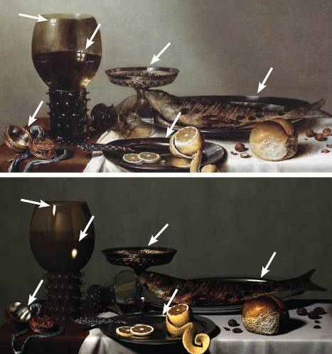
One quality of the painting that we haven’t replicated is the reflection of the window with the distinct window cross bars. There are several ways you can create this. One approach would be to construct a more accurate version of the room, complete with surrounding walls and inset window with frame and bars. With such a model, you would place the key light outside the window. Another approach requires an array of six area lights. In fact, you can duplicate and scale the current Key area light. Figure C1.19 shows such an array. Each light is given a little less than one-sixth of the original intensity (12,000). At the same time, it’s necessary to adjust the specular qualities of the materials assigned to the glass surfaces. For example, we can adjust Weight (specular strength with the attribute located in the Specular section) and Roughness (glossiness) for each assigned Arnold material. Note that each light continues to create a specular reflection. To remove the specular reflection of the Fill light, reduce the Specular attribute, in the Arnold section of the light’s Attribute Editor tab, to 0. The resulting render of lights and materials is shown in Figure C1.20.
“What difference does it make whether you’re looking at a photograph or looking at a still life in front of you? You still have to look.” —Chuck Close
Figure C1.19 The Key light is converted to an array of six smaller and weaker area lights through duplication.Figure C1.20 Window reflections are emulated by creating an array of six area lights. Path-tracing renderers, such as Arnold, are able to create accurate specular reflections of light sources.
At this point, the new window reflection has not improved the specular reflection seen in the lid of the pocket watch at the left side of the frame. Once again, a quick solution requires the adjustment of the assigned material. We can adjust the Blinn material’s Eccentricity, Specular Roll Off, Specular Color, and Reflectivity attributes. To create a more accurate reflection, you can also assign the surface to a PBR shader, such as a an Arnold Standard Surface material. If adjustment of materials/shaders is not viable for a scene, you can link a unique light to the lid surface and unlink the lid surface from pre-existing lights. As such, you can adjust the new light to improve the render quality of the watch lid without affecting any other object in the scene (see Figure C1.22 later in this section).
When the renderer was switched to Arnold, the quality of the reflections in the glass surfaces also changed. For example, the goblet has a dark reflection along its frame-right edge. This is due to the frame-left wall remaining underlit by the more aggressive light decay of the renderer. One solution is to light the wall with a separate light. For example, in Figure C1.21, an area light is pointed at the frame-left wall while avoiding other surfaces. Due to the presence of light decay, the light requires a high Intensity of 25,000. Due to the inherent light bounce of a path tracing renderer, the addition of this light contributes bounced light to the wall seen by the camera. To avoid overexposure, we can reduce each Key area light to 10,000 and the Fill light to 1.25.
Figure C1.21 Three area lights are added and pointed toward various walls. This creates more variation in the glass reflections as the surrounding room is no longer evenly lit. This also contributes to the presence of additional bounce light which requires the readjustment of the other lights in the scene.
Another element that is missing from the render is the variation of reflection brightness on the glass surfaces. For example, the goblet in the original painting has dark areas along its center. This variation is due to the painting’s reflected room possessing different degrees of light and shadow along its walls and corners. We can emulate this by adding additional area lights that point toward to the wall behind the camera (Figure C1.21). With this example, the light intensity varies between 100,000 and 150,000 for the new lights. You can adjust the resulting reflections by adjusting the light translations, rotations, and scale. Note that the strength of the reflections when using PBR materials is partially dependent on the material’s refractive index setting. For example, if the material has a relatively low refractive index, such as 1.1, the reflections are weaker. If the material has a higher refractive index, such as 1.4, the reflections are stronger. (Aside from reflectivity, refractive indexes control the amount of distortion seen within the refractions.) Hence, fine-tuning the material attributes that control refractivity, along with reflectivity, may be advantageous. With the Arnold Standard Surface material, the IOR attribute, in the Specular section, sets the refractive index. Figure C1.22 shows a render resulting from these adjustments. For more information on refractive indexes, see Chapter 3.
Figure C1.22 Render after the addition of area lights used to illuminate different parts of the surrounding room.
There is always room to improve the lighting of a 3D scene. Aside from various qualities discussed in this chapter, it’s also important to consider the render quality as set by the renderer. There are two main areas to consider with this case study: sampling and ray trace depth. Sampling refers to subpixel sampling. Every 3D renderer offers a way to increase the subpixel sampling accuracy and thus improve the render quality. The higher the subpixel sampling value, the more samples are taken per pixel. The samples take into account the geometry, materials, lights, and shadows that fall within the pixel’s domain. The higher the subpixel sampling value, the greater the number of calculations required and the longer the render takes.
The V-Ray renderer includes sampling attributes in the Image Sampler section in the VRay tab of the Render Settings window. These attributes are demonstrated in Case Study 2. The Arnold renderer includes sampling attributes in the Sampling section of the Arnold Renderer tab of the Rendering Settings window (Figure C1.23).
Arnold divides the sampling between major shading qualities, including diffuse (non-reflective), glossy (reflective), transmission (refraction), and SSS (Sub-Surface Scattering). In addition, Arnold includes a Camera (AA) attribute to control the overall anti-aliasing quality. For example, with this case study, the Camera (AA) value must be raised to remove some of the fine grain that appears along shadow edges and within reflections (Figure C1.24). When adjusting the sampling values, raise them gradually and test render with each step. Small changes to the sampling values can have a significant impact on render times.
Figure C1.23 The Sampling section of the Arnold Renderer tab of the Render Settings window.Figure C1.24 Left: Close up of bread shadow with the default sampling settings. There is a heavy grain present due to soft shadows and the placement of multiple area lights. Right: Same area rendered with Camera (AA) set to 6 and Diffuse set to 3.
In contrast, ray trace depth sets the number of times ray trace rays are permitted to bounce through a scene via reflections and refractions (transmissions). If ray trace depth is set to a small value, the render is efficient but may not be accurate as the rays may be killed off mid-way through a complex surface. For example, a low depth setting will not allow a ray to refract through the inner and outer surfaces of 3D vase. Low depth settings often create dark voids within transparent or semi-transparent surfaces.
The V-Ray renderer includes depth settings within the Materials section of the Overrides tab of the Render Settings window. The attributes include an optional Global Max Depth and Max Depth, which set the number of times a ray is allowed to reflect and/or refract before it is killed off. If Global Max Depth is left off, the renderer defers to the local depth settings of assigned materials. For example, Maya materials that support specularity include Reflection Limit and Refraction Limit attributes in the Raytrace Options section. The Vray Mtl shader includes a Depth Max attribute in the Reflection - Advanced section.
The Arnold renderer includes depth settings in the Ray Depth section of the Arnold Renderer tab of the Render Settings window. These attributes are divided and named after various shading qualities. For example, Diffuse controls the number of diffuse reflection bounces (providing secondary diffuse illumination), Specular controls the number of specular reflection bounces (providing mirror-like reflections), and Transmission sets the number of refractive bounces.
With this case study, the default depth settings produce sufficient quality. The scene in its current state was also used for the cover render (Figure C1.25 and C1.26). With the cover, the objects were rearranged but the lighting was left intact. The final V-Ray scene is included in the Project-FilesMaya directory as Still-Life-Vray-Final.ma. The final Arnold scene is included in the Project-FilesMaya directory as Still-Life-Arnold-Final.ma.
Throughout these case studies, I provide values for various attributes, such as light colors, light intensities, and shadow qualities. These values were determined through experimentation. In other words, I wasn’t able to derive the values without trying a wider range of values and test rendering. Experimentation is a necessary part of 3D lighting. A render rarely turns out perfect on the first try. At the same time, you should remain flexible enough to re-adjust the values as you proceed to add additional lights, shadows, and lighting effects.
Figure C1.25 The objects are rearranged to create the cover render.Figure C1.26 The cover render. The grayscale insert was created by temporarily assigning all the surfaces to a gray Lambert material and using a low Camera (AA) value to intentionally create noise. The color insert is a screen snapshot of the renderCamera with Hardware Texturing activated.