
6
CHAPTER
Resistors
ALL ELECTRICAL COMPONENTS, DEVICES, AND SYSTEMS EXHIBIT RESISTANCE. IN PRACTICE, PERFECT conductors don’t exist. You’ve seen some examples of circuits containing components designed to reduce or limit the current. We call these components resistors.
Purpose of the Resistor
Resistors play diverse roles in electrical and electronic equipment, despite the fact that their only direct action constitutes interference with the flow of current. Common applications include the following:
• Voltage division
• Biasing
• Current limiting
• Power dissipation
• Bleeding off charge
• Impedance matching
Voltage Division
You’ve learned how to build voltage dividers using resistors. The resistors dissipate some power in doing this job, but the resulting potential differences ensure that an external circuit or system operates properly. For example, a well-engineered voltage divider allows an amplifier to function efficiently, reliably, and with a minimum of distortion.
Biasing
In a bipolar transistor, a field-effect transistor, or an electron tube, the term bias means that we deliberately apply a certain DC voltage to one electrode relative to another, or relative to electrical ground. Networks of resistors can accomplish this function.
A radio transmitting amplifier works with a different bias than an oscillator or a low-level receiving amplifier. Sometimes we must build low-resistance voltage dividers to bias a tube or transistor; in some cases a single resistor will do.
Figure 6-1 shows a bipolar transistor that obtains its bias from a pair of resistors in a voltage-divider configuration. We’ll learn about the transistor electrodes, called the emitter (E), the base (B), and the collector (C), later in this course.

6-1 A pair of resistors can act as a voltage divider in a transistor circuit.
Current Limiting
A sensitive amplifier designed for radio reception offers a good example of an application in which a current-limiting resistor in series with the power-supply or battery output keeps the transistor from dissipating too much power as heat. Without such a resistor to limit or control the current, the transistor would carry a lot of DC that wouldn’t contribute to the signal amplification process, and might actually degrade it.
Figure 6-2 shows a current-limiting resistor connected between the emitter of a bipolar transistor and electrical ground, which also constitutes the negative power-supply connection (not shown). We can supply the signal input across that resistor (between E and ground) or at the base of the transistor (B). We would normally take the signal output from the collector (C).

6-2 A resistor between the emitter and ground limits the current through a transistor.
Power Dissipation
In some applications, we want a resistor to dissipate power as heat. Such a resistor might constitute a “dummy” component, so that a circuit “sees” the resistor mimic the behavior of something more complicated.
When testing a radio transmitter, for example, we can install a massive resistor in place of the antenna (Fig. 6-3). This engineering trick allows us to test the transmitter for long periods at high power levels without interfering with on-the-air communications. The transmitter output heats the resistor without radiating any signal. However, the transmitter “sees” the resistor as if it were a real antenna—and a perfect one, too, if the resistor has the correct ohmic value.

6-3 At A, a radio transmitter connected to a real antenna. At B, the same transmitter connected to a resistive “dummy” antenna.
We might take advantage of a resistor’s power-dissipating ability at the input of a power amplifier, such as the sort used in hi-fi audio equipment. Sometimes the circuit driving the amplifier (supplying its input signal) produces too much power. A resistor, or network of resistors, can dissipate the excess power so that the amplifier doesn’t receive too much input signal. In any type of amplifier, overdrive (an excessively strong input signal) can cause distortion, inefficiency, and other problems.
Bleeding Off Charge
A high-voltage, DC power supply employs capacitors (sometimes along with other components) to smooth out the current pulsations, known as ripple. These filter capacitors acquire an electric charge and store it for a while. In some power supplies, filter capacitors can hold the full output voltage of the supply, say something like 750 V, for a long time even after we power the whole system down. Anyone who attempts to repair or test such a power supply can receive a deadly shock from this voltage.
If we connect a bleeder resistor in parallel with each individual filter capacitor in a power supply, the resistors will drain the capacitors’ stored charge, sparing personnel who service or test the power supply the risk of electrocution. In Fig. 6-4, the bleeder resistor R should have a value high enough so that it doesn’t interfere with the operation of the power supply, but low enough so that it will discharge the capacitor C in a short time after power-down.

6-4 A bleeder resistor (R) connected across the filter capacitor (C) in a power supply.
Even if a power supply has bleeder resistors installed, the wise engineer or technician, wearing heavy, insulated gloves, will short out all filter capacitors, using a screwdriver or other metal tool with an insulated handle, after power-down and before working on the circuit. Even if the supply has bleeder resistors, they can take awhile to get rid of the residual charge. Besides that, bleeder resistors sometimes fail!
Impedance Matching
We encounter a more sophisticated application for resistors in the coupling between two amplifiers, or in the input and output circuits of amplifiers. In order to produce the greatest possible amplification, the impedances between the output of a given amplifier and the input of the next must precisely agree. The same holds true between a source of signal and the input of an amplifier. The principle also applies between the output of an amplifier and a load, whether that load is a speaker, a headset, or whatever. We might think of impedance as the AC “big brother” of DC resistance. You’ll learn about impedance in Part 2 of this book.
Fixed Resistors
In your engineering adventures, you’ll encounter fixed resistors (units whose resistance never changes) in several different geometries and modes of construction.
Carbon-Composition Resistors
The cheapest method of making a resistor involves mixing powdered carbon (a fair electrical conductor) with a nonconductive solid or paste, pressing the resulting clay-like “goo” into a cylindrical shape, inserting wire leads in the ends, and then letting the whole mass harden (Fig. 6-5). The resistance of the final product depends on the ratio of carbon to the nonconducting material, and also on the physical distance between the wire leads. This process yields a carbon-composition resistor.
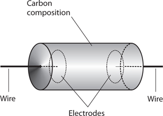
6-5 Construction of a carbon-composition resistor.
You’ll find carbon-composition resistors in a wide range of ohmic values. This kind of resistor is nonreactive, meaning that it introduces almost pure resistance into the circuit, and essentially no inductive reactance or capacitive reactance. (You’ll learn more about both types of reactance later in this book.) This property makes carbon-composition resistors useful in the construction of radio receivers and transmitters, where the slightest extraneous reactance can cause trouble.
Carbon-composition resistors dissipate power in proportion to their physical size and mass. Most of the carbon-composition resistors you see in electronics stores can handle ¼ W or ½ W. You can also find ⅛ W units for use in miniaturized, low-power circuitry, and 1 W or 2 W units for circuits that require electrical ruggedness. Occasionally, you’ll see a carbon-composition resistor with a power rating, such as 50 or 60 W, but not often.
Wirewound Resistors
We can also obtain resistance with a length of wire made from poorly conducting material. The wire can take the form of a coil wound around a cylindrical form, as shown in Fig. 6-6. The resistance depends on how well the wire conducts, on its diameter or gauge, and on its total stretched-out length. When we construct a component in this fashion, we have a wirewound resistor.

6-6 Construction of a wirewound resistor.
Wirewound resistors usually have low to moderate values of resistance. You’ll find wirewound resistors whose ohmic values fall within a very narrow range, sometimes a fraction of 1 percent either way of the quoted value. We say that such components have close tolerance or tight tolerance. Some wirewound resistors can handle large amounts of power. That’s their best asset. On the downside, wirewound resistors always exhibit some inductive reactance because of their coiled geometry, making them a poor choice for use in situations where high-frequency AC or radio-frequency (RF) current flows.
Film-Type Resistors
We can apply carbon paste, resistive wire, or some mixture of ceramic and metal to a cylindrical form as a film, or thin layer, to obtain a specific resistance. When we do this, we get a carbon-film resistor or metal-film resistor. Superficially, the component looks like a carbon-composition resistor, but the construction differs (Fig. 6-7).

6-7 Construction of a film-type resistor.
The cylindrical form consists of an insulating substance, such as porcelain, glass, or thermoplastic. The film can be deposited on this form by various methods, and the value tailored as desired. Metal-film resistors can be manufactured to extremely close tolerances. Film-type resistors usually have low to medium-high resistance.
Film-type resistors, like carbon-composition resistors, have little or no inductive reactance—a big asset in high-frequency AC applications. However, film-type resistors generally can’t handle as much power as carbon-composition or wirewound types of comparable physical size.
Integrated-Circuit (IC) Resistors
A semiconductor wafer known as an integrated circuit (IC), also called a chip, allows for the fabrication of resistors on its surface. The thickness of the resistive layer, and the types and concentrations of impurities added, determine the resistance of the component. Because of its microscopic size, a typical IC resistor can handle only a tiny amount of power. However, this limitation rarely poses a problem because the entire circuit on the chip functions at nanopower levels (on the order of nanowatts, units of 10−9 W) or micropower levels (on the order of microwatts, units of 10−6 W).
The Potentiometer
Figure 6-8A illustrates the construction geometry of a potentiometer, which acts as a variable resistor. Figure 6-8B shows the schematic symbol. A resistive strip, similar to that found on film-type fixed resistors, forms approximately ¾ of a circle (an arc of 270°), with terminals connected to either end. This strip exhibits a fixed value of resistance. To obtain the variable resistance, a sliding contact, attached to a rotatable shaft and bearing, goes to a third (middle) terminal. The resistance between the middle terminal and either end terminal can vary from zero up to the resistance of the whole strip. Most potentiometers can handle only low levels of current, at low to moderate voltages. You’ll encounter two major designs in your electronics work: the linear-taper potentiometer and the audio-taper potentiometer.

6-8 Simplified functional drawing of a rotary potentiometer (A), and the schematic symbol (B).
Linear-Taper Potentiometer
A linear-taper potentiometer uses a strip of resistive material with constant density all the way around. As a result, the resistance between the center terminal and either end terminal changes at a steady rate as the control shaft rotates. Engineers usually prefer linear-taper potentiometers in electronic test instruments. Linear-taper potentiometers also exist in some consumer electronic devices.
Suppose that a linear-taper potentiometer has a value of 0 to 270 ohms. In most units, the shaft rotates through a total angular displacement of about 270°. The resistance between the center and one end terminal increases along with the number of angular degrees that the shaft turns away from that end terminal. The resistance between the center and the other end terminal equals 270 minus the number of degrees that the control shaft subtends with respect to that terminal. The resistance between the middle terminal and either end terminal, therefore, constitutes a linear function of the angular shaft position.
Audio-Taper Potentiometer
In some applications, linear taper potentiometers don’t work well. The volume control of a radio receiver or hi-fi audio amplifier provides a good example. Humans perceive sound intensity according to the logarithm of the actual sound power, not in direct proportion to the actual power. If you use a linear-taper potentiometer to control the volume (or gain) of a radio receiver or audio system, the sound volume (as you hear it) will change slowly in some parts of the control range, and rapidly in other parts of the control range. The device will work, but not in a user-friendly fashion.
An audio-taper potentiometer, if properly selected and correctly installed, can compensate for the way in which people perceive sound levels. The resistance between the center and either end terminal varies according to a nonlinear function of the angular shaft position. Some engineers call this type of device a logarithmic-taper potentiometer or log-taper potentiometer because the function of resistance versus angular displacement follows a logarithmic curve. As you turn the shaft, the sound intensity seems to increase in a linear manner, even though the actual power variation is logarithmic.
Slide Potentiometer
A potentiometer can employ a straight strip of resistive material rather than a circular strip so that the control moves up and down, or from side to side, in a straight line. This type of variable resistor, called a slide potentiometer, finds applications in hi-fi audio graphic equalizers, as gain controls in some amplifiers, and in other applications where operators prefer a straight-line control movement to a rotating control movement. Slide potentiometers exist in both linear-taper and audio-taper configurations.
Rheostat
A variable resistor can employ a wirewound element, rather than a solid strip of resistive material. We call this type of device a rheostat. It can have either a rotary control or a sliding control, depending on whether the resistive wire is wound around a donut-shaped form (toroid) or a cylindrical form (solenoid). Rheostats exhibit inductive reactance as well as resistance. They share the advantages and disadvantages of fixed wirewound resistors.
We can’t adjust a rheostat in a perfectly smooth “continuum” as we can do with a potentiometer because the movable contact slides along the wire coil from a certain point on one turn to the adjacent point on the next turn. The smallest possible increment of resistance therefore equals the amount of resistance in one turn of the coil.
Rheostats find applications in heavy-duty systems, such as variable-voltage power supplies, designed for use with electron-tube amplifiers. This kind of supply contains a massive AC transformer that steps up the voltage from the 117 V utility mains. A rectifier circuit converts the AC to DC. The rheostat is usually placed between the utility outlet and the transformer, as shown in Fig. 6-9, providing adjustable DC voltage at the power-supply output.

6-9 Connection of a rheostat in a variable-voltage power supply.
The Decibel
As stated in the preceding paragraphs, perceived levels of sound change according to the logarithm of the actual sound power level. Engineers and technicians use decibels (symbolized dB) to express relative perceived sound-power levels. Sound-power decibels get along naturally with the use of audio-taper potentiometers for volume control.
Decibels in Terms of Power
One decibel (1 dB) represents the smallest sudden increase or decrease in sound power that you can detect, if you anticipate an imminent change. Positive decibel values represent power increases. Negative decibel values represent power decreases. If you do not anticipate an imminent change in the sound power and then it increases or decreases suddenly, you won’t notice the fluctuation unless the difference amounts to at least +3 dB or −3 dB.
Changes in intensity, when expressed in decibels, are sometimes called gain and loss. Positive decibel changes represent gain, and negative decibel changes represent loss. You can omit the sign (plus or minus) when speaking of changes in terms of decibel gain or decibel loss because the words “gain” and “loss” imply the sign. If you say that a certain system causes 5 dB of sound-power loss, for example, you indicate that the circuit produces a sound-power change of −5 dB.
We calculate sound-power decibel values according to the logarithm of the ratio of change. Imagine that an acoustic disturbance produces P watts of power when it strikes your eardrums, and then the power increases or decreases to Q watts. To calculate the extent of the change in decibels, we use the formula
dB = 10 log (Q/P)
where “log” stands for the base-10 logarithm.
As an example, suppose that a speaker emits 1 W of sound power, and then we turn up the gain so that the speaker emits 2 W of sound power. In this case, we have P = 1 and Q = 2, so
dB = 10 log (2/1) = 10 log 2 = 10 × 0.3 = +3 dB
If we turn the system gain back down so that the speaker once again emits only 1 W of sound power, then we get P/Q = 1/2 = 0.5, and we can calculate
dB = 10 log (1/2) = 10 × (−0.3) = −3 dB
A gain or loss of 10 dB (a change of +10 dB or −10 dB, often shortened to ±10 dB) represents a 10-fold increase or decrease in sound power. A change of ±20 dB represents a 100-fold increase or decrease in power. You’ll occasionally encounter sounds that vary in intensity over ranges of ±90 dB, which represents a thousand-million-fold increase or decrease in power—from a microwatt to a kilowatt, for example!
Power in Terms of Decibels
We can work the above-defined formula inside-out to determine the final sound power, given the initial power and the decibel change. To do this, we use the inverse of the base-10 logarithmic function, symbolized as log−1, or antilog. Any good scientific calculator can execute both the log and antilog functions.
Suppose that we have a sound of initial power P, and then it changes by x dB. We can find the final sound power Q using the formula
Q = P antilog (x/10)
Consider an acoustic disturbance whose initial power equals 10 W, and then we perceive or measure a sudden level change of x = −3 dB. We can calculate the final sound power Q as
Q = 10 antilog (−3/10) = 10 antilog (−0.3) = 10 × 0.5 = 5 W
“Absolute” Decibels
We can specify “absolute” sound-power levels in decibels relative to the threshold of hearing, defined as the faintest possible acoustic disturbance that a person with normal hearing can detect in a quiet room. We assign a value of 0 dB to sounds at this threshold. We can then quantify the intensities of other sounds as figures, such as 30 dB or 75 dB.
If a certain noise has a loudness of 30 dB, that means it’s 30 dB above the threshold of hearing, or 1000 times as loud (in terms of power) as the quietest detectable noise. A noise at 60 dB is 1,000,000 (or 106) times as powerful as a sound at the threshold of hearing. Sound-level meters can accurately determine and display the decibel levels of various noises and acoustic environments.
A typical conversation between two people a couple of meters apart occurs at a level of about 70 dB. This level represents 10,000,000 (or 107) times the threshold of hearing in terms of actual sound power. The roar of the crowd at a country-music concert might be 90 dB, or 1,000,000,000 (109) times the threshold of hearing. The 100-dB shriek of a tornado-warning siren a few meters away from your ears represents 10,000,000,000 (1010) times the power contained in a whisper at the threshold of hearing.
Resistor Specifications
When we select a resistor for a particular application, we must obtain a unit that has the correct properties, or specifications. Here are some of the most important specifications to watch for.
Ohmic Value
In theory, a resistor can have any ohmic value from the lowest possible (such as a shaft of solid silver) to the highest (dry air). In practice, we’ll rarely find resistors with values less than about 0.1 ohm or more than about 100 M.
Resistors are manufactured with ohmic values in power-of-10 multiples of numbers from the set
{1.0, 1.2, 1.5, 1.8, 2.2, 2.7, 3.3, 3.9, 4.7, 5.6, 6.8, 8.2}
We’ll routinely see resistances such as 47 ohms, 180 ohms, 6.8 k, or 18 M, but we’ll hardly ever find resistors with values such as 384 ohms, 4.54 k, or 7.297 M.
Additional basic resistances exist, intended especially for tight-tolerance (or precision) resistors: power-of-10 multiples of numbers from the set
{1.1, 1.3, 1.6, 2.0, 2.4, 3.0, 3.6, 4.3, 5.1, 6.2, 7.5, 9.1}
Tolerance
The first set of numbers above represents standard resistance values available in tolerances of plus or minus 10 percent (±10%). This means that the resistance might be as much as 10% more or less than the indicated amount. In the case of a 470-ohm resistor, for example, the value can be larger or smaller than the rated value by as much as 47 ohms, and still adhere to the rated tolerance. That’s a range of 423 to 517 ohms.
Engineers calculate resistor tolerance figures on the basis of the rated resistance, not the measured resistance. For example, we might test a “470-ohm” resistor and find it to have an actual resistance of 427 ohms; this discrepancy would still put the component within ±10% of the specified value. But if we test it and find it to have a resistance of 420 ohms, its actual value falls outside the rated range, so it constitutes a “reject.”
The second set of numbers listed above, along with the first set, represents all standard resistance values available in tolerances of plus or minus 5 percent (±5%). A 470-ohm, 5% resistor will have an actual value of 470 ohms plus or minus 24 ohms, or a range of 446 to 494 ohms.
For applications requiring exceptional precision, resistors exist that boast tolerances tighter than ±5%. We might need a resistor of such quality in a circuit or system where a small error can make a big difference. In most audio and RF oscillators and amplifiers, we’ll usually do okay with resistors having ±10% or ±5% tolerances. In some applications, we can even get away with a ±20% tolerance.
Power Rating
A manufactured resistor always bears a specification that tells us how much power it can safely dissipate. The dissipation rating indicates continuous duty, which means that the component can dissipate a certain amount of power constantly and indefinitely.
We can calculate how much current a given resistor can handle using the formula for power P (in watts) in terms of current I (in amperes) and resistance R (in ohms), as follows:
P = I2R
With algebra, we can change this formula to express the maximum allowable current in terms of the power dissipation rating and the resistance, as follows:
I = (P/R)1/2
where the ½ power represents the positive square root.
We can effectively multiply the power rating for a given resistor by connecting identical units in series-parallel matrices of 2 × 2, 3 × 3, 4 × 4, or larger. If we need a 47-ohm, 45-W resistor but we have only a lot of 47-ohm, 1-W resistors available, we can connect seven sets of seven resistors in parallel (a 7 × 7 series-parallel matrix) and get a 47-ohm resistive component that can handle up to 7 × 7 W, or 49 W.
Resistor power dissipation ratings, like the ohmic values, are specified with a margin for error. A good engineer never tries to “push the rating” and use, say, a ¼-W resistor in a situation where it will need to draw 0.27 W. In fact, good engineers usually include their own safety margin, in addition to that offered by the vendor. Allowing a 10% safety margin, for example, we should never demand that a ¼-W resistor handle more than about 0.225 W, or expect a 1-W resistor to dissipate more than roughly 0.9 W.
Temperature Compensation
All resistors change value when the temperature rises or falls dramatically. Because resistors dissipate power by design, they get hot in operation. Sometimes the current that flows through a resistor does not rise high enough to appreciably heat the component. But in some cases it does, and the heat can cause the resistance to change. If this effect becomes great enough, a sensitive circuit will behave differently than it did when the resistor was still cool. In the worst-case scenario, an entire device or system can shut down because of a single “temperamental” resistor.
Resistor manufacturers do various things to prevent problems caused by resistors changing value when they get hot. In one scheme, resistors are specially manufactured so that they don’t appreciably change value when they heat up. We call these components temperature compensated. As you might expect, a temperature-compensated resistor can cost several times as much as an ordinary resistor.
Rather than buy a single temperature-compensated resistor, we can employ a single resistor or a series-parallel matrix of resistors with a power rating several times higher than we ever expect the component to dissipate. This technique, called over-engineering, keeps the resistor or matrix from reaching temperatures high enough to significantly change the resistance. Alternatively, we might take several resistors, say five of them, each with five times the intended resistance, and connect them all in parallel. Or we can take several resistors, say four of them, each with about ¼ of the intended resistance, and connect them in series.
Whatever trick we employ to increase the power-handling capability of a component, we should never combine resistors with different ohmic values or power ratings into a single matrix. If we try that, then one of them might end up taking most of the load while the others “loaf,” and the combination will perform no better than the single hot resistor we started with. Whenever we want to build a “resistor gang” to handle high current or keep cool under load, we should always procure a set of identical components.
Are You Astute?
You might ask, “If we want to build our own temperature-compensated resistor, can we use two resistors with half (or twice) the value we need, but with opposite resistance-versus-temperature characteristics, and connect them in series or parallel?” That’s an excellent question. If we can find two such resistors, the component whose resistance decreases with increasing temperature (that is, the one that has a negative temperature coefficient) will partially or totally “undo” the thermal problem caused by the component whose resistance goes up with increasing temperature (the one that has a positive temperature coefficient). This scheme can sometimes work. Unfortunately, we’d likely spend more time trying to find two “ideally mismatched” resistors than we’d spend by resorting to “brute force” and building a series-parallel matrix.
The Color Code for Resistors
Some resistors have color bands that indicate their values and tolerances. You’ll see three, four, or five bands around carbon-composition resistors and film resistors. Other resistors have enough physical bulk to allow for printed numbers that tell us the values and tolerances straightaway.
On resistors with axial leads (wires that come straight out of both ends), the first, second, third, fourth, and fifth bands are arranged as shown in Fig. 6-10A. On resistors with radial leads (wires that come off the ends at right angles to the axis of the component body), the colored regions are arranged as shown in Fig. 6-10B. The first two regions represent single digits 0 through 9, and the third region represents a multiplier of 10 to some power. (For the moment, don’t worry about the fourth and fifth regions.) Table 6-1 indicates the numerals corresponding to various colors.

6-10 At A, locations of color-code bands on a resistor with axial leads. At B, locations of color code designators on a resistor with radial leads.
Table 6-1. Color code for the first three bands on fixed resistors. See text for discussion of the fourth and fifth bands.

Suppose that you find a resistor with three bands: yellow, violet, and red, in that order. You can read as follows, from left to right, referring to Table 6-1:
• Yellow = 4
• Violet = 7
• Red = ×100
You conclude that the rated resistance equals 4700 ohms, or 4.7 k. As another example, suppose you find a resistor with bands of blue, gray, and orange. You refer to Table 6-1 and determine that
• Blue = 6
• Gray = 8
• Orange = ×1000
This sequence tells you that the resistor is rated at 68,000 ohms, or 68 k.
If a resistor has a fourth colored band on its surface (#4 as shown in Fig. 6-10 A or B), then that band tells you the tolerance. A silver band indicates ±10%. A gold band indicates ±5%. If no fourth band exists, then the tolerance is ±20%.
The fifth band, if any, indicates the maximum percentage by which you should expect the resistance to change after the first 1000 hours of use. A brown band indicates a maximum change of ±1% of the rated value. A red band indicates ±0.1%. An orange band indicates ±0.01%. A yellow band indicates ±0.001%. If the resistor lacks a fifth band, it tells you that the resistor might deviate by more than ±1% of the rated value after the first 1000 hours of use.
A savvy engineer or technician always tests a resistor with an ohmmeter before installing it in a circuit. If the component turns out defective or mislabeled, you can prevent potential future headaches by following this simple precaution. It takes only a few seconds to check a resistor’s ohmic value. In contrast, once you’ve finished building a circuit and discover that it won’t work because of some miscreant resistor, the troubleshooting process can take hours.
Quiz
Refer to the text in this chapter if necessary. A good score is at least 18 correct. Answers are in the back of the book.
1. As a repair technician, if you want to keep high-voltage, power-supply filter capacitors from electrocuting you after you switch off the supply, but not let them interfere with the supply’s performance when it’s powered up, what should you do?
(a) Wait 10 minutes after powering-down before you begin work.
(b) Permanently short circuit all the filter capacitors.
(c) Install inductors in series with all the capacitors.
(d) None of the above
2. You have a package of resistors, all rated at 330 ohms ±10%. You test three of them with an ohmmeter, obtaining the readings in (a), (b), and (c) below. Which, if any, of these tested values lies outside the tolerance range, telling you that the component is a reject?
(a) 299 ohms
(b) 305 ohms
(c) 362 ohms
(d) They’re all okay
3. Which of the following resistor types is a good choice for use in a circuit designed to operate at 14 MHz?
(a) Carbon-composition
(b) Carbon-film
(c) Integrated-circuit
(d) Any of the above
4. A musical note from your hi-fi system comes out at “20 dB.” In terms of sound power, how does this volume level compare with the threshold of hearing?
(a) It’s twice as powerful.
(b) It’s 20 times as powerful.
(c) It’s 100 times as powerful.
(d) None of the above! Decibels express frequency, not power.
5. The working part of a “dummy” antenna is
(a) an inductor.
(b) a resistor.
(c) a capacitor.
(d) a short circuit.
6. In the schematic diagram for a transistorized amplifier, you see a resistor between the base and ground, and another resistor between the base and the positive battery terminal. What purpose do these resistors serve if you choose their values correctly?
(a) They maximize the current that flows through the transistor.
(b) They bleed off any excess charge that might exist on the base.
(c) They optimize the bias at the base.
(d) They keep the transistor from shorting out.
7. A resistor has three colored bands, going from left to right in this order: green, red, brown. As rated by the manufacturer, its resistance is close to
(a) 68 ohms.
(b) 520 ohms.
(c) 8.2 k.
(d) 18 k.
8. The most common way to limit the current through a transistor is to connect a resistor between the
(a) collector and emitter.
(b) base and collector.
(c) emitter and ground.
(d) collector and ground.
9. In which of the following situations should we expect a 200-W wirewound resistor to work well?
(a) In series with the emitter of a high-power RF amplifier transistor, for the purpose of current limiting
(b) In series with the collector of a low-power RF amplifier transistor, for the purpose of voltage limiting
(c) In series with the filter capacitor in a power supply, for the purpose of minimizing the output ripple
(d) In any DC circuit needing a resistor that can dissipate far more power than a carbon-based resistor can do
10. A 470-ohm resistor carries 15 mA continuously. What resistor power rating is sufficient, but not needlessly high?
(a) ¼ W
(b) 1 W
(c) 2 W
(d) 5 W
11. How much voltage (rounded to two significant figures) appears across the resistor described in Question 10?
(a) 0.15 V
(b) 7.1 V
(c) 10 V
(d) 70 V
12. You find a resistor with a manufacturer’s rated value of 470 ohms. You measure its resistance as 490 ohms. What’s the percentage difference between the measured value and the manufacturer’s rated value?
(a) +4.08%
(b) +4.26%
(c) −4.08%
(d) −4.26%
13. In an audio-taper potentiometer, the resistance varies in proportion to the
(a) angular shaft displacement.
(b) logarithm of the angular shaft displacement.
(c) square of the angular shaft displacement.
(d) square root of the angular shaft displacement.
14. Refer to Fig. 6-4. You connect this circuit in a DC power supply designed to provide 800 V DC. If you properly choose the resistor’s ohmic value, it can
(a) reduce the chance that a repair technician will get killed.
(b) prevent capacitor C from shorting out or opening up.
(c) maximize the efficiency of the power supply as a whole.
(d) eliminate the output ripple whether the capacitor works or not.
15. A rheostat contains, among other things,
(a) a coil of wire.
(b) carbon paste.
(c) carbon film.
(d) Any of the above
16. A carbon-composition resistor has the following colored bands: red, red, red, silver. What’s its resistance as rated by the manufacturer?
(a) 22 ohms ±10%
(b) 220 ohms ±10%
(c) 2.2 k ±10%
(d) 22 k ±10%
17. Which, if any, of the following characteristics describes an advantage of a potentiometer over a rheostat?
(a) A potentiometer has reactance, but a rheostat lacks reactance and, therefore, won’t work well in AC applications.
(b) A potentiometer works well at DC, but a rheostat doesn’t because it has too much reactance.
(c) A potentiometer can work in high-voltage, high-current applications, but a rheostat can’t.
(d) None of the above
18. For the volume control in an audio amplifier, you would get the best results with a
(a) log-taper potentiometer.
(b) linear-taper potentiometer.
(c) wirewound resistor.
(d) rheostat.
19. If you want to build a graphic equalizer for your hi-fi system, you would probably want to use
(a) rheostats.
(b) voltage dividers.
(c) slide potentiometers.
(d) rotary potentiometers.
20. Which of the following resistor types has minimal reactance?
(a) carbon-composition
(b) rheostat
(c) wirewound
(d) capacitive