
CHAPTER 4
ATTRIBUTES OF EM POLARIZERS
4.1 INTRODUCTION
Electromagnetic (EM) polarizers were introduced in Chapter 3. The edge diffraction of the proposed polarizer and its antenna mode result in significant cross-polar components in the backscattered direction, which provides the basis for the data encoding in a chipless RFID system. In this chapter, the fabricated polarizers through the photolithographic process and printing technique are tested in laboratory environment. When the depolarization aspect of the suggested structure as polarizer is confirmed, then the cross-polarized working basis is reviewed in more detail. First, the equivalent system model is introduced to ease the network analysis of the proposed cross-polarized system. The effectiveness of the system for unwanted reflections is proved mathematically. Then, different measurement scenarios are considered to investigate the system robustness in various scenarios. The effect of reflections from other objects and multipath interferences are also considered in the measurement process. This finding suggests huge advantages of the EM-polarizer-based system for industrial environments. Moreover, the polarizer-based tag is shown to be very efficient for tagging of highly reflective items; water bottles or metallic cans, for example. The bending effect of the tag conformal to various types of objects, on its cross-polar performance, is also considered in this chapter. Finally, the effect of barriers on the system performance is investigated and shows an interesting aspect for the suggested technique, hidden tag-reading capability.
4.2 SUGGESTED STRUCTURES AS EFFECTIVE EM POLARIZERS
Two structures, strip lines and meander lines, were suggested as EM polarizers and their performance was confirmed through simulation. It is beneficial now to validate their performance as polarizer in real scenario. For this purpose, a suitable measurement setup is required to maintain the cross-polar working basis.
The system setup for the measurement process is shown in Figure 4.1. On the reader side, two antennas are used. Antennas are double-side-printed dipoles (DSPDs) that have been designed to cover the whole suggested frequency band 57–64 GHz. They are very small and so are easily movable, due to the requirement for synthetic aperture radar (SAR). The main aspects of the antennas are their high axial ratios or equivalently low cross-polar level. This is vital for the cross-polar-based system. Moreover, antennas have a wide azimuth beamwidth that is required to interrogate the tag surface from different view angles. The design parameters and procedures of the antenna are discussed later. For measurement purposes, antennas are oriented orthogonally and they are connected to the performance network analyzer (PNA). Considering the low cross-polar level of the designed antennas and their orthogonal orientation, a very low signal leakage between transmit (Tx) and receive (Rx) antenna is expected. A plastic pole is installed in front of the antennas on which the tag is attached. The PNA's transmit power is −5 dBm, that is, its maximum power at the millimeter-band of 60 GHz. Due to the limitation of the PNA transmit power, the reading distance is set to 10 cm. It will be shown that the average gain of the antenna is 5.5–7 dBi, hence the maximum equivalent isotropically radiated power (EIRP) used in this measurement setup is only +0.5–2 dBm. As shown in Chapter 5, the maximum allowable EIRP at the suggested band is +40 dBm; hence, the reading distance in the proposed technique would increase up to 50 cm if adequate transmitter is available. The PNA measures the S-parameters versus frequency; hence, cross-RCS of the tag in dBm versus frequency is shown by the PNA.

Figure 4.1 System measurement setup: (a) printed strip lines, (b) printed meander lines, (c) whole system, and (d) reader antenna.
4.2.1 Precise Polarizers
The fabricated tags through photolithographic process that have been introduced in Chapter 3 are attached to the pole for measurement purposes. The S21 in decibel versus frequency is shown in Figure 4.2. The dashed line shows the S21 when no tag is attached to the pole. The signal level is below −65 dBm. This presents the amount of signal leakage and mutual coupling between the two orthogonally polarized antennas as well as the effect of the plastic pole. The very low signal level is not unusual as the antennas are oriented orthogonally and each antenna has a low cross-polar level.

Figure 4.2 Measurement result for photolithographic fabricated tags.
Attaching a tag comprises of five precisely fabricated strip lines through a photolithographic process significantly increases the received power level by at least 15 dB. The signal level would be up to 30 dB higher at the resonance frequency 60.2 GHz. This result clearly verifies the strip line as an effective EM polarizer. Comparing the measured results with the simulation outcomes in Chapter 3 confirms that the resonance bandwidth of the tag has been increased in a real scenario. The broader resonance bandwidth is important as it challenges the resonance-based idea for data encoding. Even though the tag has been fabricated through an accurate and expensive process by utilizing copper and high-quality dielectric substrate, the actual Q factor of the element is lower than that of expected in simulation.
Interrogating five precisely fabricated meander lines by the vertically oriented antenna creates a backscattered signal that includes a high amplitude cross-polar component. This signal is easily picked up by the horizontally oriented receive antenna. Similar to the striplines case, the received signal level is almost 18 dB higher than that of the “no tag” case. At the resonance frequency 60.5 GHz, the signal level is 30 dB stronger. The meander lines show a higher Q factor than that of the strip lines. However, their resonance bandwidth is again increased with respect to the simulation results shown in Chapter 3.
In summary, it can be concluded that the strip line and meander line act as an effective EM polarizer at the designed band 57–64 GHz. They both suffer Q factor reduction due to the nonideal behavior of elements in a real scenario, specifically at the 60 GHz millimeter-band.
4.2.2 Printed Polarizers
The printed tags using the SATO printer are considered for measurement purpose. The conductive aluminum-based ink is utilized over paper for the printing process. It has already been shown that the strip lines are not at the exact same lengths and meander lines suffer from structural anomalies occurring during the printing process. The measurement results are shown in Figure 4.3. For comparison purposes, the “no tag” case result is also shown. The received power level increases by at least 18 dB over the entire frequency range of 57–64 GHz if a printed stripline-based tag is attached to the reading pole. This clearly accredits the strip lines as EM polarizers even for a printed structure. However, in this scenario, no resonance behavior is seen in the response of the printed structure. Resonance(s) disappears due to the low conductivity of the utilized ink and lossy paper substrate that significantly reduces the Q factor of the structure. Moreover, the printing inaccuracy results in strip lines with slightly different dimensions as shown in Figure 3.15. As expected by the simulation results, no resonance behavior shall be expected from their aggregate response.

Figure 4.3 Measurement result for printed tags with SATO.
Interrogating of the five printed meander lines also shows high cross-polar component. Similar to the striplines case, the received signal level is 20–25 dB higher than that of the “no tag” case. Moreover, as seen for the printed strip lines, no resonance is detectable at the whole frequency range of operation. Again, the low Q factors of the structure and shape anomalies due to printing inaccuracy are the reasons for almost uniform response on the 57–64 GHz band. The results of measurement for the printed EM polarizers are very important as they present the final shape of the tag in its commercial phase.
The results of measurement for the PCB and printed EM polarizers shall be considered very carefully as they present two critical aspects:
- i. Proof of Polarizer Performance. The results shown in Figures 4.2 and 4.3 confirm the performance of the strip and meander lines as effective polarizers. All measurements were performed in the laboratory environment and not in an anechoic chamber. Moreover, no calibration or reference tag has been utilized. These considerations endorse the suggested stripline and meander lines as suitable, low-cost, compact, and effective polarizers in the millimeter-band, which validates the data encoding method in the suggested image-based chipless RFID system.
- ii. Rejection of Resonance-Based Encoding Approaches. Extensive system tunings have been considered to calibrate the SATO printer for the most accurate printing result. All the printed tag structures show almost the same trend in varying the lengths and dimensions. It appears that the low-cost printing technology is not mature enough for the demanded accuracy in RFID applications. This suggests that any resonance-based approach for data encoding faces huge limitations at the commercial phase of the system implementation. High-resolution printing methods in the order of 10–20 μm are too expensive and slow processes, laser printing, for example.
Irrespective of lost resonant at the backscattered signal due to the printing inaccuracy and low quality of materials in the tag structure, the measured high cross-polar signal can be utilized for a cross-polar RCS-based data encoding algorithm. This new basis is used in the proposed theory of the EM-image chipless RFID system. Therefore, in the proposed image-based technique, the system does not rely on resonance detection; hence, it is robust toward the printing inaccuracy, and, therefore, the low-cost printers are still viable methods.
4.3 CROSS-POLAR WORKING BASIS
After confirming that the printed polarizers are able to provide cross-polar working basis for the proposed technique, it is very beneficial to explore the advantages of the cross-polar rather copolar. First, the equivalent system model is introduced to ease the network analysis of the proposed EM-polarizer-based system. The effectiveness of the system for unwanted reflections is proved mathematically. Then, different measurement scenarios are considered to investigate the system robustness in various scenarios.
4.3.1 Analytical Model
To explore the potential of the cross-polar-based system, the equivalent system network is introduced. This enables the mathematical analysis of the tag response and realization of the system robustness toward reflection and multipath interferences. Moreover, in the theoretical evaluation of the proposed technique, the drawbacks and limitations of the copolar-based system as the working basis of many current techniques in the chipless RFID systems are explored. It should be noted that the frequency, time, and most of hybrid domain-based chipless RFID tags work on the copolar backscattered signal, hence susceptible to noise and interferences. To alleviate the situation, rigorous calibration is required to extract data.
As previously discussed, the tag is interrogated with a linearly polarized signal, for example, vertical polarization. The backscattered response is picked up by the receiver in the orthogonal direction. The RCS of the tag relates to many parameters including the frequency and polarization of the impinged signal, the aspect angle of the tag, and its physical size and structure [1]. For a certain frequency and aspect angle, the RCS behavior depends on the interrogation signal's polarization by Wiesbeck and Kahny [2]:
In Equation (4.1), σ represents the tag's scattering behavior. Each matrix element, σij, shows the tag response in a j polarization scheme while interrogated by an i polarized signal. For simplicity, the vertical (v) and horizontal (h) polarizations are assumed in this work, while Equation (4.1) is valid for any orthogonal polarizations.
Evaluation of the proposed technique requires a circuit model. The suggested model shall include all the elements of the technique. One possible model for the chipless RFID system was introduced by Vena et al. [3]. This model includes the effect of Tx and Rx antennas, the response of the chipless tag, and the equivalent response of all interfering objects surrounding the tag as shown in Figure 4.1. Each block in the model shows a specific section of the communication link. As two vertical and horizontal polarizations were assumed, then each box has a 2 × 2 S-parameters matrix that characterizes its behavior in co- and cross-polar directions.
In Figure 4.4, the transceiver module on the reader side is denoted by block M. The source is assumed to send a pure V-polarized signal and the receiver is expected to collect the backscattered signal only in H-polarization direction. However, due to the nonideal behavior of the elements involved in the link, there is the possibility of errors in the tag detection process. The model is intended to find those errors and mathematically evaluate their weights in the final system performance. The Tx antenna and its connected cable and connectors are symbolized by block T or the transmit path. Similarly, the receiver antenna and cables are shown through box R or receive path. The coupling among Tx and Rx antennas always exists. To show the effect of coupling, block D is considered in the model. Existence of the tag in front of the antennas causes reflection of energy toward the reader's receive antenna. This is the intended reflection that carries the tag information. This link is shown by block C in Figure 4.4. Apart from direct coupling and reflection by the tag, there is the possibility of receiving the signal through reflections by other objects around the tag. This includes everything located in the reader's reading zone. The item to which the tag is attached such as the walls, floor, and ceiling are examples. Normally, these reflections are undesirable phenomena and known as interference. Their effects significantly contribute to system performance and, therefore, shall be considered in the schematic block diagram. Box I represents the effect of all those interfering factors, so it covers all unwanted reflections, multipath interferences, and clutter.

Figure 4.4 Schematic block diagram of the chipless RFID system.
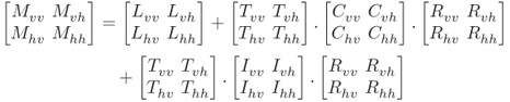
The S-parameter matrix of the reader, M, can be related to the S-matrix of other blocks by
In this equation, TDR shows the amount of coupling or direct leakage between transmit and receive antennas. This part is independent of the effect of the tag or other objects. Therefore, leakage, L, can be directly measured when there is nothing in front of the antennas.
Therefore, one can combine Equations (4.2) and (4.3) to have
As already assumed, the transmit signal is V-polarized and the receive signal is H-polarized. Therefore, ![]() is the interested S-parameter (forward transmission coefficient) for the proposed cross-polar system.
is the interested S-parameter (forward transmission coefficient) for the proposed cross-polar system. ![]() is also important to compare the performance of the proposed system with other copolar-based systems. These two S-parameters are driven by
is also important to compare the performance of the proposed system with other copolar-based systems. These two S-parameters are driven by


Equations (4.5) and (4.6) are related to the physical characteristics of the elements in the reading process. If they are carefully investigated, the complexity of Equations (4.5) and (4.6) can be reduced. For example, the terms Ivh and ![]() represent the depolarization aspect of the unwanted reflection toward the reader. The usual expectation is that reflection through surrounding objects would be at the same polarization. Specifically at millimeter-wave range, the objects are too big to create a depolarized signal due to the diffraction effect. Multipath interferences and clutter also show no depolarization behavior, hence
represent the depolarization aspect of the unwanted reflection toward the reader. The usual expectation is that reflection through surrounding objects would be at the same polarization. Specifically at millimeter-wave range, the objects are too big to create a depolarized signal due to the diffraction effect. Multipath interferences and clutter also show no depolarization behavior, hence ![]() and
and ![]() can be correctly assumed to be zero. Tij and Rij, on which
can be correctly assumed to be zero. Tij and Rij, on which ![]() , are related to the antenna polarization or the antenna's CPL. As shown in the following chapter, the designed array antenna for the proposed image-based chipless RFID system has a high CPL of more than 20 dB. Moreover, the PNA Agilent E8361A has a high-quality cable and connectors with very high isolation in the order of 80–100 dB [4]. This means that the value of
, are related to the antenna polarization or the antenna's CPL. As shown in the following chapter, the designed array antenna for the proposed image-based chipless RFID system has a high CPL of more than 20 dB. Moreover, the PNA Agilent E8361A has a high-quality cable and connectors with very high isolation in the order of 80–100 dB [4]. This means that the value of ![]() and
and ![]() are less than 0.01 and again can be correctly neglected.
are less than 0.01 and again can be correctly neglected.
By applying the aforementioned simplifications, Equations (4.5) and (4.6) become
In these formulas, ![]() refers to the leakage between Tx and Rx modules of the reader whether in co- or cross-polar directions. The following statements are related to the leakage:
refers to the leakage between Tx and Rx modules of the reader whether in co- or cross-polar directions. The following statements are related to the leakage:
- Leakage Measurement. In an empty environment, leakage (
 ) can be directly measured. The value of
  depends on the internal characteristics of the designed antenna and is also related to the physical distance between the Tx and Rx antennas. Once
  is measured, it does not change with varying the reading scene.
 - Significance of Leakage. The leakage for the copolar case would be much higher than that of the cross-polar scenario
 >
>  . If the copolar leakage (
 ) is not controlled well, it may significantly affect the final system performance.
 - Leakage Control. The leakage control in the copolar scenario,
 , is much more complex than that for the cross-polar,
  . This is because in the copolar case, both transmit and receive antennas are on the same polarization scheme and, hence, they are more likely to interfere with each other.
Therefore, it can be concluded that the leakage in the cross-polar case is much less than that of the copolar and, hence, it has less effect on the reading process. Moreover, the leakage control is also much easier in the cross-polar scenario. This is one of the most significant advantages of the cross-polar scenario over the copolar working basis.
In Equation (4.8), which relates to the cross-polar scenario, the term ![]() refers to the mixed effects of the Tx, Rx, and the tag. To accurately determine the coupling coefficient
refers to the mixed effects of the Tx, Rx, and the tag. To accurately determine the coupling coefficient ![]() due to the filtering effect of the transmitter and receiver antennas, it is required to utilize a reference tag with known scattering behavior. Therefore, the tag's scattering term (
due to the filtering effect of the transmitter and receiver antennas, it is required to utilize a reference tag with known scattering behavior. Therefore, the tag's scattering term (![]() ) can be easily found as
) can be easily found as

where ![]() is a fixed value based on the Tx and Rx antennas' distance and
is a fixed value based on the Tx and Rx antennas' distance and ![]() is the measured scattering parameter of the reference tag.
is the measured scattering parameter of the reference tag.
One may suggest performing the same approach for the copolar scenario. However, as it is clear from Equation (4.7), an extra term ![]() also exists for the copolar case. The
also exists for the copolar case. The ![]() counts the effect of reflections from surrounding objects around the tag. As the tag size is very small compared to other surrounding objects, the
counts the effect of reflections from surrounding objects around the tag. As the tag size is very small compared to other surrounding objects, the ![]() is much larger than the
is much larger than the ![]() in Equation (4.7). This means that it is not possible to extract the tag response without the information about its surrounding objects. Indeed, it is required to first calibrate the system based on a specific orientation of objects in the reading zone and then detect the response of the tag by subtracting two measurement results. Although with this calibration process, the tag reading would be possible in the copolar scenario, the approach is very sensitive to any changes in the surrounding objects' orientations or tag movement. This means that if the tag moves in the reading zone or if one object around the tag changes its place or aspect angle, then it is required to calibrate the system again. On the contrary, the cross-polar scenario is not dependent on the surrounding objects and no information is required. This is a very significant aspect of the cross-polar working basis, as the system is working well in an unknown reading zone only with a unique calibration setup. This aspect of the proposed cross-polar system is shown in a practical scenario in the following sections.
in Equation (4.7). This means that it is not possible to extract the tag response without the information about its surrounding objects. Indeed, it is required to first calibrate the system based on a specific orientation of objects in the reading zone and then detect the response of the tag by subtracting two measurement results. Although with this calibration process, the tag reading would be possible in the copolar scenario, the approach is very sensitive to any changes in the surrounding objects' orientations or tag movement. This means that if the tag moves in the reading zone or if one object around the tag changes its place or aspect angle, then it is required to calibrate the system again. On the contrary, the cross-polar scenario is not dependent on the surrounding objects and no information is required. This is a very significant aspect of the cross-polar working basis, as the system is working well in an unknown reading zone only with a unique calibration setup. This aspect of the proposed cross-polar system is shown in a practical scenario in the following sections.
4.3.2 Multipath Interference and Clutter
Interferences due to the reflections from objects around the tag are a major problem in many conventional chipless or even chip-based RFID systems. The analytical model of the system's performance regarding the multipath interference and clutter was shown for the co- and cross-polar systems. Here, the system is tested in a real environment to validate the mathematical expectation. The measurement setup is similar to that shown in Figure 4.1. The reading distance, transmit output power, and all other parameters are the same for comparison purpose. Exploring the effect of multipath and reflection interferences on the reading process, the measurement is accomplished in the lab environment and not in an anechoic chamber. Moreover, a harsh and severe multipath situation is implemented by using some randomly selected highly reflective objects. Three horn antennas are directed toward the reader antennas. A large printed circuit board with 35 × 45 cm2 is also placed in front of the reader just after the reading pole as shown in Figure 4.5.

Figure 4.5 (a) Severe multipath interference scenario and (b) high clutter for the reading process.
To simulate the high-clutter situation, a big metal plate is attached to the reading pole. The size of the plate is very large, 20 × 25 cm2, compared with the reader antennas and the reading distance (Figure 4.5). This highly reflective barrier causes a challenging situation for many traditional chipless RFID systems. The reflection from this plate (Iw) is much higher than that of the tag (Cvv) as discussed in the previous section. Therefore, the detection of the tag would be impossible unless the effect of high reflection is deleted through a calibration process. The calibration, however, is sensitive to any changes in the orientation of the objects around the tag and the tag movement.
The result of measurement for these two scenarios is shown in Figure 4.6. For comparison purposes, two results from normal measurement process, a “no tag” case and printed polarizers, are also repeated in Figure 4.6. As the graphs show, the effect of multipath interference and clutter on the received signal are almost negligible and very similar to the case when no tag is attached to the pole. This clearly matches with the analytical conclusion regarding the robustness of the cross-polar system to multipath and clutter interferences. Reflections from objects around the tag are mostly copolar, while the receiver picks up cross-polar components only. This significant advantage of the proposed cross-polar-based technique is very important in practice with respect to other copolarized-based systems [5–7]. In most cases, chipless RFID systems are vulnerable to multipath interferences and they require supplementary approaches, for example, multistep calibration or reference tags [6–9].

Figure 4.6 Measurement result for multipath and high-clutter situations.
4.4 EFFECT OF HIGHLY REFLECTIVE ITEMS
In the previous section, the robustness of the proposed technique toward severe multipath interferences and high-clutter situations has been verified. This section aims at evaluating the performance of the printed polarizers when they are attached to highly reflective items. This covers the ultimate practical scenarios of the chipless RFID systems. For this purpose, two highly reflective objects are considered. First, a plastic bottle containing water is measured. As the reflection from water is unpredictable, so it may cause degradation of the reading process. Second, an aluminum can containing liquid is considered. The high reflection from the conductive body of the container as well as the bending effect affects the measured results.
4.4.1 Liquid Container
A normal plastic bottle of water is considered for the measurement. The tag is a single-layer structure consisting of printed polarizers on paper. The object and attached printed tag are shown in Figure 4.7. The tag consists of normal printed meander lines as highlighted in the picture. The measurement result is also shown in Figure 4.7. For comparison purposes, the measured results of the “no tag” case are also shown in Figure 4.7. As the graphs show, when no tag is placed in front of the antennas, the received signal level is below −65 dBm. Having a water bottle with no attached tag that is relatively very large has a minor effect on the cross-polar component. A maximum of 5 dB increase is experienced in this case. However, if the same water bottle includes a tiny printed tag as shown in Figure 4.7, then the received signal is significantly elevated. The received signal level from the attached tag is 12 dB higher compared to when the water bottle has no attached tag. This margin provides a reliable reading scenario of the liquid containers. Therefore, it can be concluded that the system has satisfactory performance when attaching to the liquid container. It is important to mention that no calibration process has been used in obtaining the graphs of Figure 4.7. Obviously, with a calibration process, much higher signal level differences are expected.

Figure 4.7 (a) Printed meander line tags attached to a plastic bottle of water and (b) measurement result.
4.4.2 Metallic Objects
Tagging of metallic objects is always a challenging issue for RFID technologies due to the high reflection effect. An aluminum can is considered to evaluate system performance for this scenario. The tag is an etched-out meander line of conductive surface on paper. This means that the base of the tag is conductive and the meander line shape is paper. Therefore, this tag is a negative image of the former tag used in the previous step for the water bottle. The measurement setup and results are shown in Figure 4.8 with the highlighted tag structure. The received signal level for the “no tag” case is also depicted in this figure.

Figure 4.8 An etched-out printed meander line tag attached to an aluminum can and (b) measurement result.
An aluminum can containing liquid without any attached tag, if placed in front of the reading pole, increases 5–7 dB of the receive signal in the cross-polar direction. If the same object is accompanied by a tiny printed tag, then it creates at least 13 dB higher cross-RCS on the reader side compared with the “can only” case. It is again important to indicate that all the graphs in Figure 4.8 are the pure measured signal level without any calibration or cancelling out of interferences process. This measurement result clearly shows the potential of the proposed technique for tagging of metallic objects.
4.5 SECURE IDENTIFICATION
One of the limitations of the barcodes is the requirement for direct code reading, for example, barcodes shall be exposed to the items and it is not possible to hide optical labels inside the objects. On the other hand, however, chipped RFID systems normally provide the possibility of hiding the tags inside the items, hence suggesting secure identification. It is therefore an utmost benefit to verify the possibility of secure identification in the suggested spatial-based technique. This means that the polarizer-based tag is readable in no “line-of-sight” (LoS) condition. Before exploring this aspect of the system, it is important to clarify the LoS terminology in EM theory. The LoS normally refers to propagation of EM wave including optics in a straight line. Based on the frequency of operation, a radiocommunication link may be referred to as LoS or NLoS. Low-frequency EM wave does not need an LoS condition, HF broadcasting, for example. For higher bands, the transmitter shall see the receiver to be able to communicate effectively or an LoS condition is required, point-to-point communication in gigahertz bands, for example. Based on this assumption, the proposed technique of imaging system is obviously an LoS system. Therefore, a straight path between the reader and tag is required for data encoding purpose.
However, the LoS systems may be categorized further. The communication link in some LoS systems may require a clear/visible LoS between Tx and Rx without any obstacles. Very-high-frequency EM wave and specifically optical communication systems fall into this category. These systems may be referred to as optical LoS systems. However, there are LoS systems that operate effectively even if some obstructions, in the form of EM-wave transparent materials, are in the reading zone. To categorize these two systems, the word optical LoS is used for the first systems. The second type of systems may be referred to EM-LoS system. The optical-based identification systems, barcodes and QR codes, are definitely optical LoS systems. Any barrier, even dirt, may result in reading failure. This restricts the system flexibility and is seen as a main issue for many applications.
Considering the mm-wave band of operation, it is important to evaluate the system performance when the tag is read in None-optical LoS condition, tag in an envelope or inside a box as example. This shows the system performance in None optical LoS conditions. For this purpose, multiple barriers are placed between the tag and reader. In this process, the tag is covered by the medium. This is similar to the cases when the tag is attached to an item and covered by a medium as shown in Figure 4.9. The medium could be an envelope paper or a box made up from cardboard or plywood. Table 4.1 shows different types of media, their thickness, and material compositions. This selection may cover a wide range of items.

Figure 4.9 (a) NLoS reading scenario and (b) measurement process.
Table 4.1 Multiple Barrier
| Barrier Name | Thickness (mm) | Material |
| Bubble envelope | 4 | Paper and plastic |
| Foam | 18 | Polypropylene/polyethylene (EPP/EPE) |
| Cardboard | 2 | Torn cardboard |
| Plywood | 3 | Wood veneer |
| Wood | 20 | Wood |
The measured result and the images of different types of media are shown in Figure 4.10. For all cases, except for a tick wood (2 cm thickness), the system is adequately capable of detecting the presence or absence of the tag from the different measured signal levels in the cross-polar RCS of the tag. The millimeter-wave signals are very lossy in those media (plywood, cardboard, etc.) and mainly require a clear line-of-sight reading condition. However, as the system is cross-polar basis, the receiver is capable of detecting even a weak signal due to the natural cancelation of background noise. This provides a substantial advantage for the reading process. This simply means that in practical scenarios, the tagged objects can be packaged without affecting the data decoding process. It is important to emphasize that the results in Figure 4.10 are without any calibration process. Obviously, if the environmental effects are cancelled out with a predefined calibration process, then much cleaner signal level differences between the two cases are observed. This process may ease reading of the tag through 2-cm-thick wood as well.

Figure 4.10 Measurement results for NLoS scenarios with pictures of some barriers.
4.6 BENDING EFFECT ON TAG PERFORMANCE
In real identification and tracking applications, the attached tags, whether barcodes or RFID types, are vulnerable to bending effect. This means that when a tag is attached to an item, the tag may not necessarily be in a flat configuration depending on the shape of the item. This issue affects the performance of the tag in the decoding process. As the tag size increases, degradation of the system performance due to the bending effect is becoming a serious issue. There are very limited published works on the bending factors for RFID tags or even barcodes [10]. The proposed tag in the spatial-based technique is physically a miniaturized item because of its millimeter-wave frequency band. Consequently, the expectation is that bending would not be a serious issue for a wide range of products to which the proposed tag can be attached.
Therefore, the system may provide a good robustness toward bending due to its miniaturized nature. However, it is important to explore how tag bending may affect the reading process in a real scenario if the items are very small compared to the tag size.
Moreover, it is important to clarify the meaning of bending. The final tag structure is a narrow strip with a fixed width around 1–1.5 cm and the tag length varying from 5 to 10 cm depending on the demanded data capacity (Figure 4.11). Consequently, bending is expected to occur along the tag length and not on its width as highlighted in Figure 4.11.

Figure 4.11 Expected bending on tag length.
To verify the performance of the proposed tag with respect to bending, small paper rolls of varying radii are prepared to which a tag can be attached. These paper tubes are denoted as S-i; i = 1, 2, 3, 4. Figure 4.12 shows the tubes along with their radius. For comparison purposes, a pencil is also included in Figure 4.12. To better categorize the paper tubes, their radii along with the radii of some commonly used objects, such as a water bottle, an aluminum can, and a pencil, are summarized in Table 4.2. The second column of the table shows the curved radius of the objects to which the tag is attached. As can be seen, the radius of the biggest paper roll is smaller than that for a water bottle. The arc angle of the tag relates to the radius of the object to which the tag is attached. This arc angle also appears in Table 4.2. Figure 4.13 figuratively shows how the object radius is related to the arc angle of the attached tag. As the length of the attached tag is fixed, the bigger objects create less arc angle of the attached tag.

Figure 4.12 Different paper tubes with varying radii.
Table 4.2 Dimensions of Paper Tubes and Some Well-Known Items
| Attached Items | Curved Radius, R (cm) | Arc Angle (°) |
| Paper tubes S-1 | 2.5 | 34 |
| Paper tubes S-2 | 1.25 | 68 |
| Paper tubes S-3 | 0.85 | 101 |
| Paper tubes S-4 | 0.35 | 245 |
| Aluminum can | 3.25 | 26 |
| Water bottle | 2.75 | 31 |
| Pencil | 0.4 | 214 |

Figure 4.13 Relation between arc angle of attached tag and radius of objects.
Figure 4.14 shows the measurement setup for the bending effect purpose. Again two separate antennas are utilized as Tx and Rx that are located at 10 cm distance to the reading pole and antennas are connected to the PNA. The measured cross-polar components of the backscattered signal from various curvatures are depicted in Figure 4.15. For objects bigger than S-1(R = 2.5 cm), bending has negligible effect on the received power level. Examples include a water bottle and aluminum can. This clearly confirms system robustness for a wide variety of objects. This simply means that any object bigger than a water bottle experiences no bending effect on the proposed technique. For objects whose radii are R < 2.5 cm, the received power level gradually decreases. However, the receiver is still able to separate the signal of a bent tag from a “no tag” case. Only for items smaller than S-4 (0.35 cm radius), such as a pencil, bending significantly degrades the system performance. For those items, the received signal level is only 5 dBm higher than that of the “no tag” case, which may create uncertainty in the reading process. From a result, it can be concluded that items with a curvature radius of more than 1.25 cm have an acceptable performance when the tag is attached in the proposed technique.

Figure 4.14 System structure for bending effect measurement.

Figure 4.15 Measurement result based on different tag bending scenarios.
4.7 CONCLUSION
In this chapter, the suggested structure for the EM polarizers was processed based on different approachs to PCB and printing technique. The final tags in each approach were measured in real scenarios. While the precisely fabricated tags show almost similar response as predicted by simulation, the printed tag structure totally lost the resonance behavior. Irrespective of nonresonant response, the printed tags were still able to create significant cross-polar response in the backscattered signal, hence act appropriately as polarizer.
Then an analytical model of the reading scenario was developed based on radar theory. In the proposed equivalent network of the system, the effects of Tx and Rx antennas as well as the connecting cables and connectors were considered. Then the tag was considered in the communication channel between Tx and Rx antennas. Multipath and reflection from objects around the tag were also addressed in the analytical model. The system was mathematically analyzed and it was shown that the system is very robust to multipath interferences.
Moreover, it was shown that copolar-based systems are very vulnerable to changes in the reading zone and they require frequent system calibration. In contrast, the proposed cross-polar system only involves one single calibration process and the tag movement or other changes in the reading environment do not affect system performance. This issue was nominated as a significant advantage of the proposed technique compared to other current approaches in RFID applications, which are normally copolar based.
Different measurement scenarios were considered for confirmation of the analytical model of the system. First, a severe multipath situation and highly cluttered condition were considered and the tag response confirmed the system robustness as predicted by the analytical model. Then a printed meander-line-based tag was attached to a bottle of water. Moreover, an etched-out printed meander-line-based tag was considered as the negative image of the normal tag for attaching to an aluminum can. In both cases, the tag-reading process was successfully accomplished. While the effects of the water bottle and aluminum can without any attached tag were almost negligible in the cross-polar direction, the presence or absence of an attached printed tag could be easily detected by the reader system in a real scenario. This step confirmed a noticeable potential of the proposed theory with respect to other techniques in the RFID applications. Most proposed approaches in a chipless RFID system normally face difficulty in reading the tag in the presence of highly reflective items.
Next, the system was tested for NLOS conditions. Different types of barriers were placed between the tag and reader and then the system performance was measured. It was shown that the reader easily detects the presence or absence of printed polarizers for a wide range of barriers including, plywood, cardboard, and paper. This suggests huge potential for the proposed system on reading the tagged objects with an envelope or inside the box without the requirement for opening them.
In the last part of this chapter, the effect of tag bending is considered. The proposed tag structure showed a very good performance for a bent tag. This was initiated by the millimeter-wave band of operation, which resulted in miniaturized tag size with very low bending vulnerability. Only for objects that are very small and narrow, a pencil, for example, the bending may affect the reading process in the proposed chipless system.
The very successful performance of the proposed meander line as an effective EM-polarizer in harsh environments suggests a very robust system. Considering that all the measurements were accomplished in a real laboratory environment using a poorly printed tag, it appears that the proposed system for chipless RFID systems is fully practical for industrial applications.
REFERENCES
- 1. M. Skolnic, Radar Handbook, Third ed. McGraw-Hill, 2008.
- 2. W. Wiesbeck and D. Kahny, “Single Reference, Three Target Calibration and Error Correction for Monostatic Plarimetric Free Space Measurements,” Proceedings of the IEEE, vol. 79, pp. 1551-1558, 1991.
- 3. A. Vena, E. Perret, and S. Tedjni, “A Depolarizing Chipless RFID Tag for Robust Detection and Its FCC Compliant UWB Reading System,” IEEE Transactions on Microwave Theory and Technique, vol. 61, pp. 2982-2995, 2013.
- 4. Agilent Technologies. (Oct 2014). Vector Network Analyser. Available: http://www.agilent.com.
- 5. I. Jalaly and I.D. Robertson, “RF barcodes using multiple frequency bands,” in International Microwave Symposium Digest, IEEE MTT-S 2005.
- 6. C.M. Nijas, R. Dinesh, U. Deepak, A. Rasheed, S. Mridula, K. Vasudevan, et al., “Chipless RFID Tag Using Multiple Microstrip Open Stub Resonators,” IEEE Transactions on Antenna and Propagation, vol. 60, pp. 4429-4432, 2012.
- 7. Y.F. Weng, S.W. Cheung, T.I. Yuk, and L. Liu, “Design of Chipless UWB RFID System Using A CPW Multi-Resonator,” IEEE Antenna and Propagation Magazine, vol. 55, pp. 13–31, 2013.
- 8. F. Costa, S. Genovesi, and A. Monorchio, “A Chipless RFID Based on Multiresonant High-Impedance Surfaces,” IEEE Transactions on Microwave Theory and Techniques, vol. 61, 2013.
- 9. N. C. Karmakar, Handbook of Smart Antennas for RFID Systems. John Wiley, Singapore, 2010.
- 10. J. Siden, P. Jonsson, T. Olsson, and G. Wang, “Performance degradation of RFID system due to the distortion in RFID tag antenna,” in Microwave and Telecommunication Technology, Sevastopol, Ukraine, 2001, pp. 371–373.