
Chapter 17
2D–3D Conversion
17.1. Introduction
Native stereoscopic filming may be considered too costly in terms of time or resources. At times, filming may already have taken place, and the scene may no longer exist. In other cases, a posteriori 3D conversion is the only way of producing 3D content. The recent release of 3D versions of “older” blockbusters, such as Titanic, Top Gun or The Lion King, has made use of this technique. The conversion of “flat” 2D content into 3D content involves creating missing information. The process involves an automatic aspect, where parallax is created from other depth cues present in the scene, and an aspect carried out by human operators, adding a creative dimension to the procedure.
Methods developed for 2D–3D conversion may also be used for parallax correction in existing, but unsatisfactory, stereoscopic content. The 2D–3D conversion industry is currently expanding, with an estimated annual turnover of billions of dollars. Companies, such as Prime Focus, employ 1,200 workers in India for the conversion process alone. A number of directors have chosen to use this technique, including George Lucas for the Star Wars films and James Cameron for Titanic.
Although it presents certain advantages, 2D–3D conversion is not a simple process; situated on the border between technology and art, it requires continuous human intervention. The cost of high-quality conversion currently ranges from $50,000 to $150,000 per minute. Pioneers in the domain include In-Three Inc., Legend3D, Sony Pictures Imageworks and Passmore Lab.
2D–3D conversion is carried out almost exclusively using a depth map. Various methods of calculating a depth map from a stereoscopic pair have been put forward, including work by Lucas and Kanade [LUC 81], Horn and Schunck [HOR 81], Periaswamy and Farid [PER 03], Wu et al. [WU 00], Alvarez et al. [ALV 00], Schmidt [SCH 02] and Ran and Sochen [RAN 00]. While the domain has been explored in detail, the generation of a depth map from a single image is a problem, which presents an infinite number of solutions, and the proposed methods cannot, therefore, claim to offer universally acceptable solutions.
17.2. The 2D–3D conversion workflow
2D–3D conversion involves creating the second image of a stereoscopic pair from the first image. The process may be divided into four stages [MIC 11]:
17.3. Preparing content for conversion
17.3.1. Depth script
Before converting a whole film or a series of sequences for insertion into an existing production, a depth script is created, where sequences with depth effects are clearly identified, alongside maximum values for the depth budget that will be applied to the sequences for conversion. Note that decisions made at this level are essentially artistic, but they must also take account of technical limits imposed on the production, such as the maximum positive parallax, which depends on the size of the screen used for projection. This depth grading procedure must also impose values for each sequence, or each character or object present in a sequence, which will remain comfortable for the spectator [SEI 12]. Thus, positive parallaxes will be lower in productions for a juvenile audience, as children have a smaller interocular distance than adults [DOD 04]. Decisions affecting the depth budget also take into account the temporal succession of sequences in order to avoid sudden changes in the distance of the zone of interest during scene changes.
17.3.2. The advantage of video over fixed images
Image sequences are clearly more practical than separate fixed images when carrying out conversion. In a video or cinema sequence, a considerable amount of redundancies exist between consecutive images, providing an important information source for the artifact removal stage described above. This is particularly true in cases where the camera is subject to lateral horizontal movement during the sequence. From a conversion perspective, the most useful sequences are those which contain a predictable horizontal motion parallax; the most typical cases of this type include a camera mounted onto a traveling chariot, moving perpendicular to the view axis. A number of other cases offer usable motion parallaxes, such as objects, vehicles or characters, in relative movement with each other or with the background. The usefulness of these movements is increased by regularity; they include translations (vehicles on a road) and rotations (fairground rides, fan blades). Motion parallaxes are easier to use for objects with clear borders, which are easy to segment precisely, such as vehicles, buildings or manufactured objects.
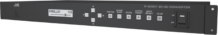
Figure 17.1. The professional JVC IF-2D3D1 package performs automatic 2D–3D conversion in addition to other stereoscopic processes
17.3.3. The automatic conversion trap
2D–3D conversion combines complex algorithms with knowledge and abilities of experienced human operators. To date, no 100% automatic procedure has been able to provide wholly satisfactory results in all cases.
A certain number of professional 2D–3D converters are available on the market, but none of these converters can guarantee perfect results for video sequences of unknown origin. However, some converters offer acceptable results in highly constrained environments, such as a football stadium with fixed cameras, controlled lighting and a scene geometry containing few different depth planes. The use of this type of equipment for live broadcast, however, remains risky.
Certain specific error types are generally encountered with 2D–3D converters. Objects in the foreground of an image may appear in the background and vice versa. Transparency, and fine structures, which are difficult to segment, such as rain, hair or the holes in a tennis racket, are generally badly interpreted or completely ignored by converters. The segmentation process may consider fine structures as noise and integrate them into the background, or over-segment them, integrating parts of the background. In both the cases, the results are unconvincing in terms of depths.
A variety of simple and inefficient converters are available to the public, both as software [GMB 10] and specific devices [IPP 11]. The simplest of these methods consists of taking the stereoscopic pair of the following image or the previous image of a video sequence as the second image. If the camera captures a regular panoramic lateral view, the disparity between two consecutive images produces a 3D effect; the faster the camera moves, the stronger the effect is. This approach rarely works and, if the camera moves in a vertical plane, the results are very uncomfortable. Moreover, if the camera changes direction, the depth effect is inverted and the background switches to the foreground. A more sophisticated variation of this method only conserves the horizontal image shift component, reducing undesirable effects, but this does not prevent the 3D effect from disappearing when the camera ceases to move.
17.3.4. Specific cases of automatic conversion
A simple mechanism whereby a left image is created using the previous right image in chronological order can produce good results. This is the case for lateral views taken from an airplane in constant linear flight, a method used from before World War II in aerial reconnaissance. A number of refinements have been used to improve the effectiveness of this technique [KNO 07, MAT 97, MOU 05].
In the case of sequences containing considerable nonlinear movement, certain methods can produce acceptable results. These methods, based on the use of motion vectors used in MPEG compression of video streams for television, give variable, and sometimes satisfactory, results; one example of this type was developed by Ideses et al. [IDE 07].
Static capture in closed environments produces favorable conditions for real-time automatic conversion. This is the case for a majority of sporting events [GRA 10, SCH 11]. These real-time conversion techniques use a priori knowledge of the scene, including distances or reference points. After an initial automatic camera calibration phase, these algorithms generally calculate a background model in the form of an image mosaic. This background is made up of all of the static elements in a scene. The following step consists of creating a depth map, which will not (or barely) change over time and may even be reused as long as the location remains unchanged. The calculation of this depth map generally requires additional information, such as the length of pitch lines or the position of certain points. Dynamic foregrounds are obtained by differences with the background model. Different procedures are used to associate depth with these foreground images; the simplest method is to associate each silhouette with the depth of the ground element at its base.
17.3.5. Optimal content for 2D–3D conversion
In many cases, sequences or even whole movies are filmed in 2D, and then converted to 3D in postproduction. This reduces filming costs, although the conversion phase greatly increases the total cost of the film. In these cases, framing and scene setting are carried out as if 3D filming was used, avoiding foregrounds that cut across frame edges and depth jumps in scene changes and prioritizing long shots.
We should note, however, that even semi-automatic conversion can be extremely labor-intensive for certain types of scenes. The complexity and, a fortiori, the cost of conversion increases according to the number of depth layers used in a scene. If one of the essential elements in the scene has a highly complex geometric structure, such as a plant or a crowd of people, a stereoscopic camera will always give better depth rendering. Scenes filmed using a crane or steadicam may also be difficult to convert due to the presence of irregular and nonlinear movements.
In the same way, transparency and atmospheric phenomena, such as rain, snow or fog, further complicate the conversion process. First, the segmentation between the foreground and background ceases to be clearly defined: a single pixel may be part of several planes at once. This complicates the creation of the depth map and the generation of the stereoscopic image pair. Secondly, this type of effect can drastically increase the number of depth layers used in a scene.
In other cases, 2D–3D conversion may be highly efficient [DEJ 08]. In the case of concerts or other scenes using significant lighting effects, 2D–3D conversion may be used to avoid asymmetry in light reflections between left and right images. Conversion is also used when the equipment used is poorly suited to 3D filming (tele-photo lenses which compress scenes, macro etc.). Nevertheless, certain rules should be followed to increase the chances of successful conversion:
When a movie is filmed with the intention of carrying out 3D conversion in post-production, efforts must clearly be made to simplify the conversion process. Thus, scenes including effects, made up of several shots or including CGI elements are pre-separated into superposed layers; for elements created using 3D modeling software, a depth map is provided automatically.
The Walt Disney Pictures movie G-Force is an example of partial conversion, carried out by In-Three, pioneers in 2D–3D in Hollywood, using a procedure called dimensionalization. In G-Force, scenes filmed in 2D were converted and then integrated into a synthesized, computer-generated world.
17.4. Conversion stages
The purpose of the industrial video conversion workflow is to create the second view of a stereoscopic pair using the first view. For reasons of efficiency, the various stages in the procedure are carried out by dedicated workers or programs. As automatic algorithms are unable to produce perfect results for each stage, visual checks by experienced staff are necessary after each of the stages mentioned below:
All of these stages, with the exception of step 6 which is completely automatic, are semi-automatic, meaning that they use algorithms and computing tools manipulated by human users. One example of this is the automatic detection of contours, which are then corrected using spline/bezier tools.
17.4.1. The segmentation stage
The detection of key images is a manual operation which does not involve a complex algorithm. Segmentation, the crucial first stage in the workflow, is different. Each key image is split into main elements which are non-contiguous in terms of depth: sky, ground, objects and characters. The segmentation of an image into distinct elements is easier in a video sequence than in a single fixed image, as the movement of objects in relation to one another generates a movement parallax, allowing contour determination. The segmentation program also determines the relative distance between objects: the character is in front of the table, which is in front of the sky, etc. We thus establish a classification of values between the various elements of the final depth map. A variety of segmentation methods may be used based on different visual criteria such as color, shape and other characteristics of objects and characters [AHA 06, CHE 98, FRE 97, GOR 97, KIN 01, MAL 93, VIO 04]. It is easy for the human eye to follow the silhouette of a moving object in a video sequence. The most promising automatic segmentation methods are based on optical flows.
Optical flow methods calculate the trajectory of each pixel in an image according to its movement history, and thus determine where and when an element appears and disappears and when it is hidden by another object. Precise optical flow calculation, applied to all pixels of an image, was long considered to be impossible due to its considerable requirements in terms of processing power. The development of massively parallel graphics processing units (GPUs) has changed this, and calculations of this type may now be carried out in real time. By knowing the precise trajectory of each pixel, we may interpolate their positions and thus detect the contours of moving objects in front of a static or slow-moving background.
Segmentation is not easy: in many cases, the edges of objects or characters are not clear. Partially transparent elements, such as hair blown by the wind, lace veils, clouds of smoke or the strings of a tennis racket are difficult to separate from their background.
17.4.2. Depth maps: calculation and propagation
Once the relative distances between the elements of the scene have been obtained, each element is assigned an absolute distance in relation to the camera. This stage may, clearly, be carried out manually, but an intelligent program can prove effective and make use of a number of depth cues used by the human brain: a priori knowledge of objects, the relative size of several identical objects, etc. A human head in closeup, for example, will clearly be close; a human silhouette of one-fourth of the height of the screen will be approximately 10 m away, a car of a few pixels in length will be in the background, and the sky will be considered to be in the background.
An automatic algorithm begins by seeking a horizon as exterior shots are often used. It then applies a first estimation: the sky is in the background, and the ground approaches in a linear manner from the horizon to the foot of the camera. All possible depth cues are explored and used, whether automatically or manually:
Figure 17.2. a) Starting image of a depth map conversion; b) depth map with two segmented elements; c) the same depth map after depth matching between two points at the same distance from the two elements

At this stage, we obtain a depth map made up of several planes that can be recognized by their different brightnesses. Each element in the image then needs to be refined; these elements are generally memorized in several distinct superposed layers, and the depth of each is determined by imposing a light level variation in the depth map, giving an inclination or roundness. Once again, monocular depth cues are used to add details to the result, such as shadow and light effects showing the shape of a face. A priori knowledge of objects and characters is also very important. This knowledge is used, for example, to round out faces or balls by directly modifying the depth map by hand or by creating computer models of these elements from which the depth map may be extracted. This operation is generally supervised and corrected by hand. Thus, the operator ensures that characters are correctly anchored to the ground by giving their feet the same depth (and thus the same shade in the depth map) as the ground below them. At the end of this stage, the key image has a perfect depth map, and a first result may be visualized on screen before proceeding to the next step.
Next, using these depth maps of key images of a video sequence, interpolation techniques are applied to create depth maps corresponding to intermediate images. Simple linear interpolation may be used if the movement is sufficiently uniform. In all cases, the aim is for the depth values between two key images to follow movement, while remaining coherent in relation to the depth specified in the key images. The quality of segmentation and of movement estimation is crucial in ensuring successful interpolation. Temporal filtering of depth maps may also be used to improve quality, increasing the coherence of depth across a whole sequence [BLE 09]. Manual validation is always helpful, as a movement that initially appears linear may not, in fact, be completely linear; segmentation contours, depth values and other parameters may then need to be adjusted.
17.4.3. Missing image generation
All of the original images are now associated with a depth map. At this stage, each pixel of the original image needs to be shifted horizontally over a distance proportional to its depth. In professional workflows, the values of Z are usually coded in the form of 16-bit integers. The horizontal shifts needed for depth rendering are generally less than 3% of the width of the image and are strongly nonlinear as a function of depth. Thus, a horizontal shift of one pixel may correspond to several tens of meters, and shifts of a fraction of a pixel are required for correct rendering.
Each sequence of a film must follow a fixed depth budget, using the minimum and maximum authorized parallax values for the shot. This budget is determined by a stereographer as a function of the size of the screen used for image projection and of the desired depth amount from an artistic perspective. The stereographer also determines the value corresponding to the screen plane. The face of the main actor, for example, may be set at parallax zero. The shade of gray of this point in the depth map will thus be chosen as the reference point.
As the depth budget is often only a few pixels deep, or at most tens of pixels behind the screen plane, fractional shifts are often used. It is not rare to need to situate tens of objects or individuals at different distances using only a few pixels of parallax difference.
Once the values of gray from the depth map corresponding to minimum, zero and maximum parallax values have been fixed, an automatic procedure easily applies the desired shift transformation to each pixel of each image in a sequence. On-screen 3D verification of the whole sequence is then possible.
The horizontal shift of large parts of an image, which may be substantial, is not without its problems. When two neighboring pixels shift over different distances, two situations may arise: superposition, or a hole. In the first case, as the shifting program begins with the furthest pixels, the closer pixel is layered without creating an artifact: the closest objects always hide objects that are further away. In the second case, part of the image will contain no information, as the shift shows part of the scene that was not present in the original image; this creates a hole. Automatic methods use various heuristics, such as simple duplication of a neighboring pixel to fill the hole. Other heuristics synthesize the missing pixel by interpolating or extrapolating the color of neighboring pixels. The most intelligent algorithms search for the missing information in previous and subsequent images of the same sequence using heuristics such as those described above in case of failure. Once a section of an image has been constructed, the most important point is to avoid retinal rivalry: it is essential to check that the added pixel and its homologue in the original image do not present excessive luminosity or color differences.
Figure 17.3. Left: a depth map using the whole depth budget. Right: a depth map where the whole scene has been relegated behind the screen. The histogram of the depth map is shown under each image

Methods which create multi-layer depth maps simplify the problem as each layer may be corrected independently of the others. The result is never perfect, but visual examination (on a 3D display) allows the most significant errors to be detected. As a general rule, this stage is semi-automatic using algorithmic correction followed by visual checks and, where necessary, manual correction by an experienced operator.
17.5. 3D–3D conversion
Interestingly, the demand for 2D–3D conversion has led to the emergence of a number of algorithms and methods which may be used to regenerate stereoscopic pairs using existing, but unsatisfactory, stereoscopic content. Correction is often required in cases where there are errors in scene geometry (the foreground is too close) or in geometric calibration of camera settings (interaxial distance or convergence errors). As filming costs can be very high, notably for movies, 3D sequences may be recreated in post-production using depth maps calculated precisely using stereoscopic originals, using one of the methods described above.
In these cases, the depth budget used is different to that used in the original, and applied to one of the two original images following a process similar to that used in 2D–3D conversion. The advantage of two original images is exploited in the artifact correction phase, providing an additional source of background information. Legend3D are specialists in this 3D–3D conversion workflow, with its StereoWorks division created in 2012.
17.6. Conclusion
2D–3D conversion is on the border between technical and artistic activities, and human participation remains essential. A depth script is established for each sequence for conversion prior to execution of a variety of partly manual and partly automated stages. The 2D–3D conversion workflow is broken down into a series of stages, notably depth map generation, segmentation, missing image generation and artifact suppression.
Certain commercial solutions offer fully automated 2D–3D conversion, but the results are generally unsatisfactory, with the exception of very specific cases where the geometry of the scene is subject to strong constraints, movements are linear and predictable and segmentation is simple. Not all content is equally suited to 2D–3D conversion. Conversion is notably facilitated when planned during the filming phase. In these cases, the costs and complexity of filming are identical to those involved in 2D filming, and the conversion stage, with the benefits of favorable framing, staging and other conditions, does not have excessive effects on the production budget.
17.7. Bibliography
[AHA 06] AHARON M., ELAD M., BRUCKSTEIN A., “K-SVD: An algorithm for designing overcomplete dictionaries for sparse representation”, IEEE Transactions on Signal Processing, vol. 54, no. 11, pp. 4311–4322, November 2006.
[ALV 00] ALVAREZ L.J., DERICHE R.D., SÁNCHEZ J., et al., Dense disparity map estimation respecting image discontinuities: a PDE and scale-space based approach, Research report no. RR-3874, INRIA, 2000.
[BLE 09] BLEYER M., GELAUTZ M., “Temporally consistent disparity maps from uncalibrated stereo videos”, Proceedings of the 6th International Symposium on Image and Signal Processing and Analysis (ISPA), Salzburg, pp. 383–387, 16–18 September 2009.
[CHE 98] CHEN S., DONOHO D., SAUNDERS M., “Atomic decomposition by basis pursuit”, SIAM Journal on Scientific Computing, vol. 20, no. 1, pp. 33–61, 1998.
[DA 10] DA SILVA V., “Depth image based stereoscopic view rendering for MATLAB”, available at http://www.mathworks.com/matlabcentral/fileexchange/27538-depth-image-based-stereoscopic-view-rendering, 2010.
[DEJ 08] DEJOHN M., SEIGLE D., A summary of approaches to producing 3D content using multiple methods in a single project, Report, In-Three, 2008.
[DOD 04] DODGSON N.A., “Variation and extrema of human interpupillary distance”, Proceedings of SPIE, Stereoscopic Displays and Virtual Reality Systems XI, vol. 5291, San Jose, CA, pp. 36–46, May 2004.
[FRE 97] FREUND Y., SCHAPIRE R.E., “A decision-theoretic generalization of online learning and an application to boosting”, Journal of Computer and System Sciences, vol. 55, no. 1, pp. 119–139, 1997.
[GMB 10] GMBH E.M., “MakeMe3D software”, available at http://www.makeme3d.net/convert_2d_to_3d.php, 2010.
[GOR 97] GORODNITSKY I.F., RAO B.D., “Sparse signal reconstruction from limited data using FOCUSS: a re-weighted minimum norm algorithm”, IEEE Transactions on Signal Processing, vol. 45, no. 3, pp. 600–616, March 1997.
[GRA 10] GRAU O., VINAYAGAMOORTHY V., “Stereoscopic 3D sports content without stereo rigs”, SMPTE Motion Imaging Journal, vol. 119, pp. 51–55, 2010.
[GRA 12] GRAZIOSI D., TIAN D., VETRO A., “Depth map up-sampling based on edge layers”, Signal Information Processing Association Annual Summit and Conference (APSIPA ASC), Hollywood, CA, pp. 1–4, 3–6 December 2012.
[HOR 81] HORN B.P., SCHUNK B.G., “Determining optical flow”, Artificial Intelligence, vol. 17, pp. 185–203, 1981.
[IDE 07] IDESES I., YAROSLAVSKY L., FISHBAIN B., “Real-time 2D to 3D video conversion”, Journal of Real-Time Image Processing, vol. 2, pp. 3–9, 2007.
[IPP 11] IPP, “3D media converter box”, available at http://ippstore.com/3D_Media_Converter_Box.html, 2011.
[KIN 01] KINGSBURY N., “Complex wavelets for shift invariant analysis and filtering of signals”, Applied and Computational Harmonic Analysis, vol. 10, no. 3, pp. 234–253, 2001.
[KNO 07] KNORR S., SIKORA T., “An image-based rendering (IBR) approach for realistic stereo view synthesis of TV broadcast based on structure from motion”, IEEE International Conference on Image Processing, ICIP 2007, San Antonio, TX, vol. 6, pp. VI–572–VI–575, 16 September–19 October 2007.
[LUC 81] LUCAS B., KANADE T., “An iterative image registration technique with an application to stereo vision”, Proceedings of the International Joint Conference on Artificial Intelligence (IJCAI), Vancouver, Canada, pp. 674–679, April 1981.
[MAL 93] MALLAT S., ZHANG Z., “Matching pursuits with time-frequency dictionaries”, IEEE Transactions on Signal Processing, vol. 41, no. 12, pp. 3397–3415, December 1993.
[MAT 97] MATSUMOTO Y., TERASAKI H., SUGIMOTO K., et al., “Conversion system of monocular image sequence to stereo using motion parallax”, Proceedings of SPIE 3012, Stereoscopic Displays and Virtual Reality Systems IV, pp. 108–115, 15 May, 1997.
[MIC 11] MICHEL B., “La conversion 2D–3D”, in La Stéréoscopie Numérique, Eyrolles, Chapter 5, 2011.
[MOU 05] MOUSTAKAS K., TZOVARAS D., STRINTZIS M., “Stereoscopic video generation based on efficient layered structure and motion estimation from a monoscopic image sequence”, IEEE Transactions on Circuits and Systems for Video Technology, vol. 15, no. 8, pp. 1065–1073, August 2005.
[PER 03] PERIASWAMY S., FARID H., “Elastic registration in the presence of intensity variations”, IEEE Transactions on Medical Imaging, vol. 22, no. 7, pp. 865–874, July 2003.
[RAN 00] RAN A., SOCHEN N.A., “Differential geometry techniques in stereo vision”, 6th European Workshop on Computational Geometry, pp. 98–103, 13–15 March 2000.
[SCH 02] SCHMIDT J., NIEMANN H., VOGT S., “Dense disparity maps in real-time with an application to augmented reality”, Proceedings of the 6th IEEE Workshop on Applications of Computer Vision (WACV 2002), IEEE, Orlando, FL, pp. 225–230, December 2002.
[SCH 11] SCHNYDER L., WANG O., SMOLIC A., “2D to 3D conversion of sports content using panoramas.”, in MACQ B., SCHELKENS P. (eds), ICIP, IEEE, pp. 1961–1964, 2011.
[SEI 12] SEIGLE D., “Depth grading in 3D creation”, available at http://www.docstoc.com/docs/94241109/Depth-Grading-in-3D-Creation, 2012.
[VIO 04] VIOLA P., JONES M., “Robust real-time face detection”, International Journal of Computer Vision, vol. 57, no. 2, pp. 137–154, 2004.
[WU 00] WU Y.-T., KANADE T., LI C.-C., et al., “Image registration using waveletbased motion model”, International Journal of Computer Vision, vol. 38, no. 2, pp. 129–152, 2000.
[XU 11] XU F., LAM K.-M., DAI Q., “Video-object segmentation and 3D-trajectory estimation for monocular video sequences”, Image and Vision Computing Journal, vol. 29, no. 2–3, pp. 190–205, 2011.