Chapter 1
Foundation
1.1. Introduction
Audiovisual production has, for a number of decades, used an increasing number of ever more sophisticated technologies to play 3D and 4D real and virtual content in long takes. Grouped under the term “3D video”, these technologies (motion capture (Mocap), augmented reality (AR) and free viewpoint TV (FTV) and 3DTV) complement one another and are jointly incorporated into modern productions. It is now common practice to propose AR scenes in FTV or 3DTV, either virtual or real, whether this relates to actors, sets or extras, giving virtual characters (both actors and extras) realistic movements and expressions obtained by Mocap, and even credible behavior managed by artificial intelligence.
With the success of films such as The Matrix in 1999 and Avatar in 2009 (see Figure 1.1), the acronym “3D” has become a major marketing tool for large audiovisual producers. The first, The Matrix, popularized a multiview sensor system containing 120 still cameras and two video cameras allowing slow motion virtual traveling, an effect known today as bullet time. This system has since been subject to various improvements which today not only allow the reproduction of this type of effect (FTV), but also for complete or parts of 3D reconstructions of scene content. The success of Avatar marked the renaissance of 3D cinema, a prelude to 3DTV even if it is not yet possible to free viewers from wearing 3D glasses. Glasses-free, or “autostereoscopic”, 3D display is undeniably advantageous in comparison to glasses-oriented technology due to its convincing immersive 3D vision, non-invasiveness and only slightly higher production costs in relation to 2D screens. Unfortunately, the need of multiple viewpoints (generally between five and nine) to yield immersion involves a spatial mix of these multiple images which limits their individual resolution. As a result, in contrast to stereoscopy with glasses, autostereoscopic visualization is not yet available in full HD. The induced loss of detail in relation to this current standard further limits its use. The principle challenge of autostereoscopy currently concerns the conversion of the overall dedicated tool chain into full HD.
Figure 1.1. Multiview system used to film The Matrix©Warner Bros. Entertainment Inc. a): 120 still cameras and two video cameras enabling time slicing (bullet time effect); b): stereoscopic filming; c): omnidirectional 3D capture for Avatar©20th Century Fox by James Cameron

This profusion of technologies, a veritable 3D race, is probably the result of the rapid banalizing of effects presented to the public, despite the fact that the technologies used have not yet been fully perfected. This race therefore evidently raises further challenges. All these techniques have a point in common. They rely on multiview capture of real scenes and more or less complex processing of the resulting recorded media. They also raise a series of problems relating to the volume of data, at each stage of the media chain: capture, coding [ALA 07], storage and transmission [SMO 07], concluding with its display. It is therefore essential to be able to synthesize the characteristics of this data as systems which mark their use in order to consolidate the bases of this technological explosion.
It is this point, which is the central proposal of this book, which examines two interrelated fields of this technological domain, as summarized by Kubota et al. [KUB 07]:
– 3D video technologies which aim to reconstruct varying scene characteristics (geometry, lighting and movement) for various uses;
– 3DTV/FTV technologies which focus on displaying in 3D, sometimes interactively; 3D scenes with less precise reconstruction requirements but which raise more clearly the challenges of transmitting and coding 3D or multiview medias.
The aim of this chapter is to introduce the fundamental principles of 3D videos and the techniques involved in this. In the following section, we will examine an overview of the different periods of history which have marked the development and formalization of 3D. Notably, we will detail the geometric principles related to central projection (pinhole cameras) without extending these developments to stereovision, the principles of epipolar geometry [HAR 04] exposed in Chapters 3, 4 and 5. We will then examine aspects relating to the physiology of human vision before concluding, with a more taxonomic perspective, by proposing a classification of 3D visual approaches.
1.2. A short history
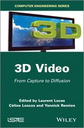
The term “3D images” is the name given to what was known as “perspective” during the Renaissance period. While new developments concerning 3D arose during this period, with the appearance of the first 3D drawing machine (see Figure 1.2), consciousness of this sensation, as was its corollary–3D perception is far more ancient and founded during Antiquity.
Figure 1.2. a): the Dürer perspectograph; b): the ideal city (1475) from Piero della Francesca, c): Brunelleschi experiment
In this section, we present a brief overview of different periods which saw the development and theorization of 3D and its extension to stereoscopy using binocular vision. These two aspects mentioned in the following sections are independent of one another for practical reasons, as they need to be examined from a more global perspective, defining our relation to imaging.
1.2.1. The pinhole model
The pinhole camera, or camera obscura, was the precursor to the modern- day camera. It is composed of a dark room with a narrow hole, from which its name is derived, by which exterior lit objects are projected, in reverse, onto the opposite internal side of the dark room.
This principle was first described by the Mohists, a pacifist Chinese sect, in a collective work [MOH 00] written around 400 B.C. under the pseudonym Mo Zi. Aristotle also referred to it in the 4th Century B.C. [ARI 36]. Its first mathematical formulation was proposed by the Persian mathematician Alhazen (Ibn Al-Haytham) [ALH 21], one of the founders of optics, notably for his descriptions of vision. In 1515, Leonardo da Vinci detailed the principle and noted that, to produce a clear image, the hole must not exceed 0.5 mm in diameter [VIN 19]. In 1556, his Italian friend Girolamo Cardano placed a convex glass lens in front of the hole which provided images with hitherto unseen clarity [CAR 56]. This added the photographic lens to his long list of scientific and technical contributions1.
1.2.1.1. A modern-day form of expression
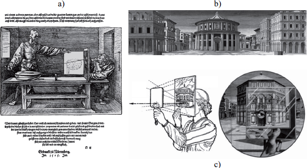
As a result, the pinhole camera is, first and foremost, a simple yet antiquated imaging device. Its principle of central projection on a plane is illustrated in Figure 1.3 that shows the object/image inversion resulting from the central downward-projection through the hole.
Figure 1.3. A pinhole camera (camera obscura): a): illustration from The Encyclopedia of Diderot & d’Alembert; b): geometric model of the central projection involved
The geometric optical model of this device is shown in Figure 1.3. The center of projection O is the hole, located at a distance of fc from the back of the darkroom to which the optical axis is orthogonal while passing through O. It is usual to define a “viewer” orthonormal reference frame (O, x, y, z), with z being orthogonal to the back plane of the darkroom and directed, like the implicit viewer, toward the outside of the room: x, for example, is “horizontal”, directed toward the right of the presumed viewer and ![]()
This model gives the relation ![]() which explains the observed inversion and characterizes the projection equation in (O, x, y, z) in Cartesian [1.1] as well as homogenous [1.2] coordinates:
which explains the observed inversion and characterizes the projection equation in (O, x, y, z) in Cartesian [1.1] as well as homogenous [1.2] coordinates:


1.2.1.2. From the pinhole to the camera
The pinhole camera, a relatively simple design, is occasionally used today despite several disadvantages that led to the common use of its successor, the modern-day still camera:
– The hole must be narrow to maintain a clear image. The image at the back of the room of a lit point at the depth z is generated uniquely by the beams emitted by this point and passing through the hole, forming a spot of light in the same shape as the hole dilated by a factor of 1 + fc/z.
– It cannot be too narrow to avoid too much diffraction at its edges as this may create blurring.
– The tiny surface area of the hole yields a weak illumination at the back of the room which requires a long exposure time and induces risk of motion blur.
To lessen these difficulties, according to Girolamo Cardano, the still camera replaces the hole with an objective composed of a lens or, more generally, an axial collection of lenses and a diaphragm, or iris, which controls the aperture of the admitted incidental conical beams. This camera lens improves the illumination at each point at the back of the room which facilitates the consensus between exposure time and depth of field. It solves the problems of diffraction that occur with pinhole cameras but has its own specific drawbacks:
– A depth of field controlled by the iris, yet more limited in a pinhole device because the solid angle of the conical incident and refracted beams is generally greater.
– Geometric aberrations (spherical, coma, etc.) related to thick lenses which cannot ensure perfectly precise convergence of the refraction of a conical incident beam generate a wider projection of this beam at the back of the room, even if it comes from the optimal distance.
– Chromatic aberrations related to variations in the refractive index for different wavelengths which disperse, as they exit the lens, the colored components initially carried together by incident rays.
– Radial distortions corresponding to an axial displacement of the actual optical center according to the main beam incident angle. As a result, convergences at the back of the darkroom exhibit radial barrel or pincushion deformations.
1.2.1.3. A standard digital camera model
These problems can be mitigated by using complex lenses (aspherical, achromatic, apochromatic, etc.) and/or digital post-processing of images with prior calibration. As a result, these improvements/corrections are generally presumed to be preprocessed when using images taken by a digital camera. This leads to the assumption that these images have been shot via central projection on a sensor placed on the back wall of the darkroom. This approximation, which ignores the impact of a non-pinhole shutter, is valid with regard to the acceptable depth of field of the digital images. It refers to the zone of depth within which a 3D point is projected at the back of the darkroom as an area smaller than the interpixel space (or pitch) of the sensor.
It should be stated that this model is somewhat of a throwback because it is exactly the model of the pinhole device, the forebear of the modern camera.
Some digital applications use non-central zones in the sensor. This is notably the case for multiview acquisition with decentered parallel geometry (see Chapter 4). Let us examine a simplified geometric model (pinhole shutter) of an ideal camera (whose residual flaws are corrected by post-processing), corresponding to a central projection through an optical center O on a decentered rectangular region of interest (ROI) in a 2D digital sensor, placed at the back wall of the darkroom. This model, which can be termed a “decentered pinhole” extends the pinhole model (centered) from which it differs only through its ability to decenter the sensor’s ROI. This book uses this characteristic and this more general model. More specifically, the sensor is placed (at the back wall of the darkroom) at a distance of fc from O, has a pitch of (ph, pv) and its ROI has a size of (nc, nl) which is potentially decentered by (cx, cy) pixels in relation to the optical axis (see the downward (bottom) part of Figure 1.4).
Figure 1.4. Decentered and normalized reverse pinhole: from above (according to the y-axis), the projective geometries of the real sensor and its normalized virtual representation

The inversion involved in these models, whether centered or not, between the axes of the image and that of the setting is generally countered by producing an upward rather than downward inverted projective model, known as a “reverse pinhole”. The placement of the “virtual sensor” (a reverse upward avatar of the sensor’s ROI) can therefore be optimized so that distances in pixels and “metric” distances can be confused, at least horizontally. It is sufficient to place the virtual projection plane, upwards, at a distance of f = fc.1/ph of O. This ensures a unitary horizontal pitch for the virtual sensor whose vertical pitch is therefore equal to the anamorphosis relation ρ = pv/ph of the real sensor. We refer to this as a “normalized reverse pinhole model”.
The “decentered and normalized reverse pinhole model”, a version decentered from its predecessor, is presented in Figure 1.4. The downward part (bottom) in the figure shows the direct decentered model of the ROI of the real sensor, while the upward part (top) presents the reverse model associated with the virtual sensor. Some specific data relating to the real sensor, its ROI and its virtual sensor includes the following:
– the sensor has a pitch of (ph, pv);
– its ROI has a size of (nc, nl) and is decentered by (cx, cy) pixels;
– its center is therefore situated at –(cx.ph, cy.pv, fc) in (O, x, y, z);
– a real cell (x, y) is situated at ![]()
– the virtual sensor has a pitch of (1, ρ);
– with a size of (nc, nl) and is decentered by (cx, cy) pixels;
– its center is therefore situated at (cx, ρ.cy, f);
– a virtual cell(x, y) is situated at (x, ρ.y, f).
This modeling characterizes the projection equation in the virtual sensor, in Cartesian [1.3] and homogeneous [1.4] coordinates:

We have seen that the pinhole device shares its projective model with the idealized version of its technological descendent (ideal camera with a point aperture). We have also provided a reverse, normalized and decentered version of this model which is useful, in a variety of contexts, including this book, for modeling corrected shots of digital images captured by real or virtual cameras.
1.2.2. Depth perception and binocular vision
The basic principles of 3D vision have also evolved during several periods marked by significant technological developments. As a result, in antiquity, as indicated previously, Euclid stated in his manuscript Optics that depth perception is “to receive in each eye the simultaneous impression of two different images of the same subject”.
1.2.2.1. Pre-20th Century
It was during the Renaissance that a new stage in the development of stereoscopy came into existence. This marked one of the first explanations for the notion of parallax as the basis of understanding binocular vision, notably through the work of Jacopo Chimenti (1551–1640) of the Florentine School. It would not be until the 19th Century that the birth of photography and inventions such as Wheatstone’s “stereoscope” (a stereoscopic display device, see Figure 1.5), where two reversed images are reflected by two mirrors at an angle of 90 degrees, arose. At the same time, in 1838, Brewster developed a means of reproducing 3D vision using two images. Two years later, in 1840, photography would be invented (by Daguerre in Paris and Fox Talbot in London) and the first stereoscopic photographs would be obtained. In 1844, Brewster improved his stereoscope by adding lenses to it, rendering it more compact and easier to use than models using mirrors, and described in 1849 as the first stereoscopic still camera. The distribution of the stereoscope [MIC 11] witnessed a veritable explosion, not only through the invention of devices developed primarily in Britain and France but also due to the appearance of a number of amateur clubs. One of the most popular of these models was that invented by Holmes in 1860 (see Figure 1.5). In 1896, Berthier developed the principle of réseaux lignés [lined networks] as a plate composed of successive black and transparent strips designed to hide from each eye the image not meant to be seen. On the basis of this principle, as a precursor to parallax barrier devices used by many current autostereoscopic screens, he also invented a chronophotographic device (see section 1.2.3), known as a praxinographe.
1.2.2.2. The 20th Century
The start of the 20th Century saw the democratization (mass use) of photography and the discovery of cinematography. In 1915, the Astor Theater in New York held the first public projection of a short stereoscopic film entitled Jim, The Penman. The stereoscopic display is provided through an enhanced anaglyphic process, a technique developed and tested during the 19th Century. During this same period, Gabriel Lippmann [LIP 08] developed a new process known as “integral photography” which creates a naturally observable 3D image. He suggested placing a grid of spherical micro-lenses upon the photographic emulsion, each acting as a mini camera. However, at this point, the process was not considered to have potential because this kind of invention was beyond the technological capabilities of the time. This method would be reexamined 30 years later and further developed by Maurice Bonnet and subsequently form the basis of the lenticular autostereoscopic devices that we know today (see Chapter 14).
Figure 1.5. a); The stereoscopes of Wheatstone (see [BRE 56, p. 56]); b); Brewster (see [BRE 67, p. 67]); and c); Holmes

In the 1950s and for two decades after, the film industry, notably Hollywood, saw the first 3D golden age. Stereoscopic techniques have since continually improved and enabled the production of several blockbusters in 3D2. The arrival of the 3D Imax in 1986 was also a major milestone for the industry.
1.2.2.3. The fully digital era
The start of the 21st Century saw the advent of “all-digital” and with it a new wave of 3D. Scientific and technological developments implied by this new kind of content today govern the whole chain of media production, from recording to display. It has opened doors to new visual experiences which will completely alter our relationship with images. We only need to look at the increasing attention given to 3D in recent (since 2010) conferences, such as the ACM SIGGRAPH conference. 3D imaging has been a strong trend in recent years and, according to the Consumer Electronics Show, 3D television is now a reality for the audiovisual industry with 2010 being the real starting point of the industrial development of HD 3DTV.
1.2.3. Multiview systems
The development of photography during the 19th Century also coincided with the development of new multiview shooting devices. In this section, we will examine three systems which are today still the subject of developments. These include chronophotography, used for slow motion and video; pantascopic shooting, used for panoramic vision; and photosculpture, used for 3D modeling from several views.
1.2.3.1. Panoramic photography
Since the 19th Century, a number of approaches have been proposed for producing panoramic images [VAN 11]. Here, we consider the two most commonly cited [ROS 08]. First, the panoramic camera, invented by the German Friederich Von Martens in 1844, produces a 150 degree image on a curved daguerreotype plate by rotating the optical axis. Second, the pantascopic camera, patented in Britain in 1862 by John R. Johnson and John A. Harrison, is mounted on a rotating base controlled by a string-and-pulley mechanism which provides a 110 degree image by taking 24 photos successively and then recording the image on a collodion wet plate.
1.2.3.2. High frequency movement images and the first videos
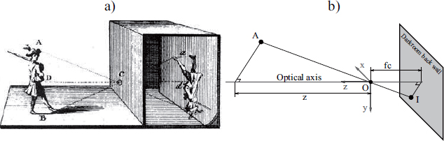
While photography captures fixed images, shortly after its arrival, scientists were using it to capture movement using an image sequence. Two approaches were developed to do so. In 1872, Muybridge proposed a system made up of multiple cameras (ranging between 12 and 24), triggered from a distance by a wire and placed along a track to take successive images of a galloping horse (see Figure 1.6(a)). In 1878, he developed the zoopraxiscope which displayed the successive images stored on a disk. In 1882, the French scientist Jules Marey [MAN 99] developed the photographic gun and then in the same year invented “chronophotography” in order to capture the movement of animals and humans. In contrast to Muybridge’s system, chronophotography involves a device with a single objective, fitted with a rotating shutter, which captures a series of movements through superposition on a single piece of film. To function, the subject must appear bright against a dark background (see Figure 1.6(b)). In 1889, this restriction was removed by allowing a transparent film to proceed jerkily, producing a sequence of up to 60 images per second.
1.2.3.3. Multiview 3D reconstruction
The idea of combining several images to obtain a projection of a spatial reconstruction is not new. For instance, photosculpture [BOG 81, SOR 00] proposed by François Willème (1830–1905) was inspired by two arts: photography and sculpture. The principal idea entails using photographies from several viewpoints to reconstruct a model of a portrait. The original technique positioned a system of 24 cameras placed at intervals of 15 degrees, directed toward a central point situated around 5 m away to take photographs of the model. The negatives were simultaneously produced to allow human subjects to be photographed. The images, projected successively by a lampascope on a translucent screen, were transferred via a pantograph by a potter using a clay block placed on a rotating base (see Figure 1.6(c)). The edges are then cut. The sculpture is retouched by the artist before its finalization. This technique has inspired a number of artists due to the realistic accuracy of the sculpture and the very short posing time for the subject.
Figure 1.6. a): Initial sequences of images with Muybridge’s multiview systems; b): Marey’s device superposing successive shots by a single camera; and c) the photosculpture procedure projecting 24 images on a screen connected to a pantograph
1.3. Stereopsis and 3D physiological aspects
3D perception, visual acuity and visual field, in which details are distinguished, as well as the distance at which these details are perceived (see Figure 1.7 and Chapter 16), are important characteristics in our visual sense. Taken independently from one another, each eye can be compared to a camera whose sensory layer corresponds to the retina. Focus (visual accomodation) is carried out by a deformation of the lens and the direction toward the point being focused on by the extraocular muscles. The concept of 3D and being able to perceive distance is primarily due to binocular vision. The human visual system [LEI 06] is, therefore, evidently a complex system which uses an enormous range of indices functioning in tandem, particularly when viewing 3D. These different sources of information are normally divided into two large categories: subjective sources, which include psychophysical, graphic and dynamic indices; and objective sources, which include ocular and stereoscopic information.
Figure 1.7. Physiological limits and description of the human visual field; Panum’s area indicates the area in which two images are fused to provide a single perception

1.3.1. Psychophysical indices
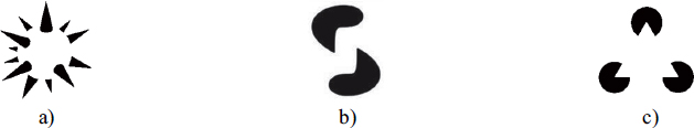
According to the Gestaltist3 theory [GUI 79, KOH 70], perception uses innate knowledge, memory and situational expectations, indicators which make perceptions that are genuinely sensed coherent. Each perceived scene is broken down into parts which are regrouped or reorganized. This theory relies on two basic principles: the distinction between foreground and background and the principles of regrouping. The brain therefore classifies, categorizes, makes sense of and regroups every tiny perception with others resembling it. The brain structures the indices in such a way that those which are small, regular or have a particular significance for us stand out against the background to create an overall structure. Each element is then perceived as a figure detached from the background, perceived as less structured and irregular. It is this foreground–background distinction that enables us to distinguish or recognize a familiar face in a crowd, as shown in Figure 1.8(a), a spiky sphere in Idesawa’s figure.
1.3.2. Monocular indices
Perception in relation to depth within a 3D scene by monocular vision uses a coherent range of visual indices at the same time, as described below:
– occlusion: an object partially obscuring another will necessarily be in front of the masked object;
– size and height in relation to objects: for objects with formal similarities, the observer infers their distances in relation to their size relative to the image on the retina. If they are smaller, they will be perceived as being further away;
– linear perspective: this relates to convergences toward specific points in the visual field, known as vanishing points, which appear in scenes with objects with regular edges or using motifs repeated along colinear axes;
– atmospheric diffusion: this corresponds to the decrease in contrast for distant objects. Distant objects appear more or less distinctly while closer objects are clear, giving a reinforced sensation of depth;
– shadowing: it provides information not only about the shape of an object but also its position in relation to the shadow position and size.
Figure 1.8. Gestalt and perception with: a) Idesawa’s spiky sphere; b) Tse’s worm; and c) the Kanizsa triangle
To this series of static indices, we should also add dynamic indices, such as motion parallax, which provide information about visible objects’ relative distances by changes in direction.
1.3.3. Ocular indices
These indices refer to closely related ocular movements which allow us to see from different distances. This adaptation functions using a combination of vergence movements (fusion convergence) and focus (deformation of the lens). This convergence-focus reflex is an important process in depth perception which, paradoxically, can cause significant conflicts (see Chapter 16). Indeed, as shown in Figure 1.9, the synkinetic nature of this reflex allows us to focus and converge at a single point during normal visual exploration. The problem arises, however, when we want to reproduce the sensation of depth perception using an image displayed on the surface of a 3D screen. In this case, there is a dissociation of focus and convergence movements, which may effectively induce visual discomfort.
Figure 1.9. Visual exploration using the convergence-focus reflex (![]() the focus point,
the focus point, ![]() the convergence point)
the convergence point)

1.3.4. Binocular indices
Binocular or stereoscopic vision provides access to information known as retinal disparity which can be represented by the difference between the images taken from the left and right eyes (see Figure 1.10). This information, processed in the primary visual cortex, reconstructs 3D or, in other words, depth. It is this principle, also known as stereopsy, which allows us to recreate binocular vision using artificial means. This geometric model of binocular depth perception is described in further detail in Chapter 3 first within the context of stereoscopy, and then in Chapter 4 where it is extended to multistereoscopy. In both cases, problems of perceived depth distortions are examined.
Figure 1.10. Fusion and disparity in retinal images. Disparity accounts for the fact that an image is projected onto different places on the two retinas. More than being a mere stimulus to vergence movements, the disparity between images from the two eyes provides indications about the depth of objects in the scene

1.4. 3D computer vision
As an algorithmic representation of human vision, computer vision or artificial vision, is a discipline whose theoretical basis was first proposed during the 1960s. This processing paradigm of visual information generally operates according to two axes: ascending, related to changing sensory information into an abstract representation using a series of 3D primitives, for example, or descending, when it relates to verifying the primitives taken from the image from a series of known objects.
In 1982, one of the first formalisms of this theory related to 3D vision was proposed by D. Marr [MAR 82]. This computation model can be formally defined as follows:
– From one or several images by extracting characteristics which describe the bi-dimensional attributes of a representation known as a primal sketch.
– This primal sketch is the input for a number of more or less dependent processes which evaluate the local 3D properties related to the scene. This new representation, qualified by 2.5D, remains focused on the observer. These processes can often, depending on context, operate on a sequence of images if it relates to analyzing movement, on a couple of images in case of stereovision or simply a single image when, for example, it entails defining an outline on the basis of geometric, statistical, photometric or colorimetric information, etc.
– The 2.5D sketch is then compared with 3D information to construct a description of the scene in terms of objects and in relation to other objects. This is therefore a scene-focused description which no longer depends on the observer.
In 1991, E.H. Adelson and J.R. Bergen [ADE 91] proposed an alternative to modeling visual information of a real scene by applying a functional representation known as “plenoptic”, noted as ![]() (see equation [3.7] in Chapter 3) which defines at each time t and at each point p in the space with the coordinates (x, y, z), the energy at the wavelength λ traveling in any direction
(see equation [3.7] in Chapter 3) which defines at each time t and at each point p in the space with the coordinates (x, y, z), the energy at the wavelength λ traveling in any direction ![]() . This representation has the benefit of providing a fixed framework for problems such as capture, representing and synthesizing visual content. However, this form remains fairly difficult to use, as a result of which simplified forms of reproducing 4D light fields, or lumigraphs, have emerged. This model is also the basis for a body of work known as “image based” which is normally known as image-based modeling and rendering (IBMR) and/or computational photography.
. This representation has the benefit of providing a fixed framework for problems such as capture, representing and synthesizing visual content. However, this form remains fairly difficult to use, as a result of which simplified forms of reproducing 4D light fields, or lumigraphs, have emerged. This model is also the basis for a body of work known as “image based” which is normally known as image-based modeling and rendering (IBMR) and/or computational photography.
More recently, Dai et al. [DAI 10] proposed another approach known as Vision Field Calculating [DAI 11], which encompasses all research related to filming and reconstructing real-life scenes.
This classification relies on a parametric space (see Figure 1.11) where 3D represents time, viewpoints and lighting. One point in this space corresponds to the conditions for capturing an image. Capture can be considered as taking a sample of the scene while analysis and synthesis are combined in what we can call its reconstruction.
Figure 1.11. Thematic classification in the Vision Field Calculating Space (according to [DAI 10])
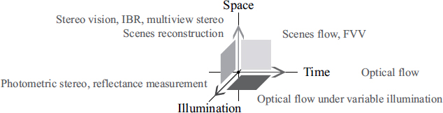
As a result, image capturing strategies in the subspace (or plane) time/viewpoints can also result in multiple viewpoint capture systems, a large number of which are examined in Chapter 3. Several acquisition solutions relate to the viewpoint/lighting planes which are also used to digitalize the optical properties of static objects’ surfaces.
Alongside reconstruction, we can similarly identify classes of solutions associated with axes or planes in this space. Optical flow approaches, for example, enter into the time axis, stereovision (from two or more view points) or the light field rendering for a static scene under constant lighting in the viewpoints axis. In the time/viewpoints plane, this relates to reconstructing a dynamic scene using videos taken from several view points, such as free-viewpoint video, 3D motion capture or 4D reconstruction. The viewpoints/lighting covers problems of multi-lighting stereovision and 3D relighting in static scenes. The approaches relating to the time/lighting plane are difficult to implement because it is difficult to use multi-lighting conditions in temporal capture.
1.5. Conclusion
In this chapter, we have examined the different fundamentals of 3D video: historical, physiological in relation to human vision or mathematics and its extension to 3D computer vision. These principles are the basis for the subsequent scientific formalizations and technological developments presented in the following chapters.
Beyond this, all these subjects are treated in further detail in a number of works published in recent years, specifically the works of [CYG 11, HAR 04, JAV 09, LUK 10, MAT 12, RON 10, SCH 05, SZE 10 and WOH 13].
1.6. Bibliography
[ADE 91] ADELSON E.H., BERGEN J.R., “The plenoptic function and the elements of early vision”, in LANDY M.S., MOVSHON A.J., (eds), Computational Models of Visual Processing, MIT Press, Cambridge, MA, pp. 3–20, 1991.
[ALA 07] ALATAN A., YEMEZ Y., GUDUKBAY U., et al., “Scene representation technologies for 3DTV – a survey”, Circuits and Systems for Video Technology, IEEE Transactions on, vol. 17, no. 11, pp. 1587–1605, 2007.
[ALH 21] ALHAZEN, latin name of IBN AL HAYTHAM, Kitab al-Manazir, in latin De Aspectibus, or Opticae Thesaurus: Alhazeni Arabis, in English Treaty of Optics, Cairo, Egypt, pp. 1015–1021, 1921.
[ARI 36] ARISTOTLE, Problemata, vol. 15, Circa-350 B.C., W.S. HETT (transl.), Harvard University Press, Cambridge, 1936.
[BOG 81] BOGART M., Photosculpture, Art History, vol. 4, no. 1, pp. 54–65, 1981.
[BRE 56] BREWSTER D., The Stereoscope; its History, Theory, and Construction, with its Application to the Fine and Useful Arts and to Education: With Fifty Wood Engravings, John Murray, 1856.
[CAR 56] CARDANO G., De la subtilité et subtiles inventions, L’Angelier, Paris, 1556.
[CYG 11] CYGANEK B., SIEBERT J., An Introduction to 3D Computer Vision Techniques and Algorithms, Wiley, 2011.
[DAI 10] DAI Q., JI X., CAO X., “Vision field capturing and its applications in 3DTV”, Picture Coding Symposium (PCS), IEEE, pp. 18–18, 2010.
[DAI 11] DAI QI., WU D., LIU Y.T., University (Beijing, CN), June 2011–www.freepatentsonline.com/y2011/0158507.html, Patent 20110158507.
[GUI 79] GUILLAUME P., La psychologie de la forme, Champ Psychologique, Flammarion, 1979.
[HAR 04] HARTLEY R., ZISSERMAN A., Multiple View Geometry in Computer Vision, Cambridge Books Online, Cambridge University Press, 2004.
[JAV 09] JAVIDI B., OKANO F., SON J., Three-Dimensional Imaging, Visualization, and Display, Signals and Communication Technology, Springer Science+Business Media, LLC, 2009.
[KOH 70] KOHLER W., Gestalt Psychology: An Introduction to New Concepts in Modern Psychology, Black and Gold Library, Liveright, 1970.
[KUB 07] KUBOTA A., SMOLIC A., MAGNOR M., et al., “Multiview imaging and 3DTV”, Signal Processing Magazine, IEEE, vol. 24, no. 6, pp. 10–21, 2007.
[LEI 06] LEIGH R., ZEE D., The Neurology of Eye Movements, Contemporary Neurology Series, Oxford University Press, 2006.
[LIP 08] LIPPMANN G., “Épreuves réversibles donnant la sensation du relief”, Journal of Theoretical and Applied Physics, vol. 7, no. 1, pp. 821–825, 1908.
[LUK 10] LUKAC R., Computational Photography: Methods and Applications, Digital Imaging and Computer Vision Series, Taylor & Francis Group, 2010.
[MAN 99] MANNONI L., Le grand art de la lumière et de l’ombre, Nathan University, 1999.
[MAR 82] MARR D., Vision: A Computational Investigation into the Human Representation and Processing of Visual Information, Henry Holt and Co., Inc., New York, 1982.
[MAT 12] MATSUYAMA T., NOBUHARA S., TAKAI T., 3D Video and Its Applications, Springer, London, 2012.
[MIC 11] MICHEL B., La stéréoscopie numérique: Tourner, éditer, diffuser, imprimer, projeter, Eyrolles, 2011.
[MOH 00] MOHISTS, under the pseudonym MO ZI, Mo Jing, China, Circa 400 B.C.
[RON 10] RONFARD R., TAUBIN G., Image and Geometry Processing for 3D Cinematography, Springer, 2010.
[ROS 08] ROSENBLUM N., A World History of Photography, 4th ed., Abbeville Press, 2008.
[SCH 05] SCHREER O., KAUFF P., SIKORA T., 3D Videocommunication: Algorithms, Concepts and Real-time Systems in Human Centred Communication, Wiley, 2005.
[SMO 07] SMOLIC A., MUELLER K., STEFANOSKI N., et al., “Coding algorithms for 3DTV – a survey”, Circuits and Systems for Video Technology, IEEE Transactions on, vol. 17, no. 11, pp. 1606–1621, 2007.
[SOR 00] SOREL P., “Photosculpture: the fortunes of a sculptural process based on photography”, in REYNAUD F., TAMBRUN C., TIMBY K. (eds), 3D: From Stereoscopy to Virtual Reality, Paris, 2000.
[SZE 10] SZELISKI R., Computer Vision: Algorithms and Applications, Texts in Computer Science, Springer, 2010.
[VAN 11] VANVOLSEM M., Chapter 1: Strip Photography and its Historical Context: A Camera Mechanism, Invention and Re-invention, Leuven University Press, 2011.
[VIN 19] DA VINCI L., Codex Atlanticus, 1478–1519, set of 1119 leaflets.
[WOH 13] WOHLER C., 3D Computer Vision, Springer, London, 2013.
1 Among other things, we can thank Girolamo Cardano for his eponymous resolution method for quartic and cubic equations, the first use of negative and subsequently imaginary (or, in his words “fictive”) numbers, previously discovered by the Hindus and then by the Fibonacci in the 13th Century, a first formulation with Raphael Bombelli of complex numbers (under the name “impossible numbers”), major, pioneering contributions to statistics, probabilities, cryptography (the Cardan grille), numerous therapeutic and diagnostic contributions to medicine, Cardan suspension and joints in mechanics, and the Baguenaudier (also known as Cardano’s rings), in addition, to the photographic lens.
2 House of Wax in 1953, http://en.wikipedia.org/wiki/House_of_Wax_(1953_film); Creature from the Black Lagoon in 1954, http://en.wikipedia.org/wiki/Creature_from_the_ Black_Lagoon, etc.
3 This theory takes its name from the German verb “Gestalt” which means shape.