Chapter 3
Multiview Acquisition Systems
3.1. Introduction: what is a multiview acquisition system?
Multiview acquisition, the focus of this chapter, relates to the capture of synchronized video data representing different viewpoints of a single scene. In contrast to video surveillance systems, which deploy multiple cameras to visually cover a large-scale environment to be monitored with little redundancy, the materials, devices or systems used in multiview acquisition are designed to cover several perspectives of a single, often fairly restricted, physical space and use redundancy in images for specific aims:
Depending on the final application, the number, layout and settings of cameras can fluctuate greatly. The most common configurations available today include:
Alongside these purely video-based solutions, hybrid systems adding depth sensors (Z-cams) to video sensors are also interesting. The captured depth can theoretically provide direct access to the majority of desired postproductions. The number of video sensors as well as depth sensor resolution and spatial limitations can, however, restrict some of these postproduction processes. These hybrid systems, however, will not be examined within this book.
All these materials share the need to synchronize and calibrate (often even with geometric and/or colorimetric corrections) information captured by different cameras or Z-cams, and often have different accompanying capabilities regarding:
This chapter introduces the main configurations mentioned above in a purely video multiview capture context, using notable practical examples and their use. We will also propose links to databases providing access to media produced by devices within each category.
3.2. Binocular systems
3.2.1. Technical description
Capturing binocular video, also known as stereoscopy or, more recently “3D stereoscopy” (3DS), requires the use of two cameras2 connected by a rigid or articulated mechanical device known as a “stereoscopic rig”. The images taken can be projected either on a stereoscopic display device (such as a cinema screen or a 3D television, most commonly) [DEV 10], or used to extract the scene’s 3D geometry, in the form of a depth map, using stereo correspondence algorithms.
3.2.1.1. The shooting geometry
Filming is carried out using two cameras with the same optical parameters (focal length, focus distance, exposure time, etc.), pointing roughly in the same direction, orthogonal to the line connecting their optical centers (which is known as the baseline). The optical axes can be parallel or convergent.
Ideally, to simplify stereoscopic correspondence, the two optical axes must be strictly parallel, orthogonal to the baseline, and the two image planes must be identical. In this situation, the corresponding points have the same y-coordinate in both images. However, if the cameras are convergent (i.e. the optical axes converge at a finite distance) or if the alignment is approximate, the images taken by the camera can be rectified (see section 5.4) to get back to the ideal situation. Rectification is therefore an important postproduction phase for stereoscopic films (see section 3.2.2.1).
The main geometric parameters for stereoscopic recording and stereoscopic visualization are shown in Figure 3.1. b, W and H are the parameters of the stereoscopic camera and Z is the distance from a 3D point to the plane passing through the stereoscopic baseline and parallel to the image planes. The triangles MlPMr and ClPCr are homothetic. As a result: ![]() . This allows us to simply express the relations between the stereoscopic disparity d, expressed as a fraction of the image’s width W and the distance Z, similar to that shown in Chapter 7:
. This allows us to simply express the relations between the stereoscopic disparity d, expressed as a fraction of the image’s width W and the distance Z, similar to that shown in Chapter 7:
Figure 3.1. Geometry of the stereoscopic shooting device and that of the stereoscopic display device can be described by the same low number of parameters

3.2.1.2. Perceived geometric distortions
If stereoscopic video is designed to be projected onto a stereoscopic display device whose parameters are b′, W′ and H′, the depth Z′ perceived by stereoscopy3 can be calculated according to the disparity d (equation [3.2]). By eliminating the disparity d from [3.1] and [3.2], in [3.3] we obtain the relation between the real depth Z and the perceived depth Z′, which will be applied to the multiscopic example in Chapter 4:
[3.3] ![]()
There is ocular divergence when ![]() i.e. when the on screen binocular disparity is larger than the viewer’s interocular. In general, real objects that are very far away.
i.e. when the on screen binocular disparity is larger than the viewer’s interocular. In general, real objects that are very far away. ![]() are perceived at a finite distance or create divergence, depending on whether
are perceived at a finite distance or create divergence, depending on whether ![]() is smaller or greater than 1. We then consider that an ocular divergence in the order of 0.5a is acceptable for short durations, and that this trick is used by stereographers to artificially augment the depth available behind the movie screen.
is smaller or greater than 1. We then consider that an ocular divergence in the order of 0.5a is acceptable for short durations, and that this trick is used by stereographers to artificially augment the depth available behind the movie screen.
In the case of 3D television, the disparity limits due to the conflict between convergence and accommodation [EMO 05, UKA 07, YAN 04] render large (either positive or negative) disparities uncomfortable. The depth of focus of the human eye is in the order of approximately 0.3 δ (diopters) in normal situations4, which, on a screen placed 3 m away, gives a depth of focus ranging from ![]() to
to ![]() . In practice, TV production rules are much stricter. 3DTV programs are produced with disparities ranging from −1% to +2% of the screen width5 to remain in this comfort zone6, with disparities temporarily ranging from −2.5% to +4%, which completely prevents reaching the divergence limit on private projection devices.
. In practice, TV production rules are much stricter. 3DTV programs are produced with disparities ranging from −1% to +2% of the screen width5 to remain in this comfort zone6, with disparities temporarily ranging from −2.5% to +4%, which completely prevents reaching the divergence limit on private projection devices.
We can see also that the situation where the perceived depth is strictly identical to the real depth (Z′ = Z) can only be obtained if all parameters are equal, which is known as the “orthostereoscopic” configuration (this configuration is often used for IMAX 3D films since the geometry of the projection device is known beforehand).
For a 3D fronto-parallel plane placed at a distance Z, we can calculate the scale factor s between the distances measured within this frame and the distances in the convergence plane: s = H/Z. We can also calculate the image scale factor σ′, which explains the extent to which an object placed at a depth of Z or the disparity d is perceived as being enlarged (σ′ > 1) or reduced (σ′ < 1) in the directions X and Y with respect to objects in the convergence plane (Z = H):
Of course, for objects in the screen plane (d = 0), we have σ′ = 1. The relation between Z and Z′ is linear if, and only if, W/b = W ′/b′, in which case σ′ = 1 and Z′ = ZH′/H. We refer to this configuration as “orthoplastic” configuration (an orthostereoscopic configuration is, above all, orthoplastic).
A small object with a width of ∂X and a depth of ∂Z, placed at Z, is perceived as an object with the dimensions ∂X′ × ∂Z′ at a depth of Z′, and the roundness factor ρ measures how much the object’s proportions are modified:
In the screen’s frame (Z = H and Z′ = H′), the roundness factor can be simplified as:
A roundness factor equal to 1 indicates that a sphere is perceived exactly as a sphere, a smaller roundness factor indicates that it is perceived as a sphere flattened in the depth direction and a larger roundness factor indicates that it is perceived as an ellipsoid stretched in the depth direction. The roundness of an object in the screen plane is equal to 1 if, and only if, b′/b = H′/H. In order for this to be the case in the whole space, it is necessary that b′/b = W′/W = H′/H. As a result, the only geometric configurations that preserve roundness everywhere are identical to the display configuration up to a scale factor; these are “orthoplastic” configurations. Even if the geometry of the display device is known during filming, this imposes strict constraints on how the film is shot, which can be very difficult to follow in different situations (i.e. when filming sports events or wildlife documentaries). On the other hand, since the viewer’s interocular b′ is fixed, this indicates that a film can only be projected on a screen of a given size W′ placed at a given distance H′, which is in contradiction with the large variability of projection devices and movie theaters. We therefore refer to “hyperplastic” or “hypoplastic” configurations when the roundness is larger or smaller than 1, respectively. The roundness in the screen plane also increases when we move away from the screen and it is independent of screen size, which is counterintuitive; the majority of viewers expect to perceive “more 3D” when approaching a large screen.
Another important point to make is that a film, shot to have a specific roundness for a cinema screen positioned 15 m away on average, will see its roundness divided by 5 once projected on a 3DTV screen placed 3 m away, which, in part, explains the current dissatisfaction of 3DTV viewers. This effect can be counter balanced by specific post production for media designed for private viewing (home cinema), e.g. for 3D Blu-ray, although there are few titles that benefit from this treatment. Of course, this reduction in roundness is, in part, compensated by monoscopic depth cues. Besides, the roundness used in 3D cinema films is, in reality, between 0.3 and 0.6, depending on the desired dramatic effect [MEN 09], in order to favor the viewer’s visual comfort.
3.2.2. Principal uses
3.2.2.1. Cinema and 3D television
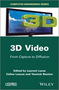
Cinema and television rigs are, for the most part, heavy systems that often use a semi-reflective mirror to obtain interocular distances for the camera shorter than the diameter of the lens [MEN 11] (see Figure 3.2 (a)). Today a number of manufacturers produce compact semi-professional integrated stereoscopic cameras but their field of use is reduced, notably due to the fact that the interocular of these cameras is generally fixed while stereoscopic filming requires an adequate tuning of all stereoscopic parameters; merely adding a second camera alongside the first is not enough for 3DS filming.
Figure 3.2. Examples of rigs: a) Binocle Brigger III in a studio configuration, a robotized rig for 3DTV; b) a heliborne rig with four cameras used by Binocle for the film La France entre ciel et mer
3.2.2.1.1. Stereoscopy, a new and different art
2D cinema, in order to exist, has (1) to study the function of the brain in order to trick it into believing that a series of fixed images are really showing movement, (2) to survey, through experience gained from photography, the techniques that enable this illusion and develop a complete cinematographic chain and (3) to invent the parameters of a new art, which is the role of artists involved in the production of films, followed by engineers producing tools enabling these new artistic practices.
Stereoscopy is both a continuous evolution and a turning point in cinematography due to the fact that, as with photography, it must use current techniques and develop others. To do so, it is essential to:
The cinematographic parameters on which traditional filming relies are well known. However, the rules that govern the stereoscopic parameters in order to create this new illusion have not yet been established. Based on the way the human visual system works, they should simulate (1) how convergence is, in general, coupled with accommodation, and (2) 3D vision resulting from the distance between both eyes, a parameter that varies slightly throughout the lifespan of each individual and between individuals.
However, simply shooting with an interocular equal to the average interocular of a population sample cannot, contrary to some ophthalmological studies, be considered sufficient. Indeed, stereoscopy uses these two parameters (interocular and convergence) to create emotion and feeling, exactly as the lenses used on a camera do not try to reproduce human perspective vision but reform it depending on the medium used. If we push these variations in distance to the extreme, on the one hand, we have the value 0, which corresponds to two identical 2D images and, on the other hand, interaxial distances without any relationship with the geometry of the human visual system. NASA, for example, has produced stereoscopic images of Earth with a distance of almost 70 m between the two viewpoints.
To create a rig, the interocular distance must be able to vary from 0 to the greatest usable value for some kind of scene. In general, for a standard configuration for comedy, a variation from a few millimeters to several centimeters corresponds to 90% of needs for fiction-based filming. As a result, rigs used for close-ups have interocular ranges between 0 and 100 mm. Lastly, for long-distance shots of clouds, for example, the distance between the two cameras may even extend to several meters and the side-by-side rigs are often adapted to the specific needs of a given shot.
3.2.2.1.2. Computer-assisted production
While the rules for recreating a universe in 3D have been known since the 19th Century, the possibility of stereoscopic filming using rigs is much more recent and involves the use of a computer to analyze video streams and correct any potential faults. Given the fact that no mechanical, optical or electronic device is perfect, it is imperative to correct the recorded images as precisely as possible with a 3D corrector, in real time for television and in postproduction for cinema. This was enabled by the invention of digital images, which can correct each pixel individually.
3.2.2.1.3. Robotized rigs
A rig must use synchronized cameras and lenses with perfectly synchronized and calibrated zoom, point and diaphragm movements. The rig itself is robotized and contains motors that adjust distance and convergence in real time, as well as yaw/pitch/roll adjusting plates used to converge the two optical axes (the optical axes must be concurrent). In some cases, rigs have been used with more than two cameras, as was the case for the French language film La France entre ciel et mer [France between sky and sea], which was filmed by Binocle with four cameras on a helicopter (see Figure 3.2). In this case, the matching of four zooms and adjusting plates with four cameras demanded a huge degree of expertise since all optical centers had to be aligned as closely as possible.
Examples of materials used to pilot the rig, and to directly control the geometric and photometric quality and faults include TaggerLive and TaggerMovie by Binocle7, Stereoscopic Analyzer (STAN) by Fraunhofer HHI, Stereoscopic Image Processor (SIP) by 3ality Technica8, the real-time correction processor MPES-3D01 – often referred to as “3DBox” – by Sony and Pure by Stereolabs9.
3.2.2.1.4. Stereoscopic postproduction
Postproduction tools have also been adapted to 3D cinema and algorithms specific to stereoscopy have been integrated into this software such as rectification, viewpoint interpolation and depth modifications, 2D to 3D conversion, color balancing of two streams and production of a depth map for 3D scene compositing. These tools include the Ocula plugins suite for Nuke (The Foundry)10, DisparityKiller (Binocle), and Mistika Post (SGO)11.
3.2.2.2. Depth reconstruction
Binocular systems designed to produce a stereoscopic reconstruction of “partial” 3D data12 are generally much simpler than those used for cinema or television. These are most often lightweight systems that are small, consume little energy and can be used by a vehicle or mobile robot, for example, and they almost always have a fixed interocular distance in order to simplify their calibration.
The majority of these systems use monochrome cameras, since brightness alone is sufficient for stereoscopic correspondence, but color may bring additional functions such as the possibility of using color for segmentation tasks (such as skin color) or object recognition. Cameras used in this kind of system generally use a single sensor, since the use of color (by the way of a Bayer matrix filter) results in a loss of spatial resolution in images and therefore affects the precision of reconstructed depth.
The choice of the optimal interocular distance value for reconstruction is a disputed subject but a simple rule of thumb can predict the final precision. The precision of the disparity d obtained by the stereoscopic correspondence algorithm can be presumed constant in the image (let us say 0.5 pixels). The error in the reconstructed depth Z is obtained by deriving equation [3.1]: ∂Z/∂d = bHW/(b – dW)2, and ∂Z/∂d = Z2W/(bH). The error increases with the square of the distance and theoretically decreases with the interocular distance b, so that theoretically the larger the interocular distance, the better the precision in depth reconstruction. However, when we increase the distance, stereoscopic matching between the images is more difficult and the precision of disparity d is strongly degraded when the b/H value increases. Experience shows that, as a rule of thumb, a b/H value between 0.1 and 0.3 represents a reasonable compromise between ease of stereoscopic correspondence and precision in depth reconstruction.
Any pair of rigidly linked and synchronized cameras can be used13 to reconstruct depth using stereoscopic correspondence algorithms (the OpenCV software library provides calibration functions, stereoscopic correspondence and simple 3D reconstruction algorithms).
Commercial off-the-shelf systems are also available. They have the advantage of being solidly constructed, precalibrated or easy to calibrate, and sometimes propose optimized stereoscopic correspondence algorithms, using the CPU or a dedicated FPGA. Point Grey has developed the Bumblebee system14 using two or three cameras with different sensors or focal length options and a Software Development Kit (SDK) for calulating depth maps on the CPU. The Tyzx DeepSea stereo vision system15, proposed with several interocular distance options, uses a FPGA and a PowerPC CPU to compute disparity, and transmits the 3D data via ethernet.
Focus Robotics has developed nDepth16, with a fixed interocular distance of 6 cm, and a factory-calibrated monochrome sensor. Videre Design17 has created stereo vision systems with fixed or variable interocular distances, with disparity computation carried out by the Small Vision System software (developed by SRI) or by a special chip (Stereo On Chip (STOC)). Surveyor Corporation18 sells the Stereo Vision System (SVS), which is a low-cost solution for stereo with options such as embedded image capture, motorization and Wi-fi transmission, based on an open-source firmware.
3.2.3. Related databases
The European QUALINET project19 has collated and classified a number of multimedia databases with a specific section dedicated to 3D Visual Content Databases directing users toward databases of fixed images or multiview stereoscopic video. The MOBILE-3DTV project20 also contains a number of reference stereoscopic sequences. Other high-quality databases are also made available because of IEEE-3D Quality Assesment Standard Group21 and the Sigmedia team at Trinity College Dublin22.
3.3. Lateral or directional multiview systems
3.3.1. Technical description
This section examines systems and devices with close-together (relative to the scene being filmed) multiview sensors, often distributed evenly along a curve (whether rectilinear or not) or on a grid (flat or not). Thus, there are systems designed by mechanical assembly (linear or matricial) and synchronization of usual cameras as well as devices constructed by integrating optoelectronic components situated in order to provide the desired layout of viewpoints and then synchronized using specifically designed electronics. Lastly, these capture tools differ by the target use of the multiview media they capture (direct multiscopic visualization, FTV, reconstruction, refocus, etc.), which has a direct impact on the compromise between the number of views and their resolutions to maintain an acceptable volume of pixels to be captured, transmitted and stored.
These close multiview capture tools (either assembled or integrated) are often known as “camera arrays” (grids or linear layouts of cameras or viewpoints) and “plenoptic” systems or cameras. Camera arrays are generally focused on capturing multiple images with significant resolution for the depth reconstruction and 3D and/ or interactive visualization (FTV), while plenoptic systems generally aim to capture the “light field”, and are more balanced in terms of the number of views and resolution to extract interpolated views (FTV) or variable focus images (refocus) as well as, sometimes, depth reconstructions. This classification is more nuanced than it seems because the similarity of their shooting geometries and improvements in shooting and pixel processing volumetric capabilities tend to bring closer those ratios number of views/number of pixels per view ratios and therefore mean that intended applications are accessible by both types of system. This classification could, however, soon be a historical artefact related to the appearance in successive waves of these technologies as well as their original objectives.
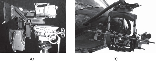
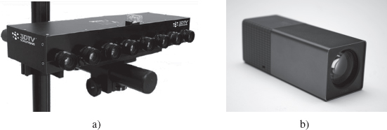
Undeniably, the first devices proposed fell within the class of linear viewpoint arrangements. Initially limited to capturing static scenes (in terms of composition as well as lighting), the very first systems achieved multiple perspective captures by controlling sequential positions of a still camera, as developed by Stanford University [LEV 96]. They were quickly overtaken by multisensor devices taking images of the same dynamic scene simultaneously, such as that proposed by Dayton Taylor in 1996 [TAY 96], and/or in low-level and controlled desynchronization, such as the system developed by Manex Entertainment for the film The Matrix. The majority of these devices were often designed and build specifically for their desired function: the MERL 3DTV project by Mitsubishi [MAT 04] positioned 16 cameras on a rail to produce multiscopic content designed for their ad hoc autostereoscopic screens while the University of California in San Diego, with Mitsubishi [JOS 06], used a rail with eight cameras for an automatic video matting application. Several prototypes of integrated devices have also been proposed for specific applications. We can, for example, cite the cameras with eight viewpoints developed in Reims, France [PRE 10], which are illustrated in Figure 3.3, and which were specifically designed to produce multiscopic content with controlled distortion (see Chapter 4) for autostereoscopic screens on the market.
Figure 3.3. Examples of integrated cameras: a) a Cam-Box prototype camera with eight integrated perspectives developed by 3DTV Solutions and the University of Reims and b) the Lytro plenoptic camera
These linear layouts have, in addition, also been extended by several laboratories to more complex systems of 2D grids of cameras. The most well known is probably that created by Stanford University23 [WIL 05], which has been used for multiple applications, notably aimed at FTV and refocus. It is composed of a variable number of cameras (usually more than 100) organized according to various configurations in planar or piecewise planar 2D grids. Another 2D grid, albeit irregular, has been developed by the Carnegie Mellon University [ZHA 04] with 48 cameras in individual horizontal and vertical positions controlled to optimize the calculation of depth in order to generate the desired perspective (FTV). We can also cite Sony in partnership with Columbia University [NOM 07], which have proposed flexible and stretchable 1D and 2D grids, composed of elastic supports on which 20 cameras are fixed in regular positions (at rest state). The deformation of the support therefore modifies the system’s configuration to adapt to the situation and the desired requirements (more or less panoramic mosaicking in [NOM 07]).
The emergence of grids has also enabled research dealing with ray-space associated with plenoptic function, notably summarized by [ADE 91]. This plenoptic function (an aggregation of the Latin plenus – complete – and optics) is the function that gives the light intensity of all the rays in a scene. Yielding real values, it is defined for seven real variables; three for the position of a point of the ray, two for its 3D direction of propagation, one for the wavelength from which we measure intensity and the last for the point in time of this measure:
Usually, this function is reduced to five variables by externalizing the wavelength in the result that becomes a spectrum and by considering the intensity to be constant at the time of measure along the whole length of the ray24. According to this hypothesis, all the points in the ray deliver almost the same spectrum at the time studied and we can therefore reduce this redundancy by suppressing one of the space variables. In practice, we commonly select coplanar points by no longer “managing” the rays parallel to this ray-capturing plane. This gives:

The domain’s dimension can again be reduced to four by fixing the time of study or by transferring it in the result that becomes a temporal spectrum:

Digitalizing the reduced plenoptic function involves spatial, angular, spectral and temporal windowing and sampling operations followed by quantification of the intensities that limit the domain as well as the value space. These operations create a temporal series of 4D digital signals indexed by the indices i, j (connected to x, y) from the capture points arranged in a grid and the coordinates s, t of the image pixel captured (in i, j), representative of the direction φ, θ of the ray measured in i, j, s, t. For each sample, they contain a set of intensities quantified for a discrete number of spectral bands (generally three – red, green, blue (RGB)). These light fields can be easily obtained from the data captured by a camera array by simply stacking up the views captured according to the grid’s layout:
[3.10] ![]()
The growing attraction for this multiview capture representation and, specifically for its resulting models and applications (FTV, refocus, to name but a few), has led to the arrival of dedicated optics, such as that proposed by Todor Georgiev from Adobe-Qualcomm25, and integrated solutions, such as the “plenoptic cameras” proposed in recent years by companies such as Raytrix26 or Lytro27 (see Figure 3.3). These cameras generally include a microlens grid in front or behind the lens in order to separately capture, after deviation, the light rays that are combined in a standard camera (see Figure 3.4 for an illustration with a lenticular array at the back wall of the darkroom). If the object is captured in the focus plane (example B in Figure 3.4), instead of a clear pixel, we obtain a homogenous microimage that is synonymous with the object’s position being in the focus plane. Otherwise (examples A and B), we obtain, instead of a blurred pixel, a local sampling of the object that, coupled with those of the neighboring capture positions, allows reconstructing the points outside the focus plane. Other approaches, notably that by Mitsubishi [VEE 07]28, replace the lenticular array with a printed mask similar to parallax barriers. As a result, the debate between masks and microlenses, well known with autostereoscopic displays, also applies to plenoptic cameras.
Figure 3.4. Differences between standard and plenoptic cameras: from above (axes x, j, s) or the side (axes y, j, t) the rays converging as a single point at the back wall of the darkroom are summed in the first and differentiated by refraction and sampling in the second

There has also been a recent tendency to miniaturize small grids within new integrated components, designed specifically for mobile terminals. The Californian company Pelican Imaging has produced a 5 × 5 microgrid component, which is the size of a current monoview sensor29.
3.3.2. Principal uses
Linear layouts of different viewpoints allow, by simple selection (or even interpolation) of a specific viewpoint, the effect of camera movement around a frozen or slow-motion scene. These technologies, known as bullet time, were largely brought to the fore in 1999 by the film The Matrix. It has since been used by a number of companies using more or less integrated proprietary systems that can be used with varied and occasionally surprising applications such as surfing30.
With the emergence of multiscopic visualization devices (see Chapter 14), the question of creating adapted content using real capture has been developed, notably leading to several improvements in camera arrays. Linear layouts have also focused on autostereoscopic devices with a simple horizontal parallax. Similarly, grids have also been used for double parallax devices, known as “integral imaging displays” in reference to its precursor, “integral photography” proposed [LIP 08b] and then experimentally demonstrated [LIP 08a] in 1908 by Gabriel Lippmann.
The generation of intermediary viewpoints (FTV, “image-based rendering” (IBR)) also had a strong influence on the emergence of different camera arrays. This technology is somewhat an extension of the frozen time virtual camera technique using camera position interpolation. Its implementation is, however, different and relies either on a depth reconstruction to project the available views on the virtual camera (see Chapter 9) or on a planar section of the light field (with the real, coordinates i, j fixed), yielding a digital signal that samples the reduced plenoptic function according to equation [3.10].
The strong redundancy of close-together multiple perspective captures in a single scene can provide a depth reconstruction with increased reliability. As the quality of both depth maps (or disparity maps with parallel geometry capturing) and occlusion detection is essential in related applications (such as FTV and AR), a number of teams have studied the opportunity to use these strong redundancies which imply additional new challenges. Multiple solutions have been proposed, seeking coherence between multiple binocular matches or directly examining multiocular matches across all views. Regardless of the approach, managing occlusions, which is accessible in multiocular vision, is an opportunity that remains difficult to manage. Chapter 7 provides a more detailed description of this area.
Similarly, the availability of strongly redundant views allowing for a global matching process has been used (see Chapter 19) to create HDR capturing devices by postprocessing views captured with moderate but varied dynamic from different viewpoints. The allocation of different dynamic ranges to viewpoints is obtained by neutral filters of different densities or by distinct exposure time settings.
To conclude, let us present an example of application of multiview capture, either by grids or plenoptic cameras, which is surprising since the notion of depth of field, a crucial aspect of photography, seemed definitely set at shooting. The numerous multiview captures as well as ray-space modeling have given rise to a flurry of activity relating to a new opportunity with highly promising possibilities: the choice to refocus postcapture. This includes, for example:
3.3.3. Related databases
Without attempting to provide an exhaustive list, there are a number of databases created using the devices discussed in this section. The University of California in San Diego and Mitsubishi31 deliver some captures in a linear layout with eight-view videos and a series of 120–500 still images. The Light Fields library at the University of Stanford32 is full of highly varied multiple scenes captured in high resolution, often from several hundred viewpoints, created by moving the camera on robotized arms or the Stanford grid. This information is available as raw or modified data with calibration information and the possibility of interacting online with their light field form by selecting a perspective and handling refocus (choice of shutter and focus plane). This library completes and surpasses its predecessor33, which proposed less complex series, both in terms of the number of views as well as their resolution. A simpler example is also available on Todor Georgiev’s site34, which contains a number of plenoptic images with several tens of millions of rays. Lastly, the University of Heidelberg maintains a library35 of several synthesized light fields, accompanied by genuine depth information, as well as real scene captures by the Raytrix plenoptic cameras using a 9 × 9 grid.
3.4. Global or omnidirectional multiview systems
3.4.1. Technical description
In this section, we will examine multicamera systems with spaced out and approximately convergent layout in order to “cover”, with enough redundancy, a scene volume large enough to encompass evolving objects and/or actors. The first systems of this kind have been used for bullet time or MoCap techniques. “Global systems” used for frozen time are generally composed of a rail forming a curve representing the desired trajectory for the virtual camera (i.e. closed or not, not always planar or circular, etc.) often hosting a significant number of cameras with a viewing direction set according to that desired for the virtual camera at this place, and with controlled synchronization depending on the desired effect (frozen time or more or less slow-motion). In MoCap using video markers, for the most part, we use fewer synchronized infrared cameras freely positioned, and a geometric calibration obtained by moving a target object bearing fixed markers.
The fairly intensive use of these techniques by the film and video games industries (whose business-model makes it profitable) has raised a marked interest in a more advanced technology using markerless multiview capture with more varied results: 3D video. Proposed in 1997 [KAN 97, MOE 97] and intensively studied and developed since then [MAT 12], it allows the reconstruction within an entire sequence of the geometry as well as the texture of the object or actor being filmed to create an animated digital avatar of sufficient quality that it can be reused by synthesizing the image from loosely restricted angles.
This requires a synchronized multiview capture system with numerous viewpoints distributed around the scene space, characterized as the intersection of camera fields of view (see left of Figure 3.5). The compromise between the number of cameras (completion) and the gap between cameras (precision of reconstruction) has been suggested by Kanade et al. [KAN 97] to be between 9 and 16 for a circular and regular layout placed at mid-height of the scene space with converging axis at the circle center (see top left of Figure 3.5 for an example with 12 cameras). More complete solutions have also been proposed to reconstruct the top of objects by adding cameras overlooking the scene from above and then selecting layouts sampling the directions of capture more evenly (several circles at different heights with aerial cameras36, domes37,38, in more ad hoc studio or outside layouts [KIM 12]39) with the number of cameras fluctuating depending on the applicative context from a few units (University of Surrey39, Max Planck Institute [DE 08] or the “GrImage” project40) to several hundreds (1,000 for the “Virtualized reality” project41).
Figure 3.5. Examples of 3D video studios: from top left, circular arrangement of 12 cameras showing the scenic space used as an intersection of camera field depth zones (in light gray); top right and below, the studio of the Recover3d project36

These complex systems must also have networking, storage and calculatory capabilities in order to manage generated video streams and very precise geometric and colorimetrics calibration technologies. Lastly, controlling lighting conditions and simplifying objects outlining facilitates image processing. This renders these systems complex, delicate and costly and explains their normal use in dedicated rooms known as “3D video studios”.
The “bullet time” market is principally structured around service providers42 that operate proprietary systems while MoCap also concerns several companies43 that distribute off-the-shelf solutions. With regard to 3D video, the service has developed with specialized production companies with 3D studios44 while the commercialization of these systems is just beginning45.
3.4.2. Principal uses
In this section, we will not discuss frozen time or MoCap technologies at length as their fairly specific capturing systems position them at the edge of the scope of this book. Hence, the main use of “global multiview systems” concerns 3D video, which has witnessed a boom both in research and production, as noted in [MAT 12] who focuses entirely on this technique. 3D video relies on complex systems including a number of cameras synchronized, distributed and calibrated in terms of geometry and colorimetry within a video stream transfer network with significant storage and calculation capabilities.
The extraction of avatars’ geometry from multiple video streams initially requires a precise geometric calibration of all cameras. This reconstruction can be operated according to three techniques classed as “model based” or, in contrast, free methods. The first class corresponds to searching the configuration of a predefined model that optimizes the geometric model’s degrees of freedom so that its projections correspond to the images captured as closely as possible. The second contains two competing techniques; multiview stereo, which aims to reconstruct 3D points by triangulation using supposedly homologous pixels in different images, and “silhouette-based” methods, which reconstruct the visual hull of the avatar by intersecting generalized cones supported by the outlines of its projections in all images. However, searching a predefined model configuration has shown a fairly fatal flaw in its construction; it lacks adaptability although it can, nevertheless, guide a silhouette-based reconstruction using fewer cameras ([DE 08], the “Free Viewpoint Video of Human Actors” project46 [CAR 03]). Stereovision methods are sensitive to errors in colorimetric calibration and to specular reflections, and are generally very costly in terms of computation time but can provide geometric information in concave zones where the visual hull is naturally convex. In contrast, visual hulls are easier to obtain, can be calculated efficiently and are more reliable although these envelopes provide, by their very nature, only rough results in concave zones of the objects. The model-based techniques are often employed to digitize human actors. Among free methods (non-model based), even when applied to humans, “Visual Hull” techniques (examined in Chapter 8), are often used in production due to their reliability, although their limitations have restricted their progression so far. It is for this reason that the complimentary combination of multiview stereo and silhouettes has inspired projects based on creating hybrids of them such as Recover3d46 in which monoscopic and multiscopic cameras are distributed around the scene space to produce a robust geometric model (by integrating it into the visual hull), which is more detailed (through multiview stero reconstruction), notably in concave areas.
Once the geometric model has been reconstructed at each time step, it has to be given a temporally coherent visual content (texture) taken from the captured images. One may apply geometric models’ temporal tracking solutions (see Chapter 8) to create semantic coherence between texture hooks, followed by video texturing techniques that involve locally mixing photometric information reprojected onto the geometric model from the images where this local zone is not hidden. Difficulties here relate to what decision to make when there are gaps between retro-projected data. These gaps can originate in geometric reconstruction faults, colorimetric calibration faults, as well as characteristics related to the scene itself such as reflections, or other specular phenomena. These complex visual phenomena are the basis of further study, such as the Light Stages series47, which examines systems dedicated to capturing complex optical properties in a camera array context with lightning conditions modulation or, more recently, the 3D-COFORM project48, which focuses on the high-quality digitalization of heritage and cultural objects through capturing static objects in multiple lighting conditions (151 sources) from 151 viewpoints and different exposures to create HDR views (one per source/viewpoint pair), thereby enabling mapping of optical properties in the form of bidirectional function textures (BFTs).
3D video capture is more costly than MoCap because it is more complex. However, its results are far more versatile. Indeed, the producer and his/her graphics technicians can, in postproduction, easily select the angles of view with few spatial limitations while editing the animated avatars acquired in these scenes (spatiotemporal movement/deformation, duplication, transposition into other scenes, relighting48). These possibilities make these acquired avatars more reusable and profitable, thereby reducing production costs. This creates a kind of technology that is both open to creativity and cheaper and, as a result, is more accessible for televisual production. The digitalization of animated avatars is also of interest for other applicative domains such as culture48, sport [KIM 12] and collaborative telepresence [PET 10].
Lastly, a recent tendency, outside the scope of this chapter, extrapolates the 3D video capabilities described previously, by targeting 3D reconstruction using non-calibrated collective sources (such as Web-found amateur captures) in the form of photos [GOE 07, SNA 09] or videos ([BAL 10], the “Virtual Video Camera” project49).
3.4.3. Related databases
Several academic sites offer multiview sequences captured by their systems. The University of Surrey gives eight-view captures in a circular layout (www.ee.surrey.ac.uk/cvssp/visualmedia/visual-contentproduction/projects/surfcap), MIT proposes a number of complete data sets (images, exposure, results, etc.) that have been captured and processed according to [VLA 08] (http://people.csail.mit.edu/drdaniel/mesh_animation/) and Inria Grenoble-Rhône-Alpes has made public its “4D repository” of several tens of data sets captured by their GrImage system (http://4drepository.inrialpes.fr/).
3.5. Conclusion
This chapter has shown that multiview capture entails the use of varied and highly complex technologies. These technologies have opened up new perspectives on more creative postproduction processes, which could revolutionize audiovisual production while offering further potential for qualitative editing of recorded media postfilming. They also provide an increasingly rich means of digitalizing our environment, as well as a number of other applicative fields requiring 3D reconstruction and/or motion recognition. While these technologies are currently being developed as laboratory prototypes mainly, as ad hoc systems for service providers or limited batch production devices, the importance of these applications will enable their commercial development, as shown by the arrival of plenoptic cameras and microgrids for mobile devices.
3.6. Bibliography
[ADE 91] ADELSON E.H., BERGEN J.R., “The plenoptic function and the elements of early vision”, in LANDY M.S., MOVSHON A.J., (eds), Computational Models of Visual Processing, MIT Press, Cambridge, MA, pp. 3–20, 1991.
[BAL 10] BALLAN L., BROSTOW G.J., PUWEIN J., et al., “Unstructured video-based rendering: interactive exploration of casually captured videos”, ACM SIGGRAPH Papers, SIGGRAPH’10 2010, ACM, New York, NY, pp. 87:1–87:11, 2010.
[CAR 03] CARRANZA J., THEOBALT C., MAGNOR M.A., et al., “Free-viewpoint video of human actors”, ACM SIGGRAPH 2003 Papers, SIGGRAPH’03, ACM, New York, NY, pp. 569–577, 2003.
[DE 08] DE AGUIAR E., STOLL C., THEOBALT C., et al., “Performance capture from sparse multi-view video”, ACM Transitions on Graphics, vol. 27, no. 3, pp. 98:1–98:10, August 2008.
[DEV 10] DEVERNAY F., BEARDSLEY P., “Stereoscopic cinema”, in RONFARD R., TAUBIN G. (eds), Image and Geometry Processing for 3-D Cinematography, vol. 5 of Geometry and Computing, Chapter 2, Springer, Berlin, Heidelberg, pp. 11–51, 2010.
[EMO 05] EMOTO M., NIIDA T., OKANO F., “Repeated vergence adaptation causes the decline of visual functions in watching stereoscopic television”, Journal of Display Technology, vol. 1, no. 2, pp. 328–340, December 2005.
[GOE 07] GOESELE M., SNAVELY N., CURLESS B., et al., “Multi-view stereo for community photo collections”, Proceedings ICCV, IEEE International Conference on Computer Vision, Rio de Janeiro, Brasil, pp. 1–8, October 2007.
[JOS 06] JOSHI N., MATUSIK W., AVIDAN S., “Natural video matting using camera arrays”, ACM SIGGRAPH 2006 Papers, SIGGRAPH ’06, vol. 25, ACM, 2006.
[KAN 97] KANADE T., RANDER P., NARAYANAN P.J., “Virtualized reality: constructing virtual worlds from real scenes”, IEEE MultiMedia, vol. 4, no. 1, pp. 34–47, January 1997.
[KIM 12] KIM H., GUILLEMAUT J.-Y., TAKAI T., et al., “Outdoor dynamic 3-D scene reconstruction”, IEEE Transactions on Circuits and Systems for Video Technology, vol. 22, no. 11, pp. 1611–1622, November 2012.
[LEV 96] LEVOY M., HANRAHAN P., “Light field rendering”, ACM SIGGRAPH 1996 Papers, SIGGRAPH ’96, ACM, pp. 31–42, 1996.
[LIP 82] LIPTON L., Foundations of the Stereoscopic Cinema, Van Nostrand Reinhold, 1982.
[LIP 08a] LIPPMANN M.G., “Epreuves réversibles donnant la sensation du relief”, Journal of Physics, vol. 7, pp. 821–825, November 1908.
[LIP 08b] LIPPMANN M.G., “Epreuves réversibles. photographies intégrales”, Comptes Rendus de l’Académie des Sciences, vol. 146, no. 9, pp. 446–451, March 1908.
[MAR 99] MARCOS S., MORENO E., NAVARRO R., “The depth-of-field of the human eye from objective and subjective measurements”, Vision Research, vol. 39, no. 12, pp. 2039–2049, June 1999.
[MAT 04] MATUSIK W., PFISTER H., “3D TV: a scalable system for real-time acquisition, transmission, and autostereoscopic display of dynamic scenes”, ACM SIGGRAPH 2004 Papers, SIGGRAPH ’04, vol. 24, ACM, 2004.
[MAT 12] MATSUYAMA T., NOBUHARA S., TAKAI T., 3D Video and its Applications, SpringerLink: Bücher, Springer, London, 2012.
[MEN 09] MENDIBURU B., 3D Movie Making: Stereoscopic Digital Cinema from Script to Screen, Focal Press, 2009.
[MEN 11] MENDIBURU B., 3D TV and 3D Cinema: Tools and Processes for Creative Stereoscopy, 1st ed., Focal Press, 2011.
[MOE 97] MOEZZI S., TAI L.-C., GERARD P., “Virtual view generation for 3D digital video”, IEEE MultiMedia, vol. 4, no. 1, pp. 18–26, January 1997.
[NOM 07] NOMURA Y., ZHANG L., NAYAR S., “Scene collages and flexible camera arrays”, Proceedings of Eurographics Symposium on Rendering, Eurographics Association, June 2007.
[PET 10] PETIT B., DUPEUX T., BOSSAVIT B., et al., “A 3d data intensive tele-immersive grid”, Proceedings of the International Conference on Multimedia, MM ’10, ACM, New York, NY, pp. 1315–1318, 2010.
[PRE 10] PREVOTEAU J., CHALENÇON-PIOTIN S., DEBONS D., et al., “Multi-view shooting geometry for multiscopic rendering with controlled distortion”, International Journal of Digital Multimedia Broadcasting (IJDMB), special issue Advances in 3DTV: Theory and Practice, vol. 2010, pp. 1–11, March 2010.
[SNA 09] SNAVELY K.N., Scene reconstruction and visualization from internet photo collections, PhD Thesis, University of Washington, Seattle, WA, 2009.
[TAY 96] TAYLOR D., “Virtual camera movement: the way of the future?”, American Cinematographer, vol. 77, no. 9, pp. 93–100, 1996.
[UKA 07] UKAI K., HOWARTH P.A., “Visual fatigue caused by viewing stereoscopic motion images: background, theories, and observations”, Displays, vol. 29, no. 2, pp. 106–116, March 2007.
[VEE 07] VEERARAGHAVAN A., RASKAR R., AGRAWAL A., et al., “Dappled photography: mask enhanced cameras for heterodyned light fields and coded aperture refocusing”, ACM Transactions on Graphics, vol. 26, no. 3, pp. 69-169–12, July2007.
[VLA 08] VLASIC D., BARAN I., MATUSIK W., et al., “Articulated mesh animation from multi-view silhouettes”, ACM Transitions on Graphics, vol. 27, no. 3, pp.97:1–97:9,August 2008.
[WIL 05] WILBURN B., JOSHI N., VAISH V., et al., “High performance imaging using large camera arrays”, ACM SIGGRAPH 2005 Papers, SIGGRAPH ’05, ACM, New York, pp. 765–776, 2005.
[YAN 04] YANO S., EMOTO M., MITSUHASHI T., “Two factors in visual fatigue caused by stereoscopic HDTV images”, Displays, vol. 25, no. 4, pp. 141–150, November 2004.
[ZHA 04] ZHANG C., CHEN T., “A self-reconfigurable camera array”, in KELLER A., JENSEN H.W. (eds), Proceedings of the 15th Eurographics Workshop on Rendering Techniques, Eurographics Association, pp. 243–254, 21–23 June 2004.
1 Term used within this book.
2 In photography, where the scene is fixed, we only need a single device that is moved along a slider between the left and right views.
3 Stereoscopy is combined with a number of other monocular indices to create the 3D perception of the scene [LIP 82]: light and shade, relative size, interposition, texture gradient, aerial perspective, perspective, flow, etc.
4 More precise studies [MAR 99] have shown that this also depends on parameters such as pupil diameter, wavelength and spectral composition.
5 Negative disparities correspond to points closer to the screen and positive disparities correspond to disparities further away.
6 See, for example, the production guidelines of Sky 3D in the UK: www.sky.com/shop/tv/3d/producing3d.
8 www.3alitytechnica.com/3D-rigs/SIP.php.
9 www.stereolabs.tv/products/pure/.
10 www.thefoundry.co.uk/products/ocula/.
12 In the sense that they only contain the 3D information about the scene as seen from the stereo rig viewpoint.
13 Synchronization is carried out either by a specific master–slave trigger connection between cameras or by the image transfer bus (for example, the majority of cameras manufactured by Point Grey are automatically synchronized when they are on the same “firewire” bus).
14 www.ptgrey.com/products/stereo.asp.
17 http://users.rcn.com/mclaughl.dnai/.
19 www.qualinet.eu, dbq.multimediatech.cz.
21 http://grouper.ieee.org/groups/3dhf, ftp://165.132.126.47.
22 www.tchpc.tcd.ie/stereo_database/.
23 http://graphics.stanford.edu/projects/array/.
24 Given that we temporally sample time at a step dt, and then that the light intensity if transported to the speed of light c yielding ![]() this hypothesis is reasonable if the maximum width of the scene is slightly less than the distance traveled by a photon between two time steps, namely 299,792,458.dt m ≈ 12,491 km at 24 Hz, 2,998 km at 1 kHz or even 300 mat 1 MHz.
this hypothesis is reasonable if the maximum width of the scene is slightly less than the distance traveled by a photon between two time steps, namely 299,792,458.dt m ≈ 12,491 km at 24 Hz, 2,998 km at 1 kHz or even 300 mat 1 MHz.
25 www.wired.com/gadgetlab/2007/10/adobe-shows-off/.
26 www.raytrix.de/index.php/Cameras.html.
27 https://www.lytro.com/camera.
28 http://web.media.mit.edu/~raskar//Mask/.
29 www.pelicanimaging.com/index.htm.
30 www.core77.com/blog/technology/rip_curl_time-slice_camera_array_collaboration_lets_you_perceive_surfing_as_never_before_20925.asp.
31 http://graphics.ucsd.edu/datasets/lfarchive/lfs.shtml.
32 http://lightfield.stanford.edu/.
33 http://graphics.stanford.edu/software/lightpack/lifs.html.
34 www.tgeorgiev.net/Gallery/.
35 http://hci.iwr.uni-heidelberg.de/HCI/Research/LightField/lf_archive.php.
36 Recover3D, a project, 2012–2014, run by XD Productions, see far right and bottom of Figure 3.5.
37 www.cs.cmu.edu/virtualized-reality/page_History.html.
38 The 3D-COFORM FP7 project 2007-2013, www.vcc-3d.eu/multiview and www.3dcoform.eu, digitalizing heritage for small objects exhibiting complex light/matter interactions.
39 www.surrey.ac.uk/cvssp/research/3d_video/index.htm.
41 www.cs.cmu.edu~virtualized-reality/.
42 Such as Reel EFX www.reelefx.com/ and Time Slice www.timeslicefilms.com/#1.
43 Such as Vicon (www.vicon.com/), Animazoo (www.animazoo.com/) and Moven (www.moven.com/).
44 For example, XD Productions (www.xdprod.com/) and 4D View Solutions (www.4dviews.com/).
45 4D View Solutions (www.4dviews.com/) has also been marketing solutions for some time.
46 www.mpi-inf.mpg.de/theobalt/FreeViewpointVideo/.
47 http://gl.ict.usc.edu/LightStages/.
48 A number of illustrations of this can be found on the XD Productions Website www.xdprod.com/Xd Productions_RD.swf.