Chapter 4
Solving the Problem 1
“Still, studying the Flood, Father Caspar had come up against a physicus-hydrodynamicus problem, apparently insoluble. God, the Bible tells us, causes rain to fall on the earth for forty days and forty nights, and the waters rise above the land until they cover even the highest mountains [...].
“But have you tried ever the rain to collect? [...] In forty days ist das unmöglich, not possible, to fill all the earth [...]!”
“You mean to say the Bible lied?”
“Nein! Certainly not! But I must demonstrate where God all that water found, for it is not possible He made it fall from the sky! That is not enough! [...] God took not only the rain but also the waters of the deepest oceans and poured them on the earth! [...]”
“Yes, but the waters of all the seas of the globe are not enough to cover the mountains, otherwise they would always be covered. And if God emptied the waters of the sea onto the earth, He would cover the earth but He would drain the sea, and the sea would become a great empty hole, and Noah fall into it with all of his Ark”.
Umberto ECO
The Island of the Day Before
“We can’t solve problems by using the same kind of thinking we used when we created them.”
Albert EINSTEIN
Roger and his team have won the contract. Roger is proud of the work carried out so far, but there is still a long way to go to accomplish all that has been promised. The architecture team, under Marc’s direction, is ready to take on the challenge and begin systems design for the Antarctica Life Support Facility.
Roger’s challenge is to respect his commitments in terms of a solution and to conserve a financial margin to ensure the profitability of the project and thus of his company. The previous phase led to the definition of a list of technical requirements. The studies and activities carried out by Marc and his team have given reasonable cause to believe that these demands are realistic and attainable. Objective elements have been produced to justify this. Moreover, the contract has been signed based on this “trust” in the capacity to obtain an adequate solution.
6.1. General approach
Marc presents his battle plan for the design of the Antarctica Life Support Facility to Roger:
– Marc and his teams will carry out a functional design stage1. This will allow them to identify global operations for the system (responding to the question “how will the system work operate?”), taking account of its temporal evolution (operational modes and stages);
– they will then carry out the physical design2, i.e. find an appropriate set of physical components presenting the set of identified functions and interacting in a way that produces the expected operational performances and capacities.
Marc insists on the necessary distinction between these stages, and particularly on the importance of functional design. Roger is skeptical:
“You’ve presented an attractive theoretical approach, and it sounds like an appropriate summary for a book or a class, but it’s far too heavy for our purposes. We have our technical requirements and a general idea of the solution – all that we need to do is allocate requirements to the sub-systems we’ve already identified in order to create their specifications and begin acquiring these sub-systems”.
Marc is taken aback. He knows that in order to master the system, it must be designed very “cleanly” and rigorously on two main levels, the functional and the physical levels. Reflecting on ways to convince Roger of this necessity, he recalls past experiences:
“Remember, Roger, we worked in that way on the Verdi project3. But we had some unpleasant surprises when it came to integration. We had a lot of problems in terms of interfaces between the different components, and when we started to integrate the system nothing worked. When the system finally seemed to work, when the sub-systems finally began communicating, we still didn’t have the right global behaviors and expected rendered services. The worst of it is that all of the sub-systems were in perfect compliance with the specifications we gave to our subcontractors, and we weren’t able to request further work due to non-compliance – we had to request developments from sub-contractors, some of which were expensive. The fault was entirely our own, and we had to admit that the problems were due to a weakness in system design!”
From requirements to sub-systems
The passage from technical requirements at system level to the definition of sub-systems involves the use of systems architecture. This much is evident.
However, the expression of the needs and constraints of each sub-system or the definition of technical requirements for each of the sub-systems is the result of system design activities. This affirmation seems somewhat less obvious, as people talk of allocating system-level requirements to sub-systems or allocating requirements to components. This might lead us to believe that systems engineering work can be reduced to a distribution of requirements from level n to level n – 1, or a “direct” distribution of system requirements to components.
We shall demonstrate the danger of such approaches and provide a general framework for the consideration of technical requirements in the creation of an architectural solution (based on [KLO 09]).
The practical argument
Let us take two concrete examples that show the limitations of a “requirement allocation” approach.
1) Take a system made up of three sub-systems, A, B and C, and a technical requirement at system level expressed as follows: “Any operator carrying out any operation on the system must be authenticated and his actions recorded”. (A technical requirement of this kind is certainly the result of a need for accountability in case of hacking or malicious use of the system in question.) It seems reasonable to say that this requirement concerns all three sub-systems: A, B and C. A first idea would be to distribute this requirement directly across the three sub-systems. If the three sub-systems are developed by three different sub-contracting teams, upon delivery the acquirer will need to accept and integrate three technologically different solutions, all of which conform perfectly to the initial requirement.
In a case such as this, the person in charge of systems architecture at level n (and thus of the creation of needs and expectations for sub-systems) should not make the design error of transmitting the technical requirement to the sub-systems in its entirety. He should give due consideration to this requirement. In order to do this, he must carry out technological choice studies (chip cards, biometric solutions, etc.), evaluate possible solutions, study trade-offs, optimization, etc., and make a technical decision. A certain number of derived technical functions and constraints will stem from this technical decision.
2) Consider a mechanized artillery system with a 150 mm gun, of which the global performance (the effectiveness) is based largely, but not exclusively, on the development of “intelligent” munitions. This results in the inclusion of electronic components in 150 mm shells, or more generally an on-board sub-system (including components such as captors, processors, aerodynamic effectors, etc.). These components carry out functions such as proximity detection and the decision to fire. For this reason, the specification of the weapon includes a technical requirement that results in a fairly spectacular operational demand: “the internal components of the shell must be resistant to an acceleration of 15,500 G!”
This is relatively easy to understand if we look at what happens at the moment of firing. However, any attempt to attach this sub-system requirement to a system requirement (for example, transferring a requirement traceability matrix from one level to the other) will not be directly feasible. It is difficult to justify this requirement in relation to the global requirements of the system. It is justified here by a deliberate choice made by the system designer.
These two examples clearly show that systems design presents indispensable added value, and that the systems architect makes a number of binding technical decisions during the design process.
The theoretical argument
Let us return briefly to a theoretical, i.e. systemic, point of view. In a systemic approach to problems (holistic vision), as opposed to an analytical approach (reductionist vision), we are mainly interested in the interactions that exist between components, based on the statement that System ≠ Σ components. This means that certain (many) characteristics of complex systems are not the result of the juxtaposition of components, but of the way in which these components are placed in relation to each other and of the existence and the nature of interactions between these components. These are known as emergent properties of complex systems. Certain requirements at system level may in fact be allocated and traced “directly” to components as they correspond to simple characteristics, i.e. characteristics obtained by a single sub-system or combination of components. In the case of complex systems, however, many characteristics are obtained through the use of a “good” architecture, i.e. through systems engineering operations that aim to obtain positive or expected emergent behaviors from the system, while limiting the instance of negative emergent behaviors. The characteristics, and therefore the requirements, of components are by no means the result of the direct application of system requirements in this case. They depend on design work based on mathematical artifacts including functions and performances.
System design does not consist of allocating requirements from system level n to system level n – 1. Instead, we allocate:
– functions, the result of functional design; and
– performances and characteristics identified through architectural design work and performance engineering (which are often disciplinary),
to components or sub-systems at level n – 1.
Marc convinces Roger that a first stage of functional design is needed, followed by physical design. This is not only indispensable but constitutes the very core of any future mastery of the system, and is consequently essential to its success and profitability.
6.2. Functional design
6.2.1. A brief introduction to functional design
As its name suggests, functional design aims to respond to the question “how does the system function?”
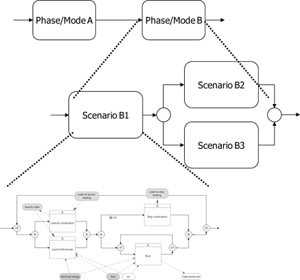
The designer must therefore create an architecture that clearly sets out operations throughout the lifecycle of the system:
– by cooperation between functions exchanging flows;
– structured into scenarios showing how services are provided;
– that are integrated throughout the system lifecycle by consideration of the stages and modes of the system and the transitions between these stages.
Figure 6.1. A functional architecture is a dynamic view integrating the lifecycle of the system
A functional architecture is therefore an abstract view – both structural and dynamic – of “how the system operates”:
– structural: it identifies functions, their organization and their decomposition, and the links between these functions (what data is exchanged? between which functions? etc.);
– dynamic: it describes the “life” of functions (creation, destruction, activation, etc.) and their order of execution (sequential, in parallel, etc.) and data exchanges (protocols implemented).
While this principle of operation should be as independent as possible from technologies (these choices are mostly made during the physical design phase), it should not be independent of the laws of physics and science. Although the functional view is abstract and not linked to any particular discipline, it cannot violate physical principles. The designer should always keep in Antoine Lavoisier’s famous maxim “Rien ne se perd, rien ne se crée, tout se transforme” (nothing is lost, nothing is created, everything is transformed). This is a reformulation of the principle set out by the pre-Socratic philosopher Anaxagoras of Clazomenae, “nothing is born or dies, but existing things combine, then separate once again”.
Functional architecture:
– is not limited to a functional breakdown4. Note, in passing, that this breakdown must obey rules of refinement that ensure the conservation of properties and coherence from one level to the next;
– is not a tree-diagram view presenting a hierarchy of functions.
Figure 6.2. Functional architecture is not a tree diagram
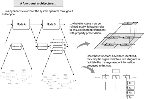
In other words, a function tree does not constitute a functional architecture and is simply a way of organizing functions. This confusion is often a source of errors in perspective and reductive visions of functional design. The main product of functional design activities is thus functional architecture (an engineering view). This architecture may be supplemented by a function tree that organizes and presents the functions identified (an information management view).
6.2.2. Application
6.2.2.1. Mission support
The creation of a scenario in functional design is performed by taking account of functional and non-functional requirements. Functional requirements are used for the quasi-direct identification of functions. The study of non-functional requirements may lead us to identify corresponding technical functions. For example, a technical constraint of resistance to the environment may translate into transformation functions. A constraint of the type “resist external heat” may be translated as functions such as “reflect radiation”, “air condition/heat a space”, “carry out calorie exchanges between a and b”, etc.
For the first scenario Marc and his team must build, they have identified and will give consideration to the following requirements:
– functional requirements:
- the Antarctica Life Support Facility will support the coring missions of the scientific team;
- the Antarctica Life Support Facility will support the pre-analysis of extracted cores;
- the Antarctica Life Support Facility will store the cores extracted by the scientific mission;
- etc.
– functional interface requirements:
- the Antarctica Life Support Facility will allow the exchange of e-mails (with attachments), telephone conversations and video-conferencing, alongside data exchanges, with the OTL laboratory;
- the Antarctica Life Support Facility will allow the exchange of scientific data with the OTL laboratory to support the pre-analysis of cores;
- the Antarctica Life Support Facility will allow conversations and messages to be transmitted between the team carrying out coring activities (outside the base) and the team inside the base;
- etc.
As a first step, Marc collects ideas from his design teams and identifies necessary functions and the flows exchanged between these functions.
Now that the architecture team has obtained this first foundation, they must organize functions dynamically in order to obtain a behavioral model of the expected service. In this case, this organization is relatively simple. These functions are support functions and are therefore “reactive”: they react to external stimuli or orders. There is therefore no real logic requiring implantation for the direction of these functions.
This gives us the functional behavioral model shown in Figure 6.3.
Figure 6.3. “Mission support” functional model
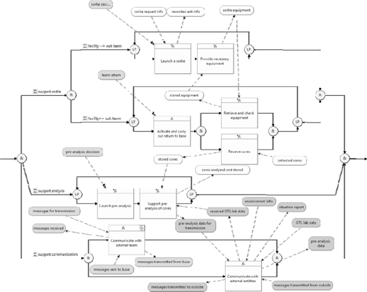
The model here is relatively simple. It is made up of a certain number of repeated activities (loops) that are triggered by external stimuli or orders (triggers) and may be executed simultaneously.
Now that Marc’s team has obtained a functional model, their first reflex, as for any good engineer, is to carry out certain verification activities. In this case, we must verify dynamic behaviors and the reaction of the model to stimuli. This may be achieved by temporal simulation of the model in question.
In its current state, the model is inert as its dynamics depend on external stimuli. To obtain a model that may be simulated from a behavioral point of view, we need to “close” the model using an external behavior (shown in gray in Figure 6.4). This takes the form of a function mimicking an external behavior and thus providing external direction. The functional model for mission support has been abstracted here as an overall function termed “support the scientific mission” to simplify the diagram (see Figure 6.4).
Figure 6.4. “Closed” functional model of “mission support”
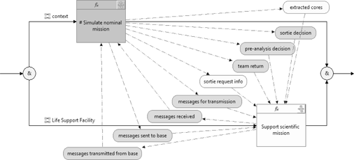
External direction at this stage is “nominal” and present only to stimulate and verify the vivacity of the system and to ensure the validity of its behavioral response (in relation to requirements). Figure 6.5 shows an extract from the “simulate a nominal mission” scenario:
Figure 6.5. Extract from the “carry out coring” scenario

This scenario expresses dynamics, i.e. it “tells a story”, in the following manner:
– the team undertakes an outward journey from the base facility to the coring site;
– once at the site, the team extracts five successive cores (value of the Nb Cores counter), having found an appropriate location for coring;
– the team then returns to the base.
The time taken for these different functions and activities is not always the same, but is represented by probability distributions. This is a result of the fact that in reality things do not always take a fixed amount of time, and so this approximation is entirely reasonable and relevant. It also allows us to play scenarios using non-fixed durations. This last point is particularly relevant when verifying the behavior of functions that are mostly concurrent and asynchronous.
The “mission support” scenario has therefore now been “closed” by an external behavior mimicking a normal mission for the on-site scientific team. We can now move on to simulation.
Here are the results, presented in the form of a filtered chronogram, of a simulation concerning two successive sorties:
– processes linked to cores (Figure 6.6);
– management of equipment (Figure 6.7).
Figure 6.6. Filtered chronogram: processing cores
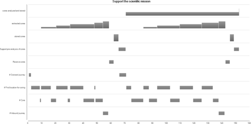
Each sortie results in the extraction of five cores. We note that the time taken for coring and that taken for movement between the base and the site in both directions are not constant. The five cores are stored upon returning to the base; once preanalysis has taken place, the stock corresponds to the total number of extracted cores.
Figure 6.7. Filtered chronogram: equipment management
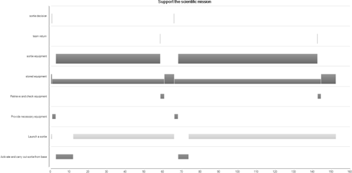
Once again, we observe correct management of equipment (conservation of the total number of items between stored and in-use equipment, correct sequence of functions to process team input/output).
Note, too, that this mission support scenario constitutes a refinement of the operational scenario created by the acquirers. Earlier, Anne formalized the story-board of scientific operations linked to cores to produce an operational scenario using EFFBDs. Here, Marc and his team have added design value, while maintaining compliance with the expectations of the acquirers.
The results, in this case operational scenarios, are therefore valid in relation to the technical requirements and expectations of stakeholders. This compliant refinement is illustrated in Figure 6.8.
Figure 6.8. Functional scenarios in the architecture are refinements of operational scenarios

The context is taken into account here using a nominal model of behavior. Later Marc, with assistance from Michel, may close this model and stimulate the functional architecture using non-nominal behaviors (injection of feared events, inopportune behavior, etc.) by carrying out risk analysis and work on dependability (see section 7.2.1). This will allow him to consolidate the robustness of the architecture from a behavioral point of view.
We also note that the same types of models (in this case a behavioral model) may be used throughout the systems-engineering approach. Each stage of the process has a different viewpoint of the system (black box for defining technical demands, then a “light gray” box, with progressive lightening in order to define an optimal architectural solution), but uses the same system models: functional, dynamical, temporal, behavioral, semantic and physical.
The consistent use of the same formalisms and techniques guarantees improved continuity and efficiency in engineering operations:
– it reduces the validation efforts required to show that the engineering work carried out, transforming input elements into output while adding value to input, is clearly a refinement (in the mathematical sense of the term) and an enrichment maintaining conformity;
– it avoids the “breakages” inherent in certain “diagram-oriented’ representation or modeling techniques. Often, the approaches proposed or illustrated using these techniques associate engineering processes with such diagrams (a use case diagram for the definition of stakeholder needs, a requirement diagram for the definition of technical requirements, activity diagrams, block diagrams for system design, etc.). Each engineering process should, however, operate using a complete and coherent system model (functional + dynamical + semantic +…) in accordance with a given point of view (black box, gray box, white box) and thus use the same techniques and formalisms. Each system model or set of models used in each of these processes is thus of the same nature, but should be a refinement of the model established in the previous process.
6.2.2.2. Life support
For this second scenario that Marc and his team must construct, they once again start from the requirements identified. These include:
– functional requirements:
- the Antarctica Life Support Facility will accommodate the scientific team;
- the Antarctica Life Support Facility will provide food for the scientific team and personnel;
- the Antarctica Life Support Facility will offer laundry facilities for the scientific team and personnel;
- etc.
As before, the first stage of design aims to identify all necessary functions and the flows exchanged.
This leads to the creation of the following scenario, presented here in an intentionally incomplete form (for example, the “electrical energy” flow that departs from the “supply energy” function is distributed to practically all other functions).
Let us go into greater detail concerning one particular technical service: water treatment. Unlike the first example, which highlighted support functions effectively directed from the exterior, in this case operations are autonomous (or finalized) and must be able to auto-direct to attain their objective.
Here, functional design is carried out based on a cybernetic paradigm5: identification of operative and directive functions, i.e. functions that monitor and command operative functions in order to achieve an objective.
Figure 6.10. Functional model for “water treatment”
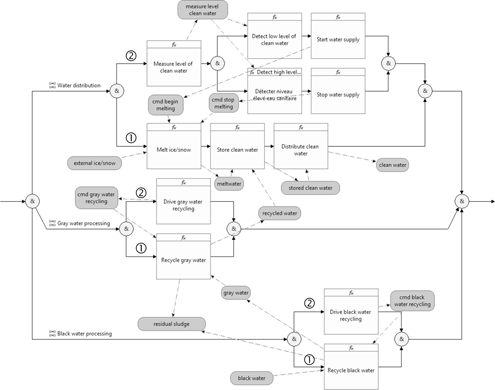
We also note that this is a high-level logical design. We aim to find a global operational logic, rather than provide a detailed description of commands, regulation laws, etc. For example, the model shows commands and their reactions following the detection of a high or low level of clean water (perceptible behavioral dynamic of the system) and not the construction of these levels (fixed threshold, hysteresis, etc.) or algorithms.
Moreover, it clearly shows that functional design is a place to express multidisciplinarity and, although it is an abstract representation, it cannot be created without knowledge of the domains involved. Here, knowledge of the treatment of waste water, split into two main functions, processing gray water and black water, is not “guessed at”, but comes from knowledge of the domain and from experimental work [WRS 04].
This scenario is re-organized following three simultaneous activities: treatment of gray water, treatment of black water and the storage and distribution of clean water. In this case, it is important to identify operative functions ![]() and directive (piloting) functions
and directive (piloting) functions ![]() (control/command, regulation) and the flows exchanged in accordance with knowledge of the domain.
(control/command, regulation) and the flows exchanged in accordance with knowledge of the domain.
The following, more detailed description of these behaviors, involves both detailed knowledge of the domain (biological processes for black water treatment, physio-chemical processes for gray water treatment) and the implementation of design patterns for real-time processing. We shall see an example of implementation in our third example.
Note, however, that the aim of a functional model in systems engineering is not to attain the degree of precision that might be provided by a disciplinary or multi-disciplinary model. These latter models give consideration to biological and physio-chemical processes using systems of differential equations and continuous functions, whereas a functional system model remains resolutely in discrete mode. More generally, as Joël de Rosnay explains [ROS 75], the systemic approach and the analytical approach do not produce models with the same characteristics or the same goals. The analytical approach focuses on details and the nature of interactions and produces models that are useful for the understanding of phenomena. The systemic approach, on the other hand, concentrates on the interactions between elements and the effect of these interactions (not on the nature of these elements and interactions). This is useful in technical decision making (in other words, that which is important for a systems architect).
6.2.2.3. Heating
This third and final example, taken from the functional architecture created by Marc’s team, looks at heating within the facility. It illustrates the following aspects:
– A function is not necessarily the direct translation of a “functional” technical requirement. In this case, operational constraints including “resistance to external climatic conditions”, and requirements in terms of ergonomics and human factors result in this technical function (and other non-functional aspects, such as the thermal isolation capability of the buildings).
– The systems architect, during the design process, makes a certain number of binding technical decisions that must be based on objective choice and trade-off analyses. Here, Marc asked Uwe to carry out a study on the choice of an energy source to produce heat: single or multiple sources, fossil fuels or renewable energy (see section 7.1).
Despite the possibility of choosing a hybrid system using wind and solar energy [GUI 00], Marc and Uwe’s choice falls to the use of fossil fuels (oil, see section 7.1.2.4) as at the Concordia station [FPI 00]. Once this choice has been made, a first functional model is created, in which functions are divided between those that are operative (transformations: burn, exchange, etc.) and those that are directive. In this case, Marc distinguishes between automatic ![]() and manual direction
and manual direction ![]() .
.
This gives the following EFFBD scenario (partial, as certain flows are omitted):
Figure 6.11. Sketch of the functional model for “heating”

As before, this first model does not “work”, and simply allows us to identify functions and flows during this first stage of the process. The addition of behavioral aspects is therefore necessary.
The real (physical) behavior involved here is a continuous behavior. However, the functional models used are discrete models. We must therefore produce an approximation of this function.
This is done by applying appropriate design patterns, allowing us to obtain the dynamic model given in Figure 6.12 that takes account of the two functions “produce heat” and “direct combustion” (functions shown in bold in Figure 6.11). This model thus approaches the real physical behavior.
The continuous operation of the “burn” function is obtained by making the function discrete, with suitable steps and with repetition of the function. Using simulation, we then obtain Figure 6.13. This execution allows us to give consideration to logic of direction ![]() , which starts and stops combustion based on certain conditions. The “burn” function operates by increments
, which starts and stops combustion based on certain conditions. The “burn” function operates by increments ![]() , in a discrete manner, but one that corresponds to real behavior: the quantity of fuel diminishes proportionally with each increment
, in a discrete manner, but one that corresponds to real behavior: the quantity of fuel diminishes proportionally with each increment ![]() , while the quantity of heat produced increases
, while the quantity of heat produced increases ![]() by the same proportions. The measurement/analysis/decision loop allows us to account for the real-time operation of directed combustion.
by the same proportions. The measurement/analysis/decision loop allows us to account for the real-time operation of directed combustion.
This model gives an entirely satisfactory approximation of operations, allowing us to exhibit and comprehend the logic of global dynamic operations. Remember that models, in systems engineering, are not used for analysis or detailed understanding of phenomena (we do not model the continuous physical phenomenon using a system of differential equations), but in order to understand the system as a whole (in this case, its global dynamic behavior).
Figure 6.12. Directed dynamic functional model of the “produce heat” system
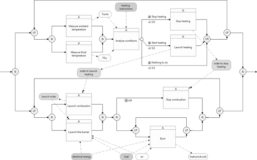
Figure 6.13. Simulation of the “produce heat” system

Upon seeing this model, Roger wonders whether Marc and his teams have gone too far. To Roger, this seems almost useless as, for him, it will lead to the acquisition of an “all inclusive” heating system and it will not be necessary to understand how the system operates. The team should only need to check that the system produces the correct amount of heat and be aware of its production and consumption levels in order to evaluate the quantity of fuel to supply for the mission. Marc admits that this is the lowest level of decomposition he will use, and that it is perhaps already too detailed. On the other hand, he points out to Roger that, based on the identification of these functions, he retains the freedom to allocate them differently and not necessarily all to the same component. More specifically, Marc is considering bringing together all manual direction functions for the station into one central facility supervision entity.
The fact of having produced this functional model with the identification of functions and associated flow monitoring will allow Marc to clearly define the interfaces between this future centralized supervision unit and, among other things, the heating system.
Marc retains a degree of freedom and therefore an additional possibility to optimize the global system. The talent of an architect lies, among other things, in this capacity to avoid closing too many doors at the outset (and, equally, to avoid opening too many doors) in order to obtain the correct “playing field” (see section 6.5) to optimize his system and deal appropriately with the hazards that arise in the course of any project.
6.3. Physical design
Note: in this section, for reasons of simplicity and coherence, the physical design proposed will only consider those functions identified in the previous section (see section 6.2). It will therefore be deliberately incomplete, but coherent.
6.3.1. Identifying physical components
Marc and his team now have the task of identifying, for each “leaf” function on the function tree, a component to “carry” this function, i.e. provide the expected services for this function (transformation, piloting, transportation, storage, etc.).
To do this, they identify a single component that supports this function in cases where this is possible. In other cases, the function cannot be broken down sufficiently, and will therefore be produced by the cooperation of several components, each of which provides a sub-function of the function in question. Functional breakdown should be continued until a level is reached where each “leaf” may be allocated to a single component.
S = 3PI
A system is a set of elements in dynamic interaction organized to achieve a goal [ROS 75]. There is a tendency to think that these constituent or component elements of a system are only tangible and artificial elements. We often forget that the notion of a system is far broader, and covers system typologies such as:
– technological systems, where the majority of component elements are artificial elements based on technologies;
– information and decision systems;
– organizational or socio-technical systems.
In order to achieve their purpose and carry out missions, all these types of systems include not only tangible components, but also humans, as product operators, and procedures, which specify the way to operate products and prescribe means of collaboration between users. The level of integration of these elements is variable.
In fact at certain levels of abstraction or integration, systems may themselves be made up of (sub-)systems.
In summary, we should remember that a system, in a structural (or physical) manner, is an integrated and interacting set of products/people/procedures that together provide the capability to achieve an expressed need or objective.
This definition, which is close to the MIL-STD-499B definition and to that given by Joël de Rosnay [ROS 75], can be summarized in a simple mnemonic: S = 3PI: a System is a set of Products, People and Procedures in Interaction.
A trivial definition of these notions should suffice here:
– Product: coherent and artificial element that may be made up of material, software, data, services, resources, etc.
– Person: a human individual playing a particular role. We shall use the term “operator” to designate these system components in what follows.
– Procedure (or process, or protocol): specification of a series of actions or operations to be carried out to obtain a result, allowing us, among other things, to describe how products should be used by people to carry out system missions.
Note, too, that this vision of the system is valid for design purposes. In earlier processes (requirements and demand engineering) the system is seen as a “black box”, i.e. uniquely through its relationships and interactions with its context. This S = 3PI vision should thus be applied to the overarching suprasystem within which the system in question operates.
Marc and his team must move from a logical vision of the system (how does it work?) to a physical vision (who, or what, does what?). Different methods and techniques are available for use in this process and act as guidelines in their functional breakdown activities and in selecting appropriate components to carry out specific functions (FAST – Function Analysis System Technique – type methods [BYT 07]).
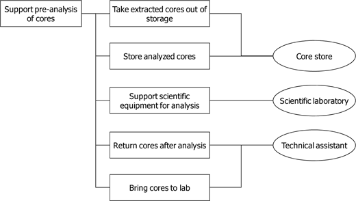
Take, for example, the function “support pre-analysis of cores”. The design team is well aware that they have not gone far enough in their breakdown, and that this function will involve both products and people, working following a process.
This may all be formally described by a scenario, but in this case we shall simply give the functions identified during this breakdown.
This gives us a FAST diagram (see Figure 6.18).
Figure 6.14. FAST diagram of the “support pre-analysis of cores” function
Marc and his team repeat this process for all functions, breaking down those that require such treatment then identifying the component which executes the function.
6.3.2. Allocation of functions to identified components
A few “simplifying” hypotheses:
– the different components fulfilling functions linked to communications (which we have not broken down any further before now) will be grouped together into a “communications” sub-system. Thus, as a shortcut and simplification, all communications functions will be directly allocated to this sub-system, without identifying more specific components;
– in the same way, the “HyperDrill support” mission has not been the object of functional design here. We shall also take a shortcut by introducing a “HyperDrill support” sub-system.
At the end of this process, the architecture team lead by Marc has identified the (partial) set of components presented in Table 6.1.
Table 6.1. Allocation of functions to identified components
| Component … | … Performs functions |
|---|---|
| Bathroom | Provide hygiene facilities |
| Bedrooms | Provide sleeping facilities |
| Black water recycling unit | Drive black water recycling Recycle black water |
| Boiler | Measure fluid temperature Launch combustion Launch the burner Stop combustion Burn Drive circulation of heating fluid Exchange heat |
| Clean water tank | Store clean water Measure level of clean water Melt ice/snow |
| Communication S/S | Communicate with external team Send message to external team Receive message from external team Communicate with external entities |
| Cook (operator role) | Prepare meals Wash dishes |
| Core store | Store cores Remove cores from storage Store analyzed cores |
| Dining area | Take meals |
| Take meals | Produce electricity |
| Electrical network | Distribute electricity |
| Equipment supervisor (operator role) | Check state of outgoing equipment Issue equipment to team Take equipment from team Check state of incoming equipment Send equipment for repair |
| Exit lock | Activate and carry out sortie from base Activate and carry out return to base |
| Facility supervision unit | Detect low level of clean water Start water supply Stop water supply Detect high level of clean water Measure ambient temperature |
| Facility supervision unit | Analyze conditions Stop heating Launch heating Program ambient temperature Regulate temperature of heating circuit |
| Fuel tank | Store fuel oil |
| Store fuel oil | Process waste |
| Gas tank | Store gas |
| Gray water recycling unit | Drive gray water recycling Recycle gray water |
| Heating fluid distribution network | Distribute fluid |
| Kitchen | Cook food Provide washing dishes facilities Store kitchen utensils |
| Launderer (operator role) | Sort dirty laundry Launch washing Hang out laundry |
| Laundry | Wash laundry Dry laundry |
| LogBook | Record sortie Record pre-analysis activity |
| Radiators | Diffuse heat |
| Recreation area | Support leisure activities |
| Refrigerated store | Store perishable goods |
| Scientific laboratory | Support scientific equipment for analysis |
| Sport facility | Support sports activities |
| Store | Remove equipment from storage Store equipments Store various products |
| Technical Assistant (operator role) | Unload cores Transport cores to lab Return cores after analysis |
| Toilets | Provide toilet facilities |
| Water distribution network | Distribute clean water |
| Workshop | Receive damaged equipment |
The choice, in the strictest sense, of components is carried out using nonfunctional characteristics (the product of non-functional technical requirements):
– directly accounting for characteristics (performance engineering, dependability engineering, etc.);
– immediately eliminating options or components that do not conform or do not sufficiently fulfill these characteristics;
– potentially selecting a candidate component, of which the applications cover expectations;
– using these characteristics to compare potential solutions (choice criteria);
– using these characteristics as a variable to optimize a solution.
We may note the importance of characterizing functions by associated performances (capacity, frequency of use, production, etc.).
6.3.3. Grouping components by sub-system
The components identified in this way should now be grouped into a limited number of sub-systems (ideally around seven6). Grouping is carried out by applying a certain number of heuristics in order to produce the desired properties in the proposed final architecture (for example minimization of interfaces between sub-systems).
Note, too, that the identified sub-systems are, in fact, systems at their own level. A sub-system-based architecture is not, therefore, a “technical” or “geographic” architecture or a product deployment architecture. A sub-system represents a coherent, operational and abstract unit and not a geographic, geometric or “anatomical” dissection of the system. This difference may be illustrated by analogy with the human body. A systems vision of the human body would break the body down into sub-systems, such as the cardiovascular system, nervous system, lymphatic system etc., which constitute “components” operating throughout the body. Each of these sub-systems has a purpose and carries out one or more missions. A “geometric” (or, in this case, anatomical) vision of the human body would break the body down into a torso, arms, legs and a head.
A physical architecture structures the system as a set of sub-systems, which may themselves be broken down further into “sub-sub-systems” and so on. This tree-diagram vision of the system, with successive decompositions into blocks, produces a SBS (system breakdown structure, see section 5.2.3). The technical (or disciplinary) vision of the system that results from the passage or projection onto technologies will give us the BoM (bill of materials, see section 5.2.3) and models for the deployment, assembly, etc. of these products.
The systems architect therefore needs to juggle across three levels: a functional level, a physical level and a technical (or technological) level. He must ensure coherence between these three levels and the projection of the functional level onto the physical level and the physical level onto the technical level. Models referred to as “system” models are functional and physical models.
Figure 6.15. Difference between the systems architecture and technical architecture viewpoints

For example, in the case of Concordia [GOD 00a], the technical architecture took the form of two buildings built on self-lifting bases. Each building took the form of a vertical cylinder (made up, in fact, of 18 flat faces) with three floors and supported by six bases or “feet”. These bases rest on the ice sheet over a large surface in order to distribute the weight and move vertically using a hydraulic system to keep the building horizontal in spite of snow build-up or ice movements.
These two buildings constitute two zones: one “quiet” zone, for rest and laboratories, the other “noisy” zone for meals, sport, leisure and workshop activities.
Marc’s team has identified six sub-systems for the Antarctica Life Support Facility. In addition to the “communications” and “HyperForeuse support” subsystems, they identified the following:
– “life support” sub-system;
– “comfort” sub-system;
– “technical support” sub-system;
– “base supervision” sub-system.
They then arrange the components identified previously as shown in Table 6.2.
Table 6.2. Components grouped by sub-system
| Component … | gathered in the S/S … |
|---|---|
| Bedrooms Launderer Recreation area Bathroom Dining area Sport facility Laundry |
Comfort S/S |
| LogBook Operational supervisor Facility supervision unit |
Facility Supervision S/S |
| Gray water recycling unit Black water recycling unit Toilets Water distribution network Heating fluid distribution network Radiators Refrigerated store Clean water tank Cook Kitchen Boiler |
Life Support S/S |
| Technical Assistant Workshop Fuel tank Gas tank Electrical generator Scientific laboratory Store Core store Garbage container Equipment supervisor Exit lock Electrical network |
Technical Support S/S |
6.3.4. Architecture of (some) sub-systems
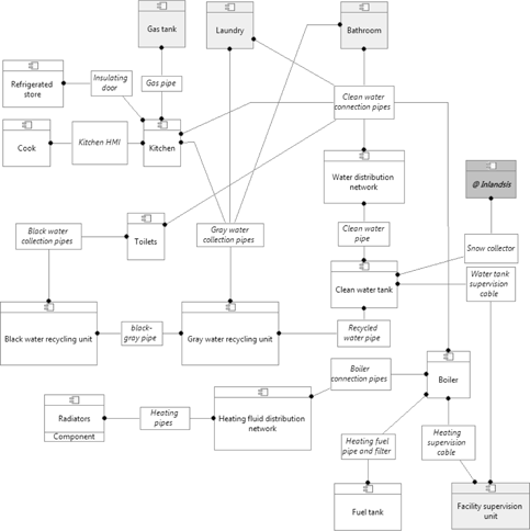
The physical architecture of sub-systems shows the components that make up this sub-system and the set of links between these components and with other components outside of the sub-system under consideration.
We will show a partial and simplified version of the work carried out by the architecture team on three of the sub-systems identified.
These sub-systems may be considered as systems in their own right, and so we shall describe them (briefly) here using the main characteristics of a system introduced in section 4.1 (“what system are we dealing with?”):
– purpose;
– missions;
– context: in this case, this will be described using a physical architecture showing other sub-systems – marked in light gray – and external components – marked in medium gray with italic text and preceded by “@” – with which the sub-system in question is linked.
6.3.4.1. “Life support” sub-system
The purpose of the “life support” sub-system is to support human life for the duration of the operational mission in Antarctic conditions for the scientists and personnel of the facility.
The missions of the “life support” sub-system are to:
– provide sustenance and a water supply for human individuals;
– permit personal hygiene activities;
– maintain a reasonable temperature and comfortable conditions in the Antarctica Life Support Facility.
Figure 6.16. Physical architecture of the components of the “life support” sub-system
6.3.4.2. “Technical support” sub-system
The purpose of the “Technical Support” sub-system is to provide the necessary technical services for the operations of the Antarctica Life Support Facility.
The missions of the “Technical Support” sub-system are to:
– supply electrical energy to the equipment of the Antarctica Life Support Facility;
– supply, store and distribute consumables (fuel, gas, food, waste treatment);
– store and maintain necessary equipment for expeditions; and
– support the operation of scientific equipment.
Figure 6.17. Physical architecture of the components of the “technical support” sub-system

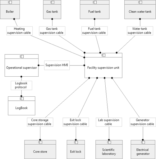
6.3.4.3. “Base supervision” sub-system
The purpose of the “base supervision” sub-system is to guarantee the continuity of mission services for the Antarctica Life Support Facility.
The missions of the “base supervision” sub-system are:
– operational and technical surveillance of the components of the Antarctica Life Support Facility; and
– configuration and direction of components of the Antarctica Life Support Facility.
Figure 6.18. Physical architecture of the components of the “base supervision” sub-system
6.3.5. Sub-systems architecture of the life support facility
By assembling the three sub-systems described above, we obtain the physical architecture of the Antarctica Life Support Facility shown in Figure 6.19.
This architecture is incomplete as only three of the sub-systems have been studied at component level.
Figure 6.19. Physical architecture, in sub-systems, of the Antarctica Life Support Facility

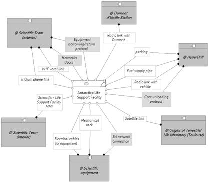
The set of links between the various sub-systems is clearly incomplete at this stage. However, the process of designing the life support facility system (with the passage from a black box view to a white, or “light gray”, box view) has revealed new links between the base and its context.
Certain links (and, consequently, interfaces) had previously been forgotten. This is understandable: working with a black box vision can, at times, be relatively limiting.
Other links are introduced by the chosen solution and are therefore a product of system design.
In any case, we need to update the context models of the system under consideration. For example, additions are made to the physical viewpoint in the following manner (new links are shown in gray):
Figure 6.20. Physical architecture of the context of the Antarctica Life Support Facility in its operational context
6.4. Interfaces
The mastery of interfaces is always a key point in mastering the architecture of a system. Marc, a veteran in the field of systems architecture, is well aware of this.
The mastery of the functional and physical architectures and the coherence of these different plans (components execute functions identified by the functional design, and the physical architecture is a “projection” of the functional architecture) are all indispensable elements in interface engineering. It allows these processes to be carried out based on very solid foundations. However, these elements are not sufficient.
From functional to physical: some elements for interface determination
An interface between two components is:
– the set of physical links between components (physical interfaces);
– the set of flows transported by these links (functional interfaces);
– the distribution of flows over links (who, or what, transports what?);
– all technical elements involved, both from a functional (transmitting a flow from one component to another involves, at the very least, sending, transportation and reception) and physical (link and connection characteristics, etc.) viewpoint.
What, then, should our starting point be for the identification of links between components and the determination of interfaces between these components?
– the projection of the functional architecture onto the physical architecture (each specific function is executed by a component);
– couplings between functions in the functional architecture. These are of two kinds:
- flows: that which is produced by functions is consumed by other functions,
- control structures: the dynamic sequence of functions;
– identified links between components.
Determination of functional interfaces
We might think that the functional interfaces of a component could be deduced from the allocation of functions. However, this statement requires qualification, giving suitable consideration to the following remarks:
– several functions may potentially produce the same flow;
– a flow produced by a local function in a component and consumed by another local function in the same component may also be consumed (selectively or otherwise, depending on the nature of the flow, material/energy or information) by a function of another component;
– a local function in a component could consume a flow produced by two other differently allocated functions: One local function of the same component and one of a different component (multiple or alternative supply source);
– etc.
We would be tempted to affirm that, formally:
– {input flow of component} ⊆ ∪ {input flow of functions allocated to this component}; and respectively
– {output flow of component} ⊆ ∪ {output flow of functions allocated to this component}.
This is only valid if the identification of function flows is complete.
A quasi-automatic deduction of functional interfaces based on the information provided by functional models and the allocation of functions to components would often, therefore, give a restrictive vision. Although this provides us with a certain and valuable starting point, we should be wary of overly hasty conclusions and not attempt to avoid necessary engineering activities.
Allocation of flows (and flow monitoring)
Another idea – also overly naïve – would be to believe that the information concerning the allocation of functions to components allows us to deduce potential links between these components and the flows transported by these links.
Take the example of two sequential functions, of which the first F1 produces a flow a, which is consumed by the second function F2. These two functions, F1 and F2, are allocated to two components, C1 and C2, respectively. Using a naïve approach to interface engineering, we would say that a link exists between C1 and C2 transporting flow a.
This vision is perfectly plausible and relevant in a large number of cases. It cannot, however, be considered to be unique or definitive. In reality, the coupling between F1 and F2 (both the coupling in terms of flows exchanged and in terms of flow monitoring) may consist of:
– the identification of an intermediary component, C3, to relay the flow (examples of this are widespread: telecommunications networks relaying electromagnetic signals, email servers, pumps activating circulation in a hydraulic network, etc.);
– the identification of a component C4 that ensures the direction of the sequence between these two functions in the case where the functions are not “naturally” sequential, or where this direction is not provided by one of the components (master/slave relationship, client/server, etc.).
The following diagram shows a more elaborate version of the physical architecture resulting from the same starting point in terms of functional architecture and the same allocation of functions to components.
From this diagram, we may deduce that:
– if a function allocated to a component exchanges a flow with another function allocated to another component, then there must be a “route”7 between these two components allowing the transmission of the flow in question;
– if a function allocated to a component is coupled in terms of flow control with another function allocated to another component, then there may be another component (or several components) in charge of directing and ensuring the sequentiality of these functions.
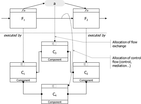
In conclusion, we should remember that interfaces cannot be mastered without prior mastery of the functional architecture and the allocation (projection) of this architecture onto physical architecture. The identification and definition of interfaces do not happen automatically based on these elements, but they are a necessary condition for these activities. Remember, too, that – as in all engineering activities – the architect must provide objective and reasoned added value in terms of interface design.
These efforts in terms of interface engineering on the part of Marc and his team permit the determination of consistent interfaces, both by the passage from a functional to a physical architecture (projection of the former onto the latter) and by enrichments. Let us, then, look more closely at their activities in relation to a representative sub-group, that of “technical support” (see section 6.3.3.2).
This partial example allows us to show a number of particular enrichments resulting from the work of the architecture team and that result in a less trivial determination of interfaces than that produced by simple deduction based on the allocation of functions to components.
We shall now present the work carried out by Marc and his team in more detail.
6.4.1. Waste management
The analysis of the recommendations made by the SCAR (Scientific Committee on Antarctic Research) [SCA 08] and the Antarctic Treaty System [ATS 59] concerning waste management and implementation by the French Polar Institute stations (the Institut Polaire Français Paul-Emile Victor) [GOD 02], may be summarized as follows:
– reduce the quantity of waste for processing by as much as possible;
– train expedition members in these practices;
– establish simple procedures for waste processing that respect the environment, in accordance with the recommendations cited above.
Two of these procedures are of particular interest to us:
– all residual sludge from the water treatment process is stored then repatriated;
– the bulk of waste produced should not be incinerated, but ideally stored before being repatriated.
The functional architecture (scenarios linked to life support, section 6.2.2.2) identified a residual sludge flow as an output of water recycling functions, but this flow led nowhere. In this case, the added value lies in the identification of a physical link between recycling units and the garbage container used to store residual sludge ![]() by applying the recommendations cited above. In order to complete his work on this aspect, Marc considers associated physical dimensions: the mass and volume of waste and its contribution to the mass and volume of flows repatriated from the Life Support Facility to Dumont d’Urville.
by applying the recommendations cited above. In order to complete his work on this aspect, Marc considers associated physical dimensions: the mass and volume of waste and its contribution to the mass and volume of flows repatriated from the Life Support Facility to Dumont d’Urville.
Figure 6.21. Functional → physical: waste management

In the same way, a protocol-based interface can be planned involving the kitchens and the scientific team (and certainly other entities not yet identified in this partial architecture) in waste management ![]() .
.
6.4.2. Centralized supervision
One of the design decisions taken by Marc concerns the establishment of centralized supervision of the Antarctica Life Support Facility using a component identified as the “facility supervision unit”. Once this choice is made, the physical design highlights links between this unit and the different components it supervises. It also introduces a number of new engineering elements, including surveillance and observation functions, and additional information and command flows.
Figure 6.22 shows certain physical links between this centralized supervision unit and the components it supervises.
Figure 6.22. Examples of links (and therefore of interfaces) created by the centralized supervision unit

We clearly see here that certain engineering elements, such as functions and flows – and therefore links and components – are not the direct product of input technical requirements, but a value added by the design team through trade-offs, choice studies and decisions. This leads to “derived” requirements, i.e. requirements resulting from design choices rather than from an initial need.
6.4.3. Other types of interactions between components
Certain links between components do not transmit interactions resulting from functional design (and do not, therefore, transport functional flows). These links typically connect or isolate components from a mechanical, thermal, etc. point of view.
The implementation of scientific equipment (entities external to the system) in the Antarctica Life Support Facility system will involve physical links carrying flows (links for the power supply, computer communications, etc.) and links allowing coupling of this equipment with the facility. The architecture team therefore identifies a rack-type mechanical interface with this equipment.
Figure 6.23. Example of mechanical coupling between two components

6.5. The “playing fields” of the systems architect
First, we should remember that system design is based upon two points of view:
– the functional point of view, where the architect essentially handles functions, the flows between these functions, control/monitoring structures (sequencing) and the breakdown of these functions into dynamic scenarios;
– the physical point of view, where the architect mostly handles components and links and the breakdown (or re-assembly) of these components.
These two points of view must be perfectly coherent, as one (the functional viewpoint) is projected onto the other (the physical viewpoint). This projection of one onto the other means that:
– the components of the physical architecture carry out the functions of the functional architecture;
– the links present in the physical architecture transport flows from the functional architecture.
This is, of course, a simplified and reduced vision, as seen in previous chapters. Figure 6.24 summarizes the progression and the projection of specific functions onto components (showing a partial aspect of design).
Figure 6.24. Different playing fields (opportunities for choice) of the systems architect

This shows that the process of constructing an architecture is iterative and incremental, where the systems architect has three possible fields of play.
1) Functional breakdown: playing field 1
The architect has a degree of flexibility in the way in which he breaks down the expected services from his point of view as a designer, and may thus introduce design choices. He may “play” with:
– variants in the production of services or macro-functions;
– technological choices (for example, user recognition technologies in one of the examples introduced in the boxed portion of section 6.1) that introduce specific subfunctions: for example voice recognition, password checks, etc.;
– the application of standard or capitalized design patterns within this environment;
– etc.
2) Component choice: playing field 2
Here, choice is often directed by the reasoned application of a doctrine: make, buy or re-use. Other aspects that assist the architect in the choice of the best components include:
– the constraints expressed and formalized by various stakeholders, which reduce the field of choice (imposed technologies, re-use of off-the-shelf components, consideration of pre-existing elements, import/export constraints);
– application of decision models or optimization techniques (mono- or multiobjective, concerning one or more disciplines);
– etc.
3) Projection of functions (and performances) onto components: playing field 3
Here, the architect must make use of a certain number of criteria or heuristics to group functions for execution by the same components, or conversely to separate or segregate them using different components. The following (non-exhaustive) list provides a few potential criteria or heuristics that may be used:
– grouping or separation by analysis of flows exchanged between functions (for example to minimize the number of interfaces between components);
– grouping or separation by levels of temporal invariance (coherence in relation to the temporal hierarchy of the system);
– grouping by functional category: operative functions, observation and surveillance functions, piloting/driving functions, decision functions, etc.;
– grouping or separation by performance criteria;
– grouping or separation using criteria linked to a skills map or a programmatic environment;
– etc.
In short, the challenge facing the architect is to obtain expected emergent characteristics and to minimize negative emergent characteristics, all the while guaranteeing a certain number of significant (and desired) architectural properties:
– modularity;
– evolutiveness;
– interoperability;
– scalability;
– etc.
These properties are potentially contradictory and may enter into conflict.
The systems architect must therefore consciously and voluntarily adopt a strategy based on the major significant properties to be obtained. This strategy will affect the way he or she “plays” with the possibilities offered in different areas of systems design according to the degree of freedom permitted.
6.6. EFFBDs
6.6.1. An informal introduction to EFFBD diagrams
When seeking to represent the functional structure of a system and data exchange flows in an efficient and effective manner, a systems engineer will often use relatively simple graphical descriptions.
Some of the most common types of representations of this kind include FFBDs (functional flow block diagrams), developed towards the end of the 1950s, and their derivatives, EFFBDs (enhanced FFBDs) [LON 95]. These allow simple modeling of the behavior of complex, distributed, hierarchical, concurrent and communicating systems.
More specifically, EFFBDs describe the functions produced by the system and the order in which they must be executed.
This order is specified using three types of elements:
– the dynamics of functions, i.e. their duration of execution;
– the control/monitoring flow, i.e. control structures;
– the data flow, split into items and resources.
The language includes the usual control structures, such as:
– parallel branches (represented by the symbol ‘&’); moreover, each branch may force the termination of other branches if it carries the ‘kill’ marker;
– “exclusive or” choice structures (symbol: ‘OR’) and multi-exit functions;
– iterations (‘IT’) and loops (‘LP’).
Moreover, control structures may be nested. Figure 6.25, based on [LON 95], presents an example of an EFFBD showing the possibilities of the language.
Figure 6.25. Example of an EFFBD based on [LON 95]

The behavioral semantics of EFFBDs are relatively intuitive, and consist of a set of rules for evolution describing the movement of the control flow through the model, the execution of functions, the production and consumption of data, etc. Thus, a parallel structure behaves as follows:
– when the control flow arrives at the entrance of the structure, it activates the first structure of each parallel branch;
– once the last structure of each parallel branch has finished its execution, the control flow leaves the parallel structure and activates the next structure.
Note that this behavior may produce states of final synchronization between branches.
The behavior of a function, once activated by the control flow, is considerably more complex. It may be described by the following algorithm:
1) (if necessary) wait for all input flows to become available;
2) (if necessary) consume all input flows in a synchronous manner;
3) begin execution;
4) after a certain period, defined by the parameters of the function:
5) terminate execution;
6) (if necessary) produce all output flows in a synchronous manner;
7) transfer the control flow to the following structure.
6.6.2. Syntax and structure of EFFBDs
An EFFBD diagram is therefore a set of:
– functions (a transformation of form, time or space applied to information, energy or materials) with a certain execution time (fixed, distribution, etc.);
– control structures;
– flows (items or resources).
An EFFBD represents a scenario, and is thus a behavioral view of the system.
6.6.3. Formalization of EFFBDs
In order to carry out the verification and validation activities described in the following section, we require a formalization of the syntax and semantics of EFFBDs, allowing us to acquire a non-ambiguous representation of the behavior of the model.
Thus, in a formal manner, an EFFBD may be seen as a set of:
– nodes modeling control structures and functions; depending on its nature, each node may have predecessors or successors;
– flows of data linked to functional nodes by weighted arcs, marking the quantity of flows exchanged;
– intervals8 that give minimum and maximum execution times for each function.
The behavior of an EFFBD is then described as an ordered series of states. Each state represents:
– the activity of each node: a node may be inactive, activated, executed (in the case where it is waiting for synchronization in a parallel branch) or, for functions, in execution;
– the level of each flow, i.e. the quantity of flow available in this state;
– the time that has passed since the start of execution of each function.
The passage of time here is a continuous process: each model therefore has an infinite number of possible executions. The set of these executions may be represented symbolically by a timed transition system, or TTS, as introduced in [HEN 91]. Formally, the semantics of an EFFBD is a quadruplet (S, s0, N, →) where:
– S is the set of states;
– s0 is the initial state;
– N is the set of nodes in the model;
– → is the transition relationship that formalizes the semantic rules introduced above.
The relationship → consists of:
– a discrete transition relationship, which models the passage from one control structure to the other;
– a continuous transition relationship, representing the passage of time.
As an illustration, let us suppose that the model is in a state s and that we wish to enter into a parallel structure of which the opening node is denoted a. In this case, the relationship → describes the passage from state s to the following state s' in the following manner:
– [precondition] the activity of a in state s is activated;
– [post-conditions] the activity of a in s' is inactive, that of the successors of a that represented the first structure of each parallel branch, is activated and that of the other nodes remains unchanged.
Let us now suppose that the model is in a new state s and that we wish to escape from a parallel structure (the node closing this structure is denoted a). In this case, the relationship → describes the rule for synchronization between parallel branches of the structure, as mentioned above:
– [precondition] the activity of a in state s is activated and the activity of all of its predecessors is executed;
– [post-conditions] the activity of a and of its predecessors in s' is inactive, that of the successor of a is activated and that of the other nodes remains unchanged.
The complete semantics of EFFBDs, including a description of the continuous transition relationship (which we shall not go into here), are presented in [SEI 09].
6.6.4. Verification and validation of EFFBDs
Verification actions are essential in mastering major characteristics of a system, such as dependability characteristics, and as such they form an integral part of systems engineering processes [IEE 05]. While it is common (and relatively simple) to carry out simulations to check the behavior of a behavioral model, this method of testing cannot, on its own, guarantee the correct operation of the system. Even for systems of a “reasonable” size, this type of analysis cannot be exhaustive and cover all possible cases, and we run the risk of not noticing situations that are potentially dangerous for the system or its environment.
In order to overcome this issue, we may use formal methods such as modelchecking. The principle of this approach consists of defining a formal model of the system, Σ, and a formal model of the behavioral property to be verified, Φ, and implementing suitable algorithms and data structures to determine whether Σ verifies Φ, which is denoted “Σ╞ Φ”.
The drawback in the use of this kind of approach is that effective and powerful algorithms used to carry out the proof Σ╞Φ operate using “low level” formal models of the system and mathematical behavioral properties. These models are not always easily accessible or appropriate for use in systems engineering. We therefore aim to conserve a “high level” expression of the system and its properties and transform them into “low level” equivalent formal expressions. Σ is transformed into its equivalent σ and Φ becomes φ. Verification of “Σ╞ Φ?” is therefore transformed into the verification of “σ╞ φ?” as shown in Figure 6.26.
In the case of EFFBDs, the corresponding “low level” model is based on temporal Petri networks. Verification is then carried out on these equivalents using a specialized model checker, ROMEO. The results of analyses are then retranslated to high-level models in order to facilitate reading. The interest of this approach, at several levels of abstraction, is that it allows us to profit from the power of model checking in Petri networks, without needing to develop a specific model checker for EFFBDs, and that we can “hide” the complexity of the formal method from the systems engineer, making his analysis more effective and relevant [SEI 09].
The formal model of EFFBDs was mentioned in section 6.6.3; moreover, a certain number of formal logics exist that allow us to express more or less complex behavioral properties.
Thus, timed computation tree logic, introduced in [ALU 93], is sufficiently expressive for use in describing complex quantitative temporal properties, such as “reception of the Alarm flow always triggers the Fall back function in less than 5 ms”.
Figure 6.26. Model checking and transformation of models

Nevertheless, it remains tricky to use effectively and it is generally more useful to define a limited set of property classes corresponding to needs and “trade” practices using natural language.
Table 6.3 gives an idea of some verifiable property classes.
Thus, a Class I property allows the detection of a deadlock in the system, for example a situation where a function is waiting for a flow that will never be produced. Class III allows us to test the non-concurrence of several functions, and class IV allows us to detect cases where a time delay is exceeded. Finally, class V shows the upper boundary of a flow. This property is particularly useful in dimensioning the system, and especially the size of queues in data flows. Moreover, the presence of an unbounded element in the model should alert the designer to a modeling error: most systems we encounter are physically and intrinsically bounded.
Table 6.3. Property classes

6.7. Things to remember: architectural design
Marc and his team have carried out system design, creating a functional architecture and a physical architecture and carrying out all other activities necessary to the execution of this construction in a complete, coherent and objective manner (Architectural Design in [ISO 08a]). As we have already stated a number of times, as all technical engineering activities, this is an this is an activity of (i) transformation (ii) based on reasoning (ii) producing added value:
(i) transformation: from a set of requirements (prescriptive vision of the system) to an architectural solution, completely accounting for all functional aspects and globally optimizing non-functional aspects;
(ii) based on reasoning:
- through an incremental and iterative approach that responds to a series of questions: How does the system function? How does the system act? (On what? By whom? Where? When? etc.),
- which adopts an internal viewpoint at the correct level of breakdown, both in terms of depth and in breadth, while continuing to consider the system in different contexts throughout its lifecycle,
- which considers the solution from at least two complementary and coherent points of view of the system: a functional architecture view and a physical architecture view,
- which provides mutual enrichment of these two viewpoints by projecting/allocating the functional architecture and by projecting/distributing nonfunctional characteristics onto the physical architecture (performance models and budgets);
(iii) producing added value:
- the application of heuristics, design patterns and feedback allows us to create robust architectural solutions that respond to constraints,
- the holistic approach tends towards the search for a global optimum, and thus the best compromise, to the detriment of local optima,
- the application and direction of appropriate system studies is used to promote emergent behaviors expected of the system, while avoiding negative emergences or immersed behaviors,
- technical choices and decisions taken in a relevant causal order allow us to converge on a solution (this point will be dealt with in more detail in section 7.1).
Systems architecture is both an art (application of heuristics and feedback) and a science (analysis and the consideration of certain characteristics are based on scientific techniques: dependability, mechanics, thermal science, etc.). A talented systems architecture team is able to maintain the delicate balance between creativity or imagination and logical reasoning.
6.8. Bibliography
[ALU 93] ALUR R., COURCOUBETIS C.A., DILL D.L., “Model-checking in dense real-time”, Information and Computation, vol. 104, pp. 2–34, 1993.
[AMB 00] AMBLARD P., LASESERRE J.-C., PERSONNE J.-C., Core Water Recycling Life Test, Final Report (contract n° 13684/99/NL/MV) Techno Membranes, University of Montpellier, September 2000.
[ATS 59] ATS, Antarctic Treaty System, www.ats.aq/e/ats_treaty.htm), December 1959.
[BYT 07] BYTHEWAY C., Fast Creativity and Innovation: Rapidly Improving Processes, Product Development and Solving Complex Problems, J. Ross Publishing, London, 2007.
[FPI 00] FPI (French Polar Institute), Concordia, A New Permanent, International Research Support Facility High on the Antarctic Ice Cap – Technical Overview, 2000.
[GOD 00a] GODON P., CUCINOTTA N., “Concordia: a new permanent, international research support facility high on the Antarctic ice cap”, Proceedings of the 6th International Symposium on Cold Region Development, Hobart, Tasmania, pp. 72-75, January 31-February 4, 2000.
[GOD 02] GODON P., “Programme de Gestion des Déchets des Stations Antarctique”, IPEV, Département de la Logistique Polaire, 1994, 2002.
[GUI 00] GUICHARD A., MAGILL P., PATERSON C., WILLIAMS G., “Energy services: back to basics and up to hybrids”, 9th SCALOP Symposium, Tokyo, 2000.
[HEN 91] HENZINGER T.A., MANNA Z., PNUELI A., “Timed transition systems. Real-time: theory in practice”, Proceedings of the REX Workshop, Computer Science, vol. 600, pp. 226–251, Springer, New York, June 1991.
[IEE 05] IEEE Standard for Application and Management of the Systems Engineering Process, IEEE 1220, IEEE, 2005.
[ISO 08a] ISO, Systems Engineering – System Life Cycle processes, ISO/IEC 15288, ISO, 2008.
[KLO 09] KLOTZ O., WIPPLER J.-L., “Ne dites pas à ma mère que je fais de l’architecture système, elle croit que j’alloue des exigences…”, 4e Journée Thématique AFIS, Architecture de Systèmes et Lignes de Produits, Toulouse, February 2009.
[LON 95] LONG J., “Relationships between common graphical representations in systems engineering”, 5th International Symposium of the INCOSE, INCOSE, Saint-Louis, USA, July 1995.
[MIL 56] MILLER G.A., “The magical number seven, plus or minus two: some limits on our capacity for processing information”, Psychological Review, n° 63, pp. 81-97, 1956.
[ROS 75] DE ROSNAY J., Le Macroscope, Points, Paris, 1975.
[SCA 08] Scientific Committee on Antarctic Research, www.scar.org, 2008.
[SEI 09] SEIDNER C., Vérification des eFFBDs: Model-checking en Ingénierie Système, Doctoral thesis, University of Nantes, 2009.
[THO 92] THOMÉ B., System Engineering: Principles and Practice of Computer-based System Engineering, Wiley, London, 1992.
[WRS 04] WRS (Water Recycling Systems for the Antarctic Concordia Station) Aurora Program (www.esa.int/SPECIALS/Aurora/) and Advanced Life Support (ecls.esa.int/ ecls/?p=waterrecycling), 2004.
1 Chapter written by Charlotte SEIDNER and Jean-Luc WIPPLER.
1 See following note.
2 Depending on the standard or work, the terms “logical” and “physical” (in relation to design and architectures) may be used in the place of “functional” and “organic”, respectively. The term “physical” is generally preferred to “organic”, which has specific links to the domains of biology and chemistry. The terms “functional” and “physical” will be used in this work (but should not be confused with “technical” – see section 6.3.2).
3 The name “Verdi” does not refer to any existing project in this case, and is simply inspired by the famous Italian composer Giuseppe Verdi (1813–1901). All similarity to an existing or historical project is purely fortuitous and unintentional.
4 A functional decomposition may be obtained simply by using a mathematical composition operator: g ![]() f (x) = g( f (x)), but this rarely produces a “good” representation, or by using formal systems, such as lambda-calculus, pi-calculus or combinatory logic. We would do better to talk of “refinement” rather than decomposition.
f (x) = g( f (x)), but this rarely produces a “good” representation, or by using formal systems, such as lambda-calculus, pi-calculus or combinatory logic. We would do better to talk of “refinement” rather than decomposition.
5 Plato used kubernêtikê (Greek, Κυβερνητική) to designate the piloting of a ship, and used it as a metaphor to express the art of good governance. The French cybernetics pioneer Louis Couffignal defined it as “the art of rendering actions efficient”.
6 This constitutes a cognitive limit in the human capacity to process concepts and ideas simultaneously [MIL 56] and should therefore constitute a reasonable limit for an architecture team in order to guarantee mastery.
7 If we consider a graph where the vertices (or nodes) are components and the arcs represent links, this boils down to stating that there is an elementary and simple path between the two components, of which each arc (link) transports the flow in question and each vertex (component) does not alter, but simply relays, the flow.
8 Other (mathematical) functions may be used to describe execution times, such as Gaussian distributions, but these are not discussed here.

