Chapter 4
Finding the Right Problem 1
“A problem without a solution is a badly posed problem.
“One day, machines will be able to answer all questions, but they will never be able to ask one!”
Albert EINSTEIN
“I keep six honest serving-men (they taught me all I knew). Their names are What and Why and When and How and Where and Who.”
Rudyard KIPLING
As in any reasoned approach, one of the first steps in systems engineering consists of establishing a problem and expressing the purpose of the system in the form of a series of expectations or constraints. In this case, the expression of the problem will involve, among other things, the creation of a specification. This capturing and formalization of needs is essential as the quality of a service or product is measured by its ability to satisfy the expectations of the users of the system, expressed or otherwise.
Architectural design activities, which we will consider later, allow us to find the optimal solution and therefore the “right” architecture, including constituent elements, the way in which these elements are laid out and, especially, the network of interactions between these elements, so “an organized set of elements in dynamic interaction”.
In order to find the right solution, we must first manage to express the right problem, correctly and completely.
This is the issue facing Yves. The Antarctica project has now been launched and, in his role as project director, he naturally begins to think about finding a supplier for a major component of the mission: the life support facility. There are many questions involved in these considerations.
This life support facility must be operational in the Antarctic for three months.
– Will Yves buy or rent a life support facility?
– Where can he “buy” the fact that the facility will be operational over this three-month period in the planned location (based on a service agreement)?
– In order to function, this life-support facility, unless entirely automatic, must be operated by personnel. Are personnel included in the supply contract or not?
Yves thus becomes conscious of the complexity of his task and the difficulty of the role of the client. He is increasingly aware of the importance of these considerations as errors in estimation, for example an underestimation of the constraints of the problem would lead directly to failure. For example:
– the project cannot be subject to “sliding” in the schedule, due to the extremely strict and limited time window imposed by the Antarctic summer;
– once the life support facility is operational on site, it will be too late to notice that something is missing or something does not work correctly – factors that could seriously compromise the mission.
Yves delegates the responsibility of defining the expectations of the scientific team with regards to the life support facility to Anne, the head of this team. Once these expectations have been defined, it will be possible to create a specification allowing procurement activities for the life support facility to take place. This specification will also allow the team to formally consult a certain number of suppliers, select the future supplier and contract a viable client/suppler relationship.
4.1. What system are we dealing with?
Anne’s first reflections consist of thinking about the system for which she is responsible and defining its contours in order to gain a better understanding of her object of study.
4.1.1. Purpose and missions
The starting point consists of returning to the basic definition of a system, with the definition of the following aspects:
– the purpose of the system: “why should the system exist?”
– the system’s missions: “what will the system do?”
Anne thinks about these questions herself, then asks Yves, the project director, and her colleagues involved in seeking a partner for ice coring activities – the HyperForage company, or creation of a grant application dossier, etc. She evaluates and reflects on their responses in order to create a synthesis of the purpose and principal missions of the system:
Purpose of the Antarctica Life Support Facility system:
– To allow a team of scientists from the OTL laboratory to successfully carry out a scientific mission.
Principal missions of the Antarctica Life Support Facility system:
– Provide life support for a team of five scientists.
– Provide the necessary means and support for coring operations and scientific work.
– Provide operational (logistics) support for the HyperDrill drilling machine.
Anne feels somewhat frustrated by this first result. The system under consideration would then be summarized in just a few phrases, which would constitute the starting point for her engineering activities. Anne feels that this summary of the system using only three principal missions, which are almost selfevident, may be too simplistic.
This first exercise is not as simple as it might appear. The starting statement gives a certain number of indications about the system to consider and its context. We have often noticed that students or interns placed in Anne’s position are less precise in their approach; there is a tendency to confuse the Antarctica Life Support Facility and the Antarctica system as a whole. For example, if we look briefly at the purpose and missions of the Antarctica system, we obtain something along the lines of:
Purpose of the Antarctica system:
– Improve our knowledge of the origins of life.
Principal missions of the Antarctica system:
– Carry out deep core sampling in the Antarctic.
– Analyze these samples and create a scientific database.
We thus see that the purpose and missions of the Antarctica Life Support Facility are not identical to and do not even constitute a sub-section of those identified for the Antarctica project – a “sub-purpose” or “sub-missions”. The life support facility is a system in its own right, with a purpose and missions that contribute to the success of the broader Antarctica “suprasystem”. To clarify the relationship between these two systems, we must consider that the Antarctica Life Support Facility is actually an enabling (sub-)system and forms part of a broader system. This broader system and the sub-system should each be approached using systems engineering practices. This super-system/sub-system perspective can be summarized by the following inequation:
The purpose and the missions of the “suprasystem” are not the sum (or the union) of the purposes and missions of sub-systems.
This constitutes one of the main foundations of the notion of systems-of-systems and associated engineering practices.
We should therefore pay particular attention to these starting points and the establishment of a system vision of our products and services. We should not go ahead with our project until the purpose and missions of the system are clearly established, shared and accepted by the different actors involved in engineering activities. The identification of a limited number of missions, usually two or three, is also a good indication that reasoning is taking place at the correct level of abstraction. If the number of principal missions is higher than this, it usually means that we are not considering a system or that we are not reasoning at the correct level of abstraction.
Anne is thus operating at the correct level of abstraction and synthesis to lay down the foundations for systems engineering. Throughout the following chapters, we shall see that systems engineering, when begun from the “right” starting point, allows us to move from the established “purpose” and “missions” to more rounded, precise but still coherent content, creating the added value needed in order to reach an optimal solution.
The systems engineering approach corresponds to an approach of successive refinements, where the term “refinement” should be understood in its mathematical sense.
4.1.2. The system perimeter
We know that a system is an abstract concept that has a purpose and a use, or uses, defined through one or more missions. The fulfillment of these missions is achieved through a set of interactions:
– internal interactions: interactions between different components allow us to obtain emergent behaviors. This aspect belongs to the domain of solutions and will be considered in Chapters 6 and 7;
– external interactions: a system never exists in isolation – it is not a hermit! A system is part of a suprasystem (its context) and interacts with external entities.
The identification of external entities (the context in which the system operates) with which the system under consideration interacts allows us to pin down the system perimeter. We shall see later (in Chapter 5) that this perimeter is of capital importance in the contracting process, as it determines the perimeter of responsibility of different actors.
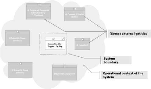
Analyzing the operational context in which the Antarctica Life Support Facility will operate, Anne identifies the following external entities:
– the scientific team: the five scientists involved in the mission. The life support facility provides them with the services needed for their stay and for the accomplishment of their mission;
– the scientific equipment used by the team during the mission. This belongs to the OTL laboratory and will be installed within the life support facility or immediate vicinity. The life support facility must “integrate” this equipment, i.e. provide support and services to allow it to operate, but it is not itself part of the system. Pieces of equipment should therefore be considered a special class of “users” of the life support facility;
– the OTL laboratory: during the mission, the scientists should be in regular contact with their laboratory in Toulouse, using means offered by the life support facility;
– the HyperDrill, which the life support facility must support. It must be considered an external entity for the same reasons mentioned in the case of scientific equipment;
– the Dumont d’Urville station will be responsible for supplying part of the life support facility and will contribute to operational monitoring.
Anne hesitates for a moment concerning the scientific team. In an operational situation, and specifically during coring, part of the team will be outside the life support facility (somewhere on the ice sheet) while the other part of the team will continue to operate within the life support facility buildings. Outside the period of coring, the whole scientific team will normally be inside the life support facility. Is the team, therefore, inside or outside the system? How should we approach this issue when the team is “split in two”?
We should remember that the notion of a system is an abstract one. Thus, although the scientists may be physically present within the facility, considered as an infrastructure in this case, they should be considered as entities external to the “Antarctica Life Support Facility” system. Moreover, from the moment one of the missions of the system focuses directly on the scientists (as in the first mission: “Ensure life support for a team of five scientists”), they cannot themselves form part of this system.
External entities interacting with the system in question are themselves systems (sub-systems of the suprasystem). They should therefore be distinguished by their purpose and missions, and therefore also by the nature of their interactions with the system under consideration. In this case, we should not regard the scientific team as a group of people, but consider the role they play in relation to the system. From a systems engineering viewpoint, we should consider at least two different roles, so two different external entities, for these scientists.
This gives us the following contextual diagram, identifying entities external to the “Antarctica Life Support Facility” in its operational context.
Figure 4.1. Context of the “Antarctica Life Support Facility” system
4.2. System lifecycle
Anne has characterized the operational context of the Antarctica Life Support Facility, beginning by identifying missions and external entities with which the facility will interact. Nevertheless she knows that, before becoming operational, this facility must traverse a certain number of situations, including assembly and dismantling, transportation, installation, etc. In short, the system will be placed in contexts other than the operational context itself. A chronology for the Antarctica Life Support Facility must therefore be constructed from the moment it leaves Toulouse to the point of retirement. Each of these situations involves specific issues and risks, which must be taken into account at this early stage in the process as part of the problem.
Different cycles
We can identify at least three cycles, with interdependences and relative positions:
– the system lifecycle: the “experiences” of the system itself;
– the program lifecycle of the system: this determines the rhythm of the project during study, development, production (etc.) of the system;
– the engineering cycle: the processes and activities involved in engineering the system.
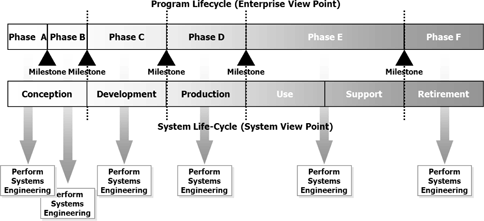
The first two cycles run simultaneously. The program cycle is broken down into phases synchronized with the progression of the system; these phases (and associated milestones) correspond to key stages and states integrated into the life of the system. On the other hand, each program phase involves the deployment of all engineering processes, in differing proportions and for different activities depending on the phase considered.
Various sources of confusion stem from the fact that the same word is often used to designate phases, or processes or activities in each of the cycles. For example, the word “design” may refer to a phase in the life of the system, a program phase or an engineering process!
1) The system lifecycle
A system is a dream, which one day becomes reality; like a person, a system is born, grows into adulthood, and finally dies.
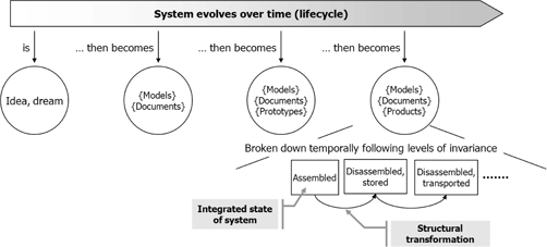
The lifecycle of a system describes the evolution of the system over time. The system passes through a certain number of stages (and consequently transformations). At the outset, a system is only an idea. Then, during an entire phase of the cycle, its existence is virtual (through documentation, models – computerized, mathematical, etc.). Then, little by little, it moves from virtual existence to a physical existence (in the form of a product). At the highest level, the life-cycle of a system is broken down into stages (design, development, production, use, support and retirement [ISO 03]). The stages thus described can be applied to any type of system. They should therefore be declined and described more precisely (particularly by characterizing the system environment). During each of these stages, the system may be confronted with a certain number of situations. These situations are characterized by:
– a particular context in which the system is found (external entities interacting with the system, characterization of the environment, etc.);
– the states/modes of a particular system, which may be induced by the context considered (for example the “night” context may place the system in rest mode, etc.).
In a more academic manner, a temporal analysis breaks a system down into levels of temporal invariance [MEI 98]. Within each level, we may distinguish periods of time during which we may observe the integrity of the structure and behavior of the system (temporal invariance). The non-invariance of a property leads to change. These changes may succeed each other in a continuous or discontinuous manner. It is important to distinguish these levels (and model their dynamics) in order to separate that which belongs to the domain of system evolution (structural aspects) and to its adaptability to a changing environment, missions and technologies, from that which is temporary (operational function). In the life of a system, this passes progressively from an abstraction (dream, idea) to artifacts (models, documents) then to concrete fulfillment in tangible elements (products that are created, assembled, delivered and used).
The passage from abstract to tangible does not involve radical breaks.
The stages and situations of the system lifecycle correspond to states of system integrity, and passages from one state to another can lead to structural modifications in the system.
2) The program cycle
A program consisting of the study, development and deployment, operations (with maintenance of operating conditions) and retirement of a system is not generally carried out in a single step and through a single contract. A program [PMI 09] brings together a set of projects managed in a coordinated manner to obtain a result that could not have been obtained by managing them individually. Each project is broken down into distinct phases, each with specific objectives. Each of these phases places the system into a given, coherent state of description, knowledge and completion. Each phase must be recognized by a milestone or key point that serves, among other things, to provide objective elements for the decision to launch (or otherwise) the following phase. Each of these phases is the object of one or more agreements, managed together in a coordinated and coherent manner at program level in the form of program macro-phases.
These program phases are aligned (or mixed in) with key steps (or stages) of the system lifecycle. This allows us to fix program phases on integrated, coherent and stable states of the system in question, and thus to make important decisions at precise moments in the life of the system.
Numerous documents have standardized the main phases and milestones of programs. Examples include the phases and milestones defined by the ECSS (European Cooperation for Space Standardization [ECS 10] or those of the Department of Defense (DOD Directive 5000 introduced a “Lifecycle Framework for Program Acquisition”, [DAG 10]).
3) The engineering cycle
The process that consists of moving from a need (or dream) to an optimized solution – i.e. the best possible compromise integrating all constraints (cost/time/performance) for the entirety of the phases and situations involved in the system lifecycle – consists of a set of processes. These are: technical project organizational agreement (taken from ISO 15288) [ISO 08a]. Technical processes are often represented in an extended V cycle, or square root cycle.
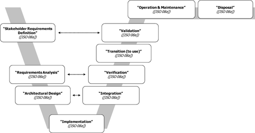
This allows a better visual comprehension of processes, and the association of engineering processes with processes of system integration. This should not, however, be taken to mean that these processes must be carried out in a sequential manner! On the contrary, these different processes are linked, run simultaneously and must be synchronized.
Although [ISO 08a] does not impose an engineering cycle (the way in which these technical processes are arranged), the [EIA 98] and [IEE 05] standards are more explicit on this subject and provide frameworks that link and show synchronization between processes.
The chronology of the Antarctica Life Support Facility, as imagined by Anne, allows her to create a first draft of the general lifecycle, represented (see Figure 4.2) in the form of a partial and incomplete states/transitions diagram.
Up to this point, Anne has concentrated on operational scenarios. She has also identified an abnormal system chronology that would endanger the survival of the team, and would push the life support facility into survival mode. If the conditions or degradations experienced by the facility are too serious for it to be possible to return to normal operations, it would become necessary to evacuate the facility. Anne also identified certain major stages of the system lifecycle, such as deployment, operational qualification and retirement, without – at this stage – clearly identifying triggers, milestones or criteria allowing the passage from one stage to another.
Figure 4.2. First draft of the lifecycle of the Antarctica Life Support Facility

Putting the system into perspective by extending its study in temporal terms, no longer reduced to the “simple” duration of operations, allows us to establish a fuller characterization of the problem. The optimal solution that we must find for this problem cannot be reduced to seeking just a technical or technological solution. Each of the situations the system will encounter will involve a specific environment and context. Studying the system placed into each of these contexts will allow us to identify a certain number of specific constraints and interactions.
Finally, the “right” system is the system that will:
– “resist” or give consideration to all constraints (a base able to withstand the tough climatic conditions of the Antarctic would be no good if it was unable to resist the conditions of transportation to the site);
– allow all planned interactions with different external entities.
To do this, the system may pass through different stages of evolution (unmounted, assembled, etc.), each representing a level of integrity and invariance. This vision of the “right” system often needs to be placed into a perspective of cost and time constraints that prevent the development of the “right” system in favor of a system that arrives on time and within accepted costs.
4.3. Who does the system involve?
Anne has discussed and worked on the project with her manager, Yves, and with a number of other colleagues – scientists involved in the team responsible for the construction of this first vision of the system. However, this is not enough to understand all the necessary information, expectations and limitations involved in the Antarctica Life Support Facility.
Anne must therefore enlarge her circle of contacts to involve other stakeholders with different levels of interest in the facility. She needs to identify all individuals, groups and organizations for whom the system under development presents an issue, risk, interest, etc. Each of these stakeholders, by expressing a point of view concerning the system, will provide Anne with new elements for understanding the problem.
Stakeholders
A stakeholder is a moral or physical entity involved in the project, or whose interests may be positively or negatively affected by the execution of the project in question [PMI 09].
The identification of stakeholders is a key point in the project management approach, but also for requirements engineering (we must simply replace the word “project” with “system” in the above definition). This leads to the constitution – and the management throughout the development cycle – of a list of stakeholders. This identification serves two purposes: to contribute to project management (by understanding the specific objectives of each stakeholder) and to feed into the definition of need (by formalizing the impact of each stakeholder on the system in terms of needs, constraints, risks, etc.). It constitutes a pivot between:
– The technical activities of systems engineering. The successful completion of the task of identifying stakeholders is one of the necessary conditions for the completion of the requirement capture and consolidation process.
– Project management activities. The identification of stakeholders allows us to organize and direct information gathering (with measurements and monitoring of the maturity and completeness of the gathered information) and to allow effective communication between stakeholders and the project.
Each phase of the system lifecycle brings the system into contact with a group of direct or indirect “interactors”. For each, one or more representative stakeholders are identified who are, or represent:
– direct actors in the system lifecycle for a specific stage in this lifecycle, whether during industrialization (marketing, clients, engineering, production, suppliers, etc.) or use (human users, representatives of interacting systems, etc.);
– entities that indirectly limit the definition of the system: regulatory bodies, organizational structures (companies, programs) supporting specific stages of the lifecycle, and all entities providing information on the system environment, whether this be physical (including meteorological and ecological) or cultural, etc.
The identification of stakeholders is one dimension of the problem, as is the characterization of the lifecycle profile or of contexts. Thus, we may base our work on a breakdown of the system lifecycle into phases, modes or situations to provide a structure for the identification of stakeholders. The value of this approach lies in the fact that it provides a structure for reflection, concentrating on a limited number of key factors while being as exhaustive as possible (being sure to identify all needs).
For the moment, Anne’s circle of stakeholders mainly includes representatives of the acquirer, the OTL laboratory via Yves, the head of the Antarctica project, the procurement service and representatives of the main users of the life support facility: the team of scientists involved in the Antarctic expedition. Anne adds to this group as follows in Table 4.1.
Table 4.1. Different stakeholders
| Stakeholder | Type |
|---|---|
| Institut Paul-Emile Victor (formerly the Institut Français pour la Recherche et la Technologie Polaires, French Institute for Polar Research and Technology) | Stakeholder representing several actors in the operational phase: the Dumont d’Urville station, scientific teams in Antarctica, etc. |
| Company supplying the HyperDrill | Stakeholder representing an operational object during the phase of operations |
| The future system supplier | Although the supplier has not yet been identified, it has already been determined in the program that the development of the system will not be carried out by the OTL laboratory but will be effectuated by a subcontractor |
| Telecommunications operators (*) | Stakeholder representing an actor from the operational phase (probably several) |
| Ministry of Ecology and Sustainable Development | Institutional stakeholder presenting regulatory constraints |
| High Administrator of the Terres Australes et Antarctiques Françaises (TAAF), French Southern and Antarctic Territories | Institutional stakeholder presenting regulatory constraints Stakeholder representing an actor in the launch phase (probably several): ship used for access (the Marion Dufresne, the Astrolabe, etc.) |
| Météo France (weather service) | Informative stakeholder during the phase of definition Stakeholder representing an actor in the operational phase |
| Suppliers (*) of scientific data (cartography, climatology, etc.) | Informative stakeholder during the phase of definition |
| Etc. | … |
| (*) Deeper analysis is needed to clearly identify specific stakeholders | |
4.4. Creating a working framework
This first stage allows Anne to create a preliminary draft of the problem to be solved, responding to the following questions:
– The system: Why? What for? The responses to these questions give us a first idea of the operational perimeter of the system (section 4.1.1).
– With whom/what does the system interact? The responses to these questions provide us with a structural vision of the system by identifying external entities in the periphery of the system (section 4.1.2).
– What will the system chronology look like? This is useful in constructing a temporal vision: the system lifecycle (section 4.2).
This structured data (graph {stakeholders} x {external entities} x {phases and situations of lifecycle}) provides a framework for the direction of activities. For this, Anne defines a certain number of contexts in which the system will operate. These contexts:
– define a set of external entities with which the system interacts, which may limit the system or be limited by the presence of the system;
– are defined for one or more situations in the system lifecycle.
Around this structure, a relevant group of participants has an interest in, and possesses information concerning, one or more entities or one or more of the situations facing the system.
This structured information allows Anne to clearly understand her position in terms of information collection and her level of knowledge of different contexts. It therefore becomes an instrument for the efficient direction of her work, providing a measurement of completeness (and therefore of progress) and of what remains to be done.
4.5. Gathering information
Anne has now identified the main stakeholders (although she may discover more in the course of her subsequent activities). We now enter a new, and not particularly easy, stage: that of gathering information on the requirements of these participants. At this stage, having identified sources of information, Anne may begin gathering and analyzing information, with a clear objective of understanding the real needs that the system must fulfill.
Various sorts of useful information exist. It is, of course, possible to find information directly in documents of differing natures: standards, procedures, manuals and documentation for similar or previous systems, etc. Often, however, information is only available indirectly via a complex medium: the human being. These individuals include clients, users, different experts or other stakeholders. They hold essential information, sometimes in a clear and structured form, but more often than not in a “hidden” and non-formalized manner.
The most usual means of collecting information from targeted individuals is to use interviews. Group techniques focusing on group dynamics (brainstorming, role play, etc.) are also effective.
Anne is in luck. The scientific team designated for the expedition is experienced, and certain members have already participated in several polar missions. Anne decides to carry out a series of interviews.
Unfortunately, the first interviews are not a great success: badly directed, enthusiastic or reticent, sometimes centered on technical solutions to a need yet to be formulated, the individuals interviewed provide very little information of real use. A more structured approach is needed.
Tools for questioning
We have no intention of going into the psychological or cultural aspects of interpersonal relations and their impact on the information gathering process here. Our aim is simply to propose tools for structured questioning to allow information to be gathered in a systematic manner.
– 5Why: a technique allowing us to move from obvious to real causes by repeated use (up to five times) of the question “Why?”
– Ishikawa diagrams: a technique for identifying the causes of a problem or the origin of a fact by organizing causes along five axes: environment (milieu), manpower, materials, machinery and methods, sometimes with the addition of measurement (causes corresponding to errors linked to the measurement of the phenomenon under analysis) and management.
– 5W (5W1H): a simple technique that aims to cover all aspects of a question: who, what, where, when, how, why.
– Mind maps: a technique for the hierarchical representation of concepts, ideas, etc., following a tree diagram layout. This is a useful tool for note taking or for use as a visual and dynamic support for questioning (reflection may be relaunched and developed from a node previously left aside). A mind map may be based on words, images, symbols, etc., to best capture the way in which we perceive a subject, synthesize it or promote memorization.
– Users’ stories: a questioning technique based on situations and the description of a scenario with different alternatives. The aim is for the user to tell a “story” in order to analyze all stages, exploring different possible choices and paths.
Interview (using 5Why) with Nathalie (astronomer):
– “During our last mission, a considerable proportion of the saved images proved unusable”.
– “Why?”
– “The telescope (directed towards a distant zone) was frequently upset”.
– “Why?”
– “It was incorrectly calibrated”.
– “Why?”
– “Snow and ice deposits cause reflections and modifications of the optical path. Daily direct visual inspection (and cleaning where needed) was planned, but not always possible.”
– “Why?”
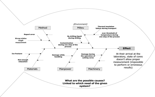
Interview (using an Ishikawa diagram to analyze the problem) with Jean-François (glaciologist):
“You told us that sometimes, on arrival at the laboratory, the core sample is not in a fit state to carry out all required measurements. Could we look at some possible causes of this? What needs does this reveal for the system under consideration?”
Figure 4.3. Example of the use of an Ishikawa diagram
Interview (with note-taking combining 5W1H and mind maps) with Jean- François (glaciologist):
“Concerning your activities outside of the facility…”
Figure 4.4. Example of use of mind-maps and 5W1H

Interview (carried out following a “story” style approach) with Nathalie (astronomer):
– “You’ve already carried out several scientific missions in Antarctica. Could you describe the typical scenario of an expedition from the base for us?”
– (…)
– “And then?”
– (…)
– “And if…?”
Figure 4.5. Image of a story with alternatives

From various discussions with Nathalie and Jean-François, Anne produces a short narrative summary of the scientific work linked to coring:
“The raw cores extracted by the HyperDrill (3 m long) are first identified, then cut into shorter cores (1 m long). These cores then undergo pre-analysis, the results of which are sent to the OTL laboratory. One fourth of the core, cut along the vertical plane, is then extracted for storage on site (for protection against breaks in the refrigeration chain during transport). The remaining core is then placed into a plastic support and stored temporarily, before being sent by convoy to the Dumont d’Urville station. From there, the core will be transported by boat (in a refrigerated hull) then refrigerated truck to the refrigerated storage facilities at the laboratory. Finally, samples will be distributed to the different European laboratories participating in the program”.
Anne can then produce a visual representation of this narrative in the form of a storyboard:
Figure 4.6. “Raw” storyboard of scientific work linked to cores

This storyboard may be formalized to produce an operational scenario using EFFBDs1 ([LON 95] and section 6.6).
Figure 4.7. Operational scenario of scientific work linked to cores

This formalization shows two additional aspects not present in the “raw” storyboard:
– a first idea of the sequence of actions;
– separation of actions for which the Antarctica Life Support Facility is responsible and those that are “outside” and so carried out by external systems (belonging to the context of the Antarctica Life Support Facility).
We should remember the importance of defining the perimeter of the system. This type of representation allows us to set out limits of responsibility, and so de facto the system perimeter, very clearly.
Note also that, in practice, this operational modeling technique presents several advantages:
– it is both relatively simple and expressive, allowing us to represent any operational scenario in a formal manner;
– it is widely readable and understandable by all stakeholders, providing a means of validation for requirement gathering.
Later, mainly in the chapters on operational design (section 6.2), we shall also see that this operational modeling technique also allows model simulation and the verification of certain properties by model-checking [SEI 09]. It therefore constitutes an extremely powerful tool for the systems engineer, allowing modeling, and thus reflection on the system based on successive refinements, in total coherence and without breaks in the formalism throughout the engineering process.
These techniques are just some of the tools needed to capture and understand the viewpoints of different participants, each with their own vocabulary2, preoccupations and aims.
The information gathered in this way is raw material, which must be exploited to feed into and consolidate the different system views under construction (lifecycle, perimeter and contexts, physical and operational views, etc.). We should remember that this process of capturing and consolidating different views is an incremental and iterative operation. Constant to-and-froing between different dimensions of analysis allows us to consolidate a coherent and complete vision of the problem.
4.6. Modeling the context
As we have seen, it is important at this stage to place the system into its context – or contexts, as these may be multiple.
So far, Anne has identified the external entities that interact with the life support facility or limit its use, considering them in relation to stages or situations in the system’s lifecycle. The information collected will allow her to consolidate and enrich this vision and thus determine the interactions, relationships, etc., that link the system to these external entities. These links may be approached from different viewpoints:
– services that are expected and provided: the system provides services to and receives services from its environment. The importance of this point of view is emphasized by the fact that contractual relationships tend to be established on the basis of service provision and not on “simple” products, with a defined and formalized quality of service (QoS);
– constraints: the presence of a system in a context means we must consider the limitations imposed by this context (for example electromagnetic compatibility and resistance to environmental “attacks”: radiation, temperature, climate, etc.);
– operational interfaces: to produce the expected services, the system exchanges flows with the exterior;
– physical3: the system is connected to external entities via physical links4.
Anne will need to model these different viewpoints for the different situations she has envisaged for the life support facility. She will thus obtain a “black box” model of her system, i.e. without breakdown into sub-systems, but seen exclusively through its relationships with external entities (the system “immersed” in its context). She gains a clearer understanding of the contours and perimeter of the system. Anne may now work using the right viewpoint and the correct perspective. She now considers herself to be in a position to extract needs relating to her problem (diagrams produced as part of this context model will be presented in section 4.9).
However, Anne still faces some difficulties. She feels that the “simple” identification of the principal missions of the system, even when these are placed into context (exchange of flows with external entities, relationships with external entities, etc.) is not sufficient for the clear expression of the goals and expectations of the system.
How can final users and other stakeholders feel completely satisfied with an expression of their needs that is reduced to the succinct statement of the main missions? In other words, how can they give their consent based on this expression? Moreover, Anne has a quantity of information that she has not yet used, obtained by interviewing stakeholders and through information gathering activities.
4.7. Understanding and defining goals
Anne uses two important words in her reflections: “goal” and “satisfaction”. An engineering methodology exists that allows us to reason using goals and their satisfaction – a goal-oriented approach known as KAOS methodology5.
Broadly speaking, this methodology is based on successive refinements of the “goals”6 of the system under consideration in order to yield (sub)goals at a satisfactory level of granularity.
The approach also allows us, while identifying these goals, to model and reflect on the links between these goals, above and beyond refinement links: conflicts, obstacles, etc.
Anne therefore decides that in order to put some order into her ideas and into all of the information she has been able to gather she will use this approach to structure and consolidate information to identify the requirements of her system.
A short introduction to KAOS methodology
KAOS methodology is destined for use mainly in software or information system engineering, placing the object of study – the system – in its global context (external environment).
This highly relevant approach may be transposed for use in requirements engineering and engineering the demands of complex systems.
Here, we shall look at the use of KAOS methodology in requirements engineering. Chapter 5 will return to this subject to look at the use of KAOS in engineering the demands of complex systems.
Fuller descriptions of KAOS methodology can be found in [LAM 04], [LAM 08] and [LAM 09].
Four types of models form the basis of this methodology (see figure):
– a goal model, responding to the questions “what?”; “why?” and “how?”. This is the model that Anne will use to structure her reflection;
– a responsibility model, responding to the question “who?”;
– a model of operations, responding to the questions “do what?” and “when?”;
– an object model, responding to the question “about what?”.
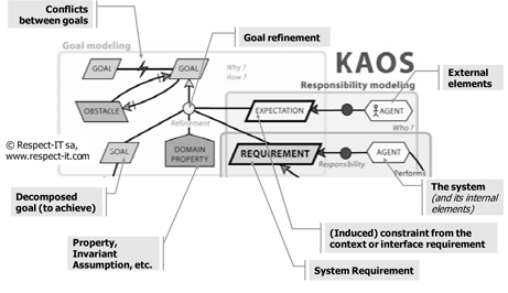
The goal model allows us to structure goals in the form of acyclic-oriented graphs based on information gathered previously.
A goal in the graph may be refined to give a collection of sub-goals that describe how the refined goal is attained, possibly with the addition of domain properties.
A goal is an “objective” to be reached by the system, a prescriptive declaration of intent of the system considered. A domain property is a descriptive expression of the environment (a constant, a hypothesis, a property, etc.).
A sub-goal of the graph is justified by at least one other goal and is included as a refinement of this goal or goals.
At this stage, we may state simply that a parent goal is satisfied if and only if its refinement is satisfied and the domain properties are verified.
We can express this as follows:
{refined goal, domain properties} |= parent goal
We can distinguish two categories of goals:
– functional goals: state the intent underpinning a system service;
– non-functional goals: state a quality or constraint on service provision or development.
These can be of two different types:
– behavioral goals: these goals represent behaviors to satisfy, where this “satisfaction” may be expressed formally and thus without ambiguity (an imperative goal must be able to be translated or expressed using a formal system, such as a mathematical logic);
– “soft” goals: there are no clear and quantifiable criteria to allow us to give a formal measurement of the satisfaction of goals of this type (for example, a goal such as “reduce driver stress”). Often, these goals are used to characterize a preference or criterion for the evaluation of different alternative solutions.
Two goals may be in conflict if, under certain conditions, they cannot both be attained at the same time.
An agent, in KAOS, is an active object that carries out actions to achieve goals. An agent may be internal or external to the system. Staying with KAOS terminology, a final goal that is assigned to an external agent is an expectation. A final goal that is assigned to an internal agent is a demand.
Applied to the domain of engineering the needs of complex systems, this gives us:
– a final goal assigned to an external component, i.e. a component of the context of the system considered, potentially creates:
- constraints/expectations linked to external components,
- interface requirements with the system concerned,
- a final need assigned to an internal component (i.e. to the system itself, at this level of study and within a black box vision of the system) leads to the identification of a need in relation to this system.
These principles and their use in the context of engineering the needs of complex systems are marked in the following extract of the KAOS meta-model. We shall introduce the notion of obstacles and anti-models in Chapter 5.
The refinement of goals
The basic method for refining a goal is to respond to the question “How can we say that a goal has been achieved?”, and thus obtain the elements needed to satisfy a given goal.
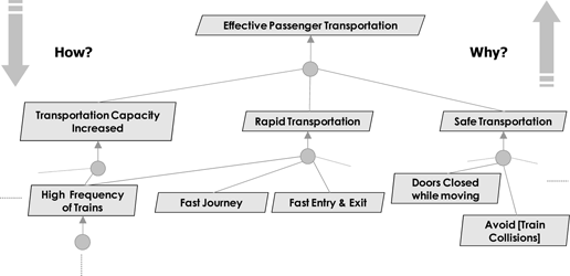
Anne therefore uses this approach to refine one of the essential “goals” of the Life Support Facility: to “provide life support”. This allows her to structure information that, for the moment, is rather dispersed, and thus to reconstitute and complete the puzzle.
Figure 4.8. Graph of “goals” of the Antarctica Life Support Facility
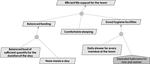
Effectively, the KAOS approach allows us to combine a top-down approach (a response to the question “how?”) and a bottom-up approach (responding to the question “why?”).
The work of capturing information within groups, even using structured techniques (see section 4.5), cannot claim to confine individuals to a single way of thinking: they will always tend to think in both directions, and this is a positive attribute! In this case, the goal model creates clear added value by allowing a structured assembly of the various contributions of stakeholders.
4.8. Modeling the domain
In the course of her progression through the project, Anne has improved her understanding of different aspects of a polar expedition. Through documentary analysis and interviews, she has discovered the multiple professions of different participants, each with their own specificities, vocabulary, etc. This comprehension was not easy to come by: Anne needed to understand the jargon used in different contexts and clarify terminology that was, at times, ambiguous only to discover that the same terms sometimes have different meanings depending on the individuals using them.
Anne understands that the mastery of this domain knowledge is one of the keys to success of the project in terms of communication and mastering requirements. She must ensure that the different stakeholders in the engineering cycle share a common vocabulary and an understanding of the system environment as early as possible in the process. This understanding involves the identification of concepts, principles and rules applicable to the problem domain.
The formalization of the domain of knowledge linked to the stage7 of use of the system will allow Anne to bring together the different participants involved around a shared and consistent body of knowledge. First and foremost, this will constitute a common foundation from which needs will be captured and formalized, bringing the “formulated need” closer to the real need. This corpus constitutes a useful (and usually indispensable) point of reference during the phase of need analysis and the reformulation of these needs as a series of demands.
Next, as industrial suppliers (or bidders during the contracting phase) are not usually experts in the domain, this corpus will allow them to gain a better grasp of the problem. This will contribute to a reduction in the possibility of misunderstandings between the “understood and reformulated need” (supplier or bidders) and the “formulated need”.
Introduction to domain analysis
The domain and its extent
The first definition of a system places it in a given environment: the system responds to a given need in a target environment. The domain is the set of knowledge relating to the real-world situation of the system. It exists outside of the system developed for this environment. However, mastery of the domain is essential for understanding and analysis of the problem to which the system must respond.
A simple and particularly useful example is that of a three-color traffic light system on a pedestrian crossing. The basic idea is simple: a set of three-colored lights, timed and synchronized, is used for vehicles and pedestrians. However, the successful operation of this system is based on a complex set of information contained in the rules of the road. The driver and the pedestrian must understand the color codes involved; the pedestrian must be able to apprehend the information shown by the lights; and timings must be in accordance with speed limits, braking capacities, the reaction time of the driver, the width of the route, the speed of the pedestrian, etc.
In the case of an approach based on product lines or families of use, domain analysis may be constructed in a generic manner, with a level of abstraction that allows reuse by all target systems in the domain under consideration.
What information should be included in the body of knowledge?
The following list is a proposed typology of information to consider in creating a relevant corpus of knowledge for a given domain. It is inspired by the operational view used in the NATO Architecture Framework [NAF 07]:
– Organizational environment and actors: here, we identify the organizations and different actors involved in the system environment, with the aim of understanding how responsibilities are shared between actors and the collaborations involved. This work is particularly useful for the identification of stakeholders (see section 4.3).
– Operational objects: this covers all real-world objects that the domain actors use or through which they communicate. These objects may have a physical presence (drill, ice core) or be conceptual in nature (path, itinerary). In a domain model, an operational object may be represented in the form of an information object (see below).
– Operational rules and processes (or business rules and processes): the system is part of a broader operational schema, in which actors collaborate in activities to produce certain results. From this perspective (responsibility, causality and sequentiality), a process is a set of activities triggered by an event that transforms input into output. The operational environment may therefore be described using a process map, the understanding of which allows us to cast light on contexts (see section 4.6) and to structure attainment goals (see section 4.7). This description may be added to by the identification of operational rules (regulations, directives, etc.) that limit actors in the way in which they implement operational processes.
– Information: an information object is the abstraction, in the form of data, of an operational object. It contains data that are useful and necessary for the description of the object (with the aim of operational use). Information objects are produced or used by different actors to successfully carry out the tasks for which they are responsible. It is thus possible to formalize complete information flows describing the path taken by information (between actors in the domain): capture, processing, storage, distribution, use, etc.
How do we structure and represent this information?
Having defined a first typology of information to collect, we must now think about ways to structure this domain information. Several approaches are possible and may be combined to obtain the best results.
– Classification (or taxonomy). This involves the definition and application of a schema for the classification of information. The classic diagram is hierarchical and follows a tree diagram pattern (definition of categories and sub-categories supporting relationships of the type “is a set of”, “is a type of”, etc.).
– Ontology. This is a data model involving a set of terms and concepts and the relationships between them. We can consider an ontology as describing objects, classes (types or collections of objects), the attributes of these objects or classes, and rules of inference. For reasons of clarity and completeness, it is interesting to present the ontology in graphical form.
– Dictionary or glossary. Textual definition of each term and concept. This may be an alternative to the other forms of organization of the domain information, or a textual reformulation of the viewpoint expressed through an entity–relationship model. All of this is only a partial representation of the real world – the object of conceptualization activities – constructed following a specific representational schema. For this reason, it can be considered to be a model of the domain. To facilitate the organization (taxonomic, ontological, etc.) of domain information, the use of a structured representation is recommended. This serves both as a support for construction and as a means of communication.
The appropriate representation is the entity–association model that allows us to create a data model in the form of entities (enriched with attributes) and associations between these entities. Multiple notations exist allowing the description of such models, and may be graphical or textual. UML [FOW 03, BOO 05] is one graphical notation that may be used, allowing us to build entity– association models:
– the class diagram offers all the tools needed to abstract real-world entities and the associations (semantic or taxonomic) that link them;
– the object diagram is both the point of departure for the analysis (support for the identification of real objects) and the final means of verification (by instantiation of the class model).
One difficulty is in fixing the limit of the domain (or domains) for consideration. For her project, Anne understands that she will need to look at polar domains: life in zones of extreme cold, arctic meteorology, human and scientific activities in the Antarctic, etc. She may also need to look at the domain of glaciology (the main activity of system users). She will need to interact with stakeholders with expertise and practical experience in the relevant domain in order to extract relevant knowledge needed for the capture and formulation of needs.
The domain objects are often extracted from interview reports or from raw information. For example, from her first information collection activities concerning the launch and operation of the Antarctic Life Support Facility, Anne was able to produce the following summary:
– “In normal conditions, the Life Support Facility has a radio link to the Dumont d’Urville and Mario Zucchelli stations, and a satellite link to the OTL laboratory. During the transportation of material or passengers, it also has a communication link to the terrestrial convoy (from Dumont d’Urville) or the airplane (from Mario Zucchelli) carrying materials or passengers. During drilling activity, the scientific team is split into two: one section within the facility, the other part outside”.
– “The Dumont d’Urville station is managed by the Paul-Emile Victor French Polar Institute. The Mario Zucchelli station is managed by the Italian PNRA (Programma Nazionale di Ricerche in Antartide)”.
The domain objects identified by Anne are shown in bold in the text. A report identifying objects of the business processes and rules type in this way shows that:
– “To start with, all human activity in Antarctica is subject to the rules defined by the Antarctic Treaty System concerning waste management (…). For example, an annex to the treaty lists the categories of waste which must be eliminated and sets out modes of waste storage and elimination.”
Another report provides a narrative description of the coring scenario, identifying business processes and rules type objects:
– “The raw cores extracted by the HyperDrill (3 m long) are first identified, then cut into shorter cores (1 m long). These cores then undergo pre-analysis, the results of which are sent to the OTL laboratory. One fourth of the core, cut along the vertical plane, is then extracted for storage on-site (for protection against breaks in the refrigeration chain during transport). The remaining core is then placed into a plastic support and stored temporarily, before being sent by convoy to the Dumont d’Urville station. From there, the core will be transported by boat (in a refrigerated hull), then refrigerated truck to the refrigerated storage facilities at the laboratory. Finally, samples will be distributed to the different European laboratories participating in the program.”
This same report also identifies data (information type objects):
– “Identity slip attached to an ice core during processing (order number in the extraction sequence, depth of extraction, etc.). Pre-analysis data file for a set of cores sent from the life support facility to the OTL laboratory”.
Working on this point, Anne’s analysis leads her to global consideration of the flow of data from the pre-analysis of a core. This includes measurement in the Life Support Facility laboratory, its possible pre-processing, its consolidation in a data set, the sending of the data set to the OTL laboratory, its archiving in the laboratory database, etc. (replacing information type objects within an information flow.)
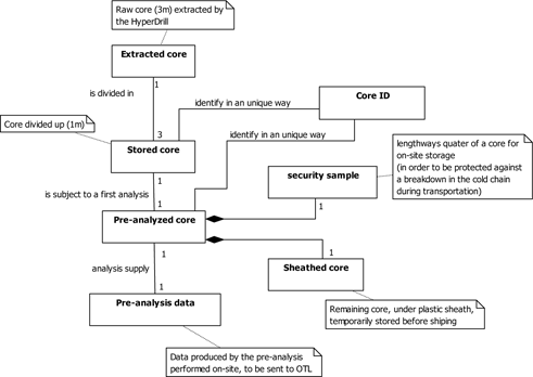
Anne abstracts and constructs an entity-relation schema from this information (UML class diagram) as shown in Figure 4.9.
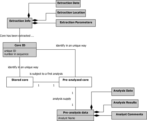
In the course of her analysis, Anne will also make additions to this model using the description of data characterizing certain operational objects (information type objects). For example, the identity slip attached to a core during processing will be characterized by the following information (among other things):
– unique identifier;
– date and location of extraction;
– characteristics of extraction (depth, etc.);
– sequence order number;
– etc.
Figure 4.9. Entity-relation model linked to the scientific mission of coring
In the same way, for pre-analysis data we find:
– analyst name;
– date of analysis;
– results of analysis;
– comments;
– etc.
This allows Anne to enrich her model in the way shown in Figure 4.10.
Anne now has all the tools she requires in order to structure the body of knowledge that is useful and necessary for the capture and formulation of need. She may use models and a glossary for the domain to establish elements of a reference language shared by all engineering actors; this language is destined for use throughout all subsequent stages of the engineering cycle.
Figure 4.10. Detail of the entity-relation model linked to the scientific mission of coring
4.9. Defining stakeholder requirements and constraints
Upon arriving at this stage, the engineering work is almost complete. Anne summarizes what she has learnt in terms of engineering elements:
– she has improved her understanding of the domain using a block of knowledge from which she has extracted elements of language for use in the clear and nonambiguous description of requirements (see section 4.8);
– she has understood the context of operations of the system. Anne has even modeled this context following different viewpoints (functional, physical, etc.). She thus has a precise vision of the perimeter of the system (see section 4.6);
– she has placed the system into its lifecycle (see section 4.2);
– she has organized the expectations of the system as a collection of goals (or missions) that she has broken down into a set of sub-goals (see section 4.7).
These engineering elements are the result of reflection, synthesis, abstraction and value creation in relation to contextual information. This information was obtained by methodical research and collection of information from stakeholders and other information sources. Anne directed and monitored the progress of this activity by the use of a relevant framework, in this case based on a graph showing {stakeholders} X {external entities} X {lifecycle phases and situations}.
All that remains is for Anne to provide a written expression of the needs and expectations of different stakeholders in the form of a document generally known as the specification.
As stated earlier in the context of KAOS goal models, this is carried out by directly extracting engineering elements and models translated into a textual form. This textual form, possibly accompanied by graphics, is better suited for communication with different actors involved in this expression of requirements:
– various stakeholders for validation;
– the quality team, for verification;
– the head of the project (or program) for approval;
– purchasing services, to contractualize supply with a supplier to be selected;
– potential suppliers, then the selected supplier, to gain a shared understanding of expectations and propose a suitable solution.
We now have some examples of the identification and textual expression of needs8 produced through engineering work.
From the viewpoint of expected services (see section 4.6), Anne will naturally express, as accurately as possible, needs in terms of service (using vocabulary established by the domain model, in bold and underlined in Figure 4.11).
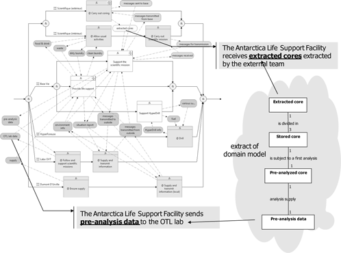
From the operational viewpoint (see section 4.6), Anne will logically obtain needs in terms of the operational interface, but also, as above, possible information concerning requirements in terms of performance, efficiency, quality of service, etc. Once again, we note the use of vocabulary defined by the domain model.
Figure 4.11. Extraction of the expression of service requirements
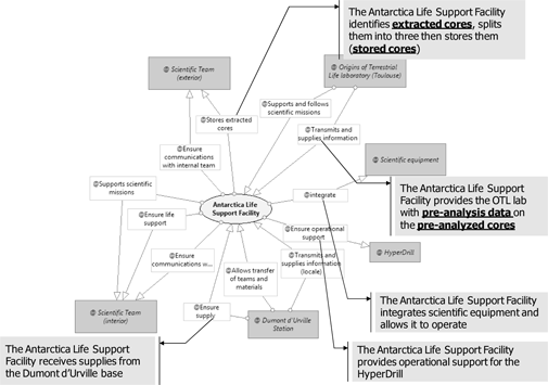
Figure 4.12. Extraction of the expression of functional interface requirements
From the physical viewpoint (see section 4.6) Anne will mainly be able to extract needs in terms of the physical interface and, including supplementary analyses, identify constraints in terms of performance, protocols, etc., relating to these links.
Figure 4.13. Extraction of needs: physical interface
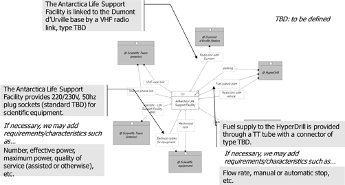
These different models allow us to obtain all of the needs of the system (as a black box) in relation to its context. A system never exists in isolation. Its very existence creates a network of interactions with components of the context. The goal model (section 4.7) is also a rich source of information, and will allow Anne to add efficiency requirements (QoS), operational requirements and the constraints of the Antarctica Life Support Facility to the expected service requirements.
Figure 4.14. Extraction of requirements from the goal model

4.10. Things to remember: stakeholder-requirements engineering
Anne has now carried out stakeholder-requirements engineering, defining the expectations and constraints of stakeholders (see Stakeholder Requirements Definition in [ISO 08a]). As with all technical engineering activities, this is an activity involving: (i) transformation (ii) based on reasoning and (iii) production of added value:
(i) Transformation: from an idea – sometimes barely formulated – and multiple stakeholder requirements, relating to one (or more) context(s) and a structured set of needs and constraints.
(ii) Based on reasoning:
- through an approach punctuated by questioning: “asking the right questions at the right time” (why the system exists, what the system should do, who is involved in the system, who it interacts with, etc.);
- which considers the system in the temporal perspective of its lifecycle;
- which takes a resolutely external viewpoint: the system is considered a black box, immersed in a given context (or, in fact, several contexts linked to the lifecycle);
- which studies and therefore models the system in these contexts following complementary and coherent points of view: services and operations, constraints, flow exchanges, physical links, etc.;
- which conceptualizes the expectations of shareholders and the information collected through formalized and structured elements of engineering (goal graphs, domain models, etc.).
(iii) Production of added value:
- the questioning approach allows us to correctly comprehend the problem and capture all necessary and relevant information;
- the constitution of temporal and contextual models of the system allows us to grasp all dimensions of the system with the aim of producing an exhaustive definition of the problem;
- the creation of goal models and semantic models allows us to create a complete and coherent model of the requirements and constraints of the system in question.
Stakeholder-requirements engineering is an activity that involves the capture, organization and contextualization of useful information for the definition of a problem. As with any engineering activity, it cannot be reduced to the production of documents. Even if, finally, this activity takes a concrete form with the creation of a specification, the latter is merely a textual view (in natural language, expressed using the vocabulary of the domain) with the possible addition of diagrams to clarify understanding, taken from all available engineering elements – the tip of the iceberg, so to speak!
4.11. Bibliography
[BOO 05] BOOCH G., RUMBAUGH J., JACOBSON I., Unified Modeling Language User Guide, Addison-Wesley, London, 2005.
[DAG 10] DAG (Defense Acquisition Guidebook), www.dag.dau.mil/Pages/Default.aspx, 2010.
[ECS 10] ECS (European Cooperation for Space Standardization), www.ecss.nl/, 2010.
[EIA 98] EIA, ANSI/EIA 632 – Processes for Engineering a System, 1998.
[FOW 03] FOWLER M. et al., UML Distilled: A Brief Guide to the Standard Object Modeling Language, Addison-Wesley, Boston, USA, 2003.
[IEE 05] IEEE, Standard for Application and Management of the Systems Engineering Process, IEEE 1220-2005, IEEE, 2005.
[ISO 03] ISO, Systems Engineering – A guide for the application of ISO/IEC 15288, ISO/IEC TR 19760, ISO, 2003.
[ISO 08a] ISO, Systems Engineering, System Life Cycle processes, ISO/IEC 15288, ISO, 2008.
[LAM 04] VAN LAMSWEERDE A., “Goal-oriented requirements engineering: a roundtrip from research to practice”, Proceedings of RE’04, 12th IEEE Joint International Requirements Engineering Conference, Kyoto, Japan, September 2004.
[LAM 08] VAN LAMSWEERDE A., “Requirements engineering: From craft to discipline”, Proceedings FSE’2008, 16th ACM Sigsoft Intl. Symposium on the Foundations of Software Engineering, (Invited Paper for the ACM Sigsoft Outstanding Research Award), Atlanta, USA, November 2008.
[LAM 09] VAN LAMSWEERDE A., Requirements Engineering: From System Goals to UML Models to Software Specifications, John Wiley & Sons, New York, USA, 2009.
[LON 95] LONG J., “Relationships between common graphical representations in systems engineering”, 5th International Symposium of the INCOSE, St. Louis, INCOSE, Saint- Louis, July 1995.
[MEI 98] MEINADIER J.-P., Ingénierie et Intégration des Systèmes, Hermès, Paris, France, 1998.
[NAF 07] NATO, Architectural Framework (NAF), NATO, 2007.
[PMI 09] PMI (Project Management Institute), A Guide to the Project Management Body of Knowledge (PMBOK® Guide) (3rd edition), PMI, 2009.
[SEI 09] SEIDNER C., Vérification des eFFBDs: Model-checking en Ingénierie Système, PhD thesis, University of Nantes, Nantes, France, 2009.
1 Chapter written by Philippe THUILLIER and Jean-Luc WIPPLER.
1 Enhanced Functional Flow Block Diagram.
2 In fact, one of the following stages (section 4.8) consists of creating an ontology (objective and shared vision of the domain, expressed through a structured and coherent set of terms and concepts, with the relationships that link them).
3 The term “organic” may also be used.
4 Note that “physical” does not necessarily mean material, but rather that it obeys physical laws. For example, a data link may be supported by a wired or wireless medium. Both media are based on the operation of electromagnetic laws.
5 These methods are also known as “GORE”: Goal Oriented Requirement Engineering.
6 Note that the word should be considered in light of the definition and semantics used in KAOS methodology. It should not be confused with the purpose of a system, which may also be described as an “aim” (as used by Joël de Rosnay in his definition of a system: “A system is a set of elements in dynamic interaction organized in relation to an aim”.). In this particular context, the word “goal”, as we shall see in the presentation of KAOS methodology, should be considered a synonym of “objective”. This can be a source of linguistic confusion. KAOS is a “goal-oriented” methodology as regards the general definition of a system: “final goal → missions → objectives”.
The authors provide two definitions of this acronym: “Knowledge Acquisition in autOmated Specification” and “Keep All Objects Satisfied”.
7 This point of view may be generalized by considering that, at each stage of the system lifecycle, the stakeholders involved must share a consistent vision of their shared domain. Thus, it would be a good idea for Anne, her team and all stakeholders involved in the definition phase to have a shared vision of the domain of engineering (through a data and process model, for example).
8 Real values and exact names are not given here; we are not interested in providing a precise and definitive specification in this project, but in illustrating the engineering process.
