
Chapter 2
Overview of the LTE Physical Layer
The focus of this book is the LTE (Long Term Evolution) radio access technology and particularly its PHY (Physical Layer). Here, we will highlight the major concepts related to understanding the technology choices made in the design of the LTE PHY radio interface. Focusing on this topic will best explain the remarkable data rates achievable by LTE and LTE-Advanced standards.
LTE specifies data communications protocols for both the uplink (mobile to base station) and downlink (base station to mobile) communications. In the 3GPP (Third Generation Partnership Project) nomenclature, the base station is referred to as eNodeB (enhanced Node Base station) and the mobile unit is referred to as UE (User Equipment).
In this chapter, we will cover topics related to PHY data communication and the transmission protocols of the LTE standards. We will first provide an overview of frequency bands, FDD (Frequency Division Duplex) and TDD (Time Division Duplex) duplex methodologies, flexible bandwidth allocation, time framing, and the time–frequency resource representation of the LTE standard. We will then study in detail both the downlink and uplink processing stacks, which include multicarrier transmission schemes, multi-antenna protocols, adaptive modulation, and coding schemes and channel-dependent link adaptations.
In each case, we will first describe the various channels that connect different layers of the communication stacks and then describe in detail the signal processing in the PHY applied on each of the downlink and uplink physical channels. The amount of detail presented will be sufficient to enables us to model the downlink PHY processing as MATLAB® programs. In the subsequent four chapters we will iteratively and progressively derive a system model from simpler algorithms in MATLAB.
2.1 Air Interface
The LTE air interface is based on OFDM (Orthogonal Frequency Division Multiplexing) multiple-access technology in the downlink and a closely related technology known as Single-Carrier Frequency Division Multiplexing (SC-FDM) in the uplink. The use of OFDM provides significant advantages over alternative multiple-access technologies and signals a sharp departure from the past. Among the advantages are high spectral efficiency and adaptability for broadband data transmission, resistance to intersymbol interference caused by multipath fading, a natural support for MIMO (Multiple Input Multiple Output) schemes, and support for frequency-domain techniques such as frequency-selective scheduling 1.
The time–frequency representation of OFDM is designed to provide high levels of flexibility in allocating both spectra and the time frames for transmission. The spectrum flexibility in LTE provides not only a variety of frequency bands but also a scalable set of bandwidths. LTE also provides a short frame size of 10 ms in order to minimize latency. By specifying short frame sizes, LTE allows better channel estimation to be performed in the mobile, allowing timely feedbacks necessary for link adaptations to be provided to the base station.
2.2 Frequency Bands
The LTE standards specify the available radio spectra in different frequency bands. One of the goals of the LTE standards is seamless integration with previous mobile systems. As such, the frequency bands already defined for previous 3GPP standards are available for LTE deployment. In addition to these common bands, a few new frequency bands are also introduced for the first time in the LTE specification. The regulations governing these frequency bands vary between different countries. Therefore, it is conceivable that not just one but many of the frequency bands could be deployed by any given service provider to make the global roaming mechanism much easier to manage.
As was the case with previous 3GPP standards, LTE supports both FDD and TDD modes, with frequency bands specified as paired and unpaired spectra, respectively. FDD frequency bands are paired, which enables simultaneous transmission on two frequencies: one for the downlink and one for the uplink. The paired bands are also specified with sufficient separations for improved receiver performance. TDD frequency bands are unpaired, as uplink and downlink transmissions share the same channel and carrier frequency. The transmissions in uplink and downlink directions are time-multiplexed.
Release 11 of the 3GPP specifications for LTE shows the comprehensive list of ITU IMT-Advanced (International Telecommunications Union International Mobile Telecommunication) frequency bands 2. It includes 25 frequency bands for FDD and 11 for TDD. As shown in Table 2.1, the paired bands used in FDD duplex mode are numbered from 1 to 25; the unpaired bands used in TDD mode are numbered from 33 to 43, as illustrated in Table 2.2. The band number 6 is not applicable to LTE and bands 15 and 16 are dedicated to ITU Region 1.
Table 2.1 Paired frequency bands defined for E-UTRA

Table 2.2 Unpaired frequency bands defined for E-UTRA
| Operating band index | Uplink and downlink operating band frequency range (MHz) | Duplex mode |
| 33 | 1900–1920 | TDD |
| 34 | 2010–2025 | TDD |
| 35 | 1850–1910 | TDD |
| 36 | 1930–1990 | TDD |
| 37 | 1910–1930 | TDD |
| 38 | 2570–2620 | TDD |
| 39 | 1880–1920 | TDD |
| 40 | 2300–2400 | TDD |
| 41 | 2496–2690 | TDD |
| 42 | 3400–3600 | TDD |
| 43 | 3600–3800 | TDD |
2.3 Unicast and Multicast Services
In mobile communications, the normal mode of transmission is known as a unicast transmission, where the transmitted data are intended for a single user. In addition to unicast services, the LTE standards support a mode of transmission known as Multimedia Broadcast/Multicast Services (MBMS). MBMS delivers high-data-rate multimedia services such as TV and radio broadcasting and audio and video streaming 1.
MBMS has its own set of dedicated traffic and control channels and is based on a multicell transmission scheme forming a Multimedia Broadcast Single-Frequency Network (MBSFN) service area. A multimedia signal is transmitted from multiple adjacent cells belonging to a given MBSFN service area. When the content of a single Multicast Channel (MCH) is transmitted from different cells, the signals on the same subcarrier are coherently combined at the UE. This results in a substantial improvement in the SNR (signal-to-noise ratio) and significantly improves the maximum allowable data rates for the multimedia transmission. Being in either a unicast or a multicast/broadcast mode of transmission affects many parameters and components of the system operation. As we describe various components of the LTE technology, we will highlight how different channels, transmission modes, and physical signals and parameters are used in the unicast and multicast modes of operations. The focus throughout this book will be on unicast services and data transmission.
2.4 Allocation of Bandwidth
The IMT-Advanced guidelines require spectrum flexibility in the LTE standard. This leads to scalability in the frequency domain, which is manifested by a list of spectrum allocations ranging from 1.4 to 20 MHz. The frequency spectra in LTE are formed as concatenations of resource blocks consisting of 12 subcarriers. Since subcarriers are separated by 15 kHz, the total bandwidth of a resource block is 180 kHz. This enables transmission bandwidth configurations of from 6 to 110 resource blocks over a single frequency carrier, which explains how the multicarrier transmission nature of the LTE standard allows for channel bandwidths ranging from 1.4 to 20.0 MHz in steps of 180 kHz, allowing the required spectrum flexibility to be achieved.
Table 2.3 illustrates the relationship between the channel bandwidth and the number of resource blocks transmitted over an LTE RF carrier. For bandwidths of 3–20 MHz, the totality of resource blocks in the transmission bandwidth occupies around 90% of the channel bandwidth. In the case of 1.4 kHz, the percentage drops to around 77%. This helps reduce unwanted emissions outside the bandwidth, as illustrated in Figure 2.1. A formal definition of the time–frequency representation of the spectrum, the resource grid, and the blocks will be presented shortly.
Table 2.3 Channel bandwidths specified in LTE
| Channel bandwidth (MHz) | Number of resource blocks |
| 1.4 | 6 |
| 3 | 15 |
| 5 | 25 |
| 10 | 50 |
| 15 | 75 |
| 20 | 100 |
Figure 2.1 Relationship between channel bandwidth and number of resource blocks

2.5 Time Framing
The time-domain structure of the LTE is illustrated in Figure 2.2. Understanding of LTE transmission relies on a clear understanding of the time–frequency representation of data, how it maps to what is known as the resource grid, and how the resource grid is finally transformed into OFDM symbols for transmission.
Figure 2.2 LTE time-domain structure

In the time domain, LTE organizes the transmission as a sequence of radio frames of length 10 ms. Each frame is then subdivided into 10 subframes of length 1 ms. Each subframe is composed of two slots of length 0.5 ms each. Finally, each slot consists of a number of OFDM symbols, either seven or six depending on whether a normal or an extended cyclic prefix is used. Next, we will focus on the time–frequency representation of the OFDM transmission.
2.6 Time–Frequency Representation
One of the most attractive features of OFDM is that it maps explicitly to a time–frequency representation for the transmitted signal. After coding and modulation, a transformed version of the complex-valued modulated signal, the physical resource element, is mapped on to a time-frequency coordinate system, the resource grid. The resource grid has time on the x-axis and frequency on the y-axis. The x-coordinate of a resource element indicates the OFDM symbol to which it belongs in time. The y-coordinate signifies the OFDM subcarrier to which it belongs in frequency.
Figure 2.3 illustrates the LTE downlink resource grid when a normal cyclic prefix is used. A resource element is placed at the intersection of an OFDM symbol and a subcarrier. The subcarrier spacing is 15 kHz and, in the case of normal cyclic prefix, there are 14 OFDM symbols per subframe or seven symbols per slot. A resource block is defined as a group of resource elements corresponding to 12 subcarriers or 180 kHz in the frequency domain and one 0.5 ms slot in the time domain. In the case of a normal cyclic prefix with seven OFDM symbols per slot, each resource block consists of 84 resource elements. In the case of an extended cyclic prefix with six OFDM symbols per slot, the resource block contains 72 resource elements. The definition of a resource block is important because it represents the smallest unit of transmission that is subject to frequency-domain scheduling.
Figure 2.3 Resource elements, blocks, and grid

As we discussed earlier, the LTE PHY specification allows an RF carrier to consist of any number of resource blocks in the frequency domain, ranging from a minimum of six resource blocks up to a maximum of 110 resource blocks. This corresponds to transmission bandwidths ranging from 1.4 to 20.0 MHz, with a granularity of 15 kHz, and allows for a very high degree of LTE bandwidth flexibility. The resource-block definition applies equally to both the downlink and the uplink transmissions. There is a minor difference between the downlink and the uplink regarding the location of the carrier center frequency relative to the subcarriers.
In the uplink, as illustrated in Figure 2.4, no unused DC subcarrier is defined and the center frequency of an uplink carrier is located between two uplink subcarriers. In the downlink, the subcarrier that coincides with the carrier-center frequency is left unused. This is shown in Figure 2.5. The reason why the DC subcarrier is not used for downlink transmission is the possibility of disproportionately high interference.
Figure 2.4 Resource blocks and DC components of the frequency in uplink transmission

Figure 2.5 Resource blocks and DC components of the frequency in downlink transmission

The choice of 15 kHz as subcarrier spacing fits perfectly with the OFDM mandate that turns a frequency-selective channel into a series of frequency-flat subchannels with fine resolution. This is turn helps the OFDM to efficiently combat frequency-selective fading by using a bank of low-complexity equalizers that apply to each of the flat-faded subchannels in the frequency domain.
2.7 OFDM Multicarrier Transmission
In the LTE standard, the downlink transmission is based on an OFDM scheme and the uplink transmission is based on a closely related methodology known as SC-FDM. OFDM is a multicarrier transmission methodology that represents the broadband transmission bandwidth as a collection of many narrowband subchannels.
There are multiple steps involved in OFDM signal generation. First, modulated data are mapped on to the resource grid, where they are organized and aligned in the frequency domain. Each modulated symbol ak is assigned to a single subcarrier on the frequency axis. With N subcarriers occupying the bandwidth with a subcarrier spacing of Δf, the relationship between the bandwidth and subcarrier spacing is given by:
2.1 ![]()
Each subcarrier fk can be considered an integer multiple of subcarrier spacing:
2.2 ![]()
The OFDM modulator consists of a bank of N complex modulators, where each modulator corresponds to a single subcarrier. The OFDM modulated output x(t) is thus expressed as:
2.3 
Assuming that the channel sample rate is Fs and the channel sample time is Ts = 1/Fs, the discrete-time representation of the OFDM modulator can be expressed as:
2.4 
The OFDM modulation lends itself naturally to an efficient implementation based on Inverse Fast Fourier Transform (IFFT). After the OFDM modulation, an OFDM symbol is generated and a cyclic prefix is added to the modulated signal. Insertion of a cyclic prefix is essentially copying of the last part of the OFDM symbol to its beginning.
2.7.1 Cyclic Prefix
Cyclic prefix insertion is an important function during OFDM signal generation. A cyclic prefix is necessary to prevent interference from previously transmitted OFDM symbols. The intersymbol interference can be viewed as a direct result of multipath propagation. At first glance, cyclic prefix insertion may be regarded as a useless operation since it is merely repeats a copy of the existing data in the OFDM symbol and does not add any new information. However, it is instrumental for multiple reasons. First, it helps maintain orthogonality between subcarriers in the receiver, which is one of the foundations of an orthogonal frequency division transmission. It also provides a periodic extension to the OFDM signal through which the “linear convolution” operation performed on the transmitted signal by the channel can be approximated by a “circular convolution” operation. Mimicking a circular convolution with a cyclic prefix is quite important if you want OFDM to represent the modulated signal in the frequency domain. The validity of the frequency-domain equalization performed in the receiver is only ensured if channel response can be viewed as circular convolution, something that cyclic prefix insertion can ensure 2.
The length of the cyclic prefix is an important design parameter for a multicarrier transmission system. On one hand, the length of the cyclic prefix must be sufficient to cover typical delay spreads encountered in most propagation scenarios within a cellular environment. On the other hand, the cyclic prefix represents redundant data and a necessary overhead. As the name “prefix” implies, the first portion of the received OFDM signal is discarded at the receiver. Therefore, LTE must specify as small a cyclic prefix as possible in order to minimize the overhead and maximize the spectral efficiency. To resolve this tradeoff, LTE specifies the cyclic prefix length as the expected delay spread of the propagation channel and provides a margin for error to account for imperfect timing alignment.
As shown in Table 2.4, the LTE standard specifies three different cyclic prefix values: (i) normal (4.7 µs) and (ii) extended (16.6 µs) for subcarrier spacing of 15 kHz and (iii) extended (33 µs) for subcarrier spacing of 7.5 kHz. Note that the subcarrier spacing 7.5 kHz can only be used in a multicast/broadcast context. The normal cyclic prefix length of 4.7 µs is appropriate for transmissions over most urban and suburban environments and reflects typical delay spread values for those environments. Given that the time occupied by each OFDM modulated symbol is about 66.7 µs, the cyclic prefix in normal mode accounts for an overhead of about 7%. The overhead associated with an extended cyclic prefix of length 16.7 µs is 25%. This rather excessive overhead is necessary for transmissions over rural environments with longer delay spread and for broadcast services.
Table 2.4 Normal and extended cyclic prefix specifications

2.7.2 Subcarrier Spacing
Small subcarrier spacing ensures that the fading on each subcarrier is frequency nonselective. However, subcarrier spacing cannot be arbitrarily small. Performance degrades as subcarrier spacing decreases beyond a certain limit as a result of Doppler shift and phase noise 1. Doppler shift is caused when a mobile terminal moves, and it increases with higher velocity. Doppler shift causes intercarrier interference and the resulting degradations get amplified with small subcarrier spacing. Phase noise or jitter results from fluctuations in the frequency of the local oscillator and will cause intercarrier interference. To minimize the degradations caused by phase noise and Doppler shift, a subcarrier spacing of 15 kHz is specified in the LTE standard.
2.7.3 Resource Block Size
In LTE, a block of resource elements, known as a resource block, forms the unit of resource scheduling. Several factors must be considered in the selection of the resource block size. First, it should be small enough that the gain in frequency-selective scheduling (i.e., scheduling of data transmission on good-frequency subcarriers) is large. Small resource block size ensures that the frequency response within each resource block is similar, thereby enabling the scheduler to assign only good resource blocks. However, since the eNodeB does not know which resource blocks are experiencing good channel conditions, the UE must report this information back to the eNodeB. Thus, the resource block size must be sufficiently large to avoid excessive feedback overhead. Since in LTE a subframe size of 1 ms is used to ensure low latency, the resource block size in frequency should be small, so that small data packets can be efficiently supported. As a result, 180 kHz (12 subcarriers) was chosen as the resource block bandwidth.
2.7.4 Frequency-Domain Scheduling
LTE supports different system bandwidths. OFDM and SC-FDM generate the transmitted signal with an IFFT operation. We can thus accommodate different bandwidths by choosing different FFT lengths. Regardless of the bandwidth used, LTE keeps the OFDM symbol duration constant at a fixed value of 66.7 µs. This enables the use of the same subcarrier of 15 kHz for all bandwidths. These design choices ensure that the same frequency-domain equalization techniques can be applied across multiple bandwidths. Having constant symbol durations also means having the same subframe length in different bandwidths, a feature that greatly simplifies the time framing of the transmissions model. Although the actual FFT size used in each bandwidth is not specified by the standard, an FFT size of 2048 is usually associated with 20 MHz. The FFT sizes for other bandwidths are usually the scaled-down versions of this value, as shown in Table 2.5.
Table 2.5 Resource blocks, FFT, and cyclic prefix sizes for each LTE bandwidth

2.7.5 Typical Receiver Operations
In the receiver, we perform the inverses of the transmitter operations. Although the LTE standard, like many other requirement-based standards, does not specify the way receiver-side operations are performed, discussing typical receiver operations is useful in understanding the motivations behind specific transmitter-side operations defined in the standard.
The OFDM receiver reverses the operations of OFDM signal generation and transmission. First, we delete the cyclic prefix samples from the beginning of the received OFDM symbol. Then, by performing an FFT operation, we compute the received resource grid elements of a particular OFDM symbol. At this stage we need to perform an equalization operation on the received resource elements in order to undo the effects of channel and intersymbol interference in order to recover the best estimate of the transmitted resource elements.
In order to perform equalization, we first need to estimate the channel frequency response for the entire bandwidth; that is, for all resource elements. This is where the importance of pilots or cell-specific reference (CSR) signals becomes evident. By transmitting known signal values as pilots at various known points in the resource grid, we can estimate the actual channel response at the corresponding subcarriers easily. These channel responses can be computed in multiple ways, including via a simple ratio of received signal to transmitted signal. Now that we have the channel responses at some regular points within the resource grid, we can employ various averaging or interpolation operations to estimate the channel response for the entire resource grid. After estimating the channel response for the grid, we recover the best estimates of the transmitted resource elements through multiplication of the resource elements received by the reciprocal values of the estimated channel responses.
2.8 Single-Carrier Frequency Division Multiplexing
The LTE uplink is based on a variant of the OFDM transmission scheme known as SC-FDM. SC-FDM reduces the instantaneous power fluctuations observed in OFDM transmission. Therefore, it is a better choice for the design of low-power amplifiers suitable for user terminals (UE). The way SC-FDM is implemented in the LTE standard is by essentially preceding the OFDM modulator with a DFT (Discrete Fourier Transform) precoder. This technique is known as Discrete Fourier Transform-Spread Orthogonal Frequency Division Multiplexing (DFTS-OFDM).
The distinguishing feature of single-carrier transmission is that each data symbol is essentially spread over the entire allocated bandwidth. This is in contrast to OFDM, where each data symbol is assigned to one subcarrier. By spreading the data power over the bandwidth, SC-FDM reduces the mean transmission power and guarantees that the dynamic range of the transmitted signal stays within the linear region of the power amplifier. SC-FDM is capable of providing the same advantages offered by OFDM, including (i) maintaining orthogonality among multiple uplink users, (ii) recovering data using a frequency-domain equalization, and (iii) combating multipath fading. However, the performance of SC-FDM transmission is usually inferior to that of OFDM when the same receiver is used 1. DFTS-OFDM is discussed in more detail later in this chapter.
2.9 Resource Grid Content
The LTE transmission scheme provides a time resolution of 12 or 14 OFDM symbols for each subframe of 1 ms, depending on the length of the OFDM cyclic prefix. Regarding the frequency resolution, it provides for a number of resource blocks ranging from 6 to 100, depending on the bandwidth, each containing 12 subcarriers with 15 kHz spacing. The next question is what type of data occupies the resource elements that make up the resource grid. To answer this, we must describe the various physical channels and signals that constitute the content of the resource grid.
There are essentially three types of information contained in the physical resource grid. Each resource element contains the modulated symbol of either user data or a reference or synchronization signal or control information originating from various higher-layer channels. Figure 2.6 shows the relative locations of the user data, control information, and reference signal in a resource grid as defined for a unicast mode of operation.
Figure 2.6 Physical channel and signal content of LTE downlink subframe in unicast mode

In unicast mode, the user data carry the information that each user wants to communicate and are delivered from the MAC (Medium Access Control) layer to the PHY as a transport block. Various types of reference and synchronization signal are generated in a predictable manner by the base station and the mobile set. These signals are used for such purposes as channel estimation, channel measurement, and synchronization. Finally we have various types of control information, which are obtained via the control channels and carry information that the receiver requires in order to correctly decode the signal.
Next, we will describe the physical channels used in downlink and uplink transmission and their relationships to higher-layer channels; that is, transport channels and logical channels. Compared with UMTS (Universal Mobile Telecommunications System) and other 3GPP standards, LTE has substantially reduced its use of dedicated channels and relies more on shared channels. This explains the convergence of many different types of logical and transport channel on the shared physical channels. Beside physical channels, two types of physical signals – reference signals and synchronization signals – are also transmitted within the shared physical channel. The details of LTE channels and signals are presented in the following sections.
2.10 Physical Channels
Among the objectives of the LTE standard is to create a more efficient and streamlined protocol stack and architecture. Many dedicated channels specified in previous 3GPP standards have been replaced by shared channels and the total number of physical channels has been reduced. Figure 2.7 shows the protocol stack of the radio access network and its layer architecture.
Figure 2.7 Layer architecture in a LTE radio access network

Logical channels represent the data transfers and connections between the radio link control (RLC) layer and the MAC layer. LTE defines two types of logical channel: a traffic channel and a control channel. While the traffic logical channel transfers user-plane data, the control logical channels transfer the control-plane information.
Transport channels connect the MAC layer to the PHY and the physical channels are processed by the transceiver at the PHY. Each physical channel is specified by a set of resource elements that carry information from higher layers of the protocol stack for eventual transmission on the air interface. Data transmission in downlink and uplink uses the DL-SCH (Downlink Shared Channel) and UL-SCH (Uplink Shared Channel) transport channel types respectively. A physical channel carries the time-frequency resources used for transmission of a particular transport channel. Each transport channel is mapped to a corresponding physical channel. In addition to the physical channels with corresponding transport channels, there are also physical channels without corresponding transport channels. These channels, known as L1/L2 control channels, are used for downlink control information (DCI), providing the terminal with the information required for proper reception and decoding of the downlink data transmission, and for uplink control information (UCI), used to provide the scheduler and the Hybrid Automatic Repeat Request (HARQ) protocol with information about the situation at the terminal. The relationship between the logical channels, transport channels, and physical channels in LTE differs in downlink versus uplink transmissions. Next, we will describe various physical channels used in downlink and uplink, their relationships to the higher-layer channels, and the types of information they carry.
2.10.1 Downlink Physical Channels
Table 2.6 summarizes the LTE downlink physical channels. The Physical Multicast Channel (PMCH) is used for the purpose of MBMS. The rest of the physical channels are used in the traditional unicast mode of transmission.
Table 2.6 LTE downlink physical channels
| Downlink physical channel | Function |
| Physical Downlink Shared Channel (PDSCH) | Unicast user data traffic and paging information |
| Physical Downlink Control Channel (PDCCH) | Downlink Control Information (DCI) |
| Physical Hybrid-ARQ Indicator Channel (PHICH) | HARQ Indicator (HI) and ACK/NACKs for the uplink packets |
| Physical Control Format Indicator Channel (PCFICH) | Control Format Information (CFI) containing information necessary to decode PDCCH information |
| Physical Multicast Channel (PMCH) | Multimedia Broadcast Single-Frequency Network (MBSFN) operation |
| Physical Broadcast Channel (PBCH) | System information required by the terminal in order to access the network during cell search |
Figure 2.8 illustrates the relationship between various logical, transport, and physical channels in LTE downlink architecture. In the unicast mode, we have only a single type of traffic logical channel – the Dedicated Traffic Channel (DTCH) – and four types of control logical channel: the Broadcast Control Channel (BCCH), the Paging Control Channel (PCCH), the Common Control Channel (CCCH), and the Dedicated Control Channel (DCCH). The dedicated logical traffic channel and all the logical control channels, except for PCCH, are multiplexed to form a transport channel known as the Downlink Shared Channel. The Paging Control Channel (PCCH) is mapped to the Paging Channel (PCH) and combined with the DLSCH to form the Physical Downlink Shared Channel (PDSCH). The PDSCH and four other physical channels (PDCCH, Physical Downlink Control Channel; PHICH, Physical Hybrid Automatic Repeat Request Indicator Channel; PCFICH, Physical Control Format Indicator Channel; and PBCH, Physical Broadcast Channel) provide all the user data, control information, and system information needed in the unicast mode, which are delivered from higher layers.
Figure 2.8 Mapping LTE downlink logical, transport, and physical channels
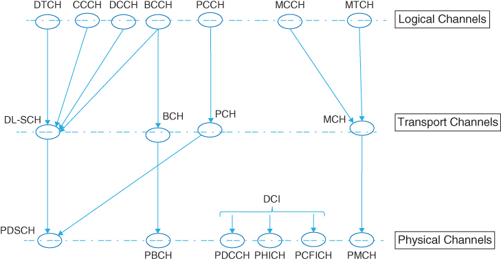
In the multicast/broadcast mode, we have a traffic logical channel known as the Multicast Traffic Channel (MTCH) and a control logical channel known as the Multicast Control Channel (MCCH). These are combined to form the transport channel known as the Multicast Channel (MCH). Finally, the PMCH is formed as the physical channel for the MBMS mode.
2.10.2 Function of Downlink Channels
The PDSCH carries downlink user data as transport blocks that are handed down from the MAC layer to the PHY. Usually, transport blocks are transmitted one at a time in each subframe, except in a particular case of MIMO known as spatial multiplexing, where one or two transport blocks can be transmitted per given subframe. Following adaptive modulation and coding, the modulated symbols are mapped on to multiple time–frequency resource grids, which are eventually mapped to multiple transmit antennas for transmission. The type of multi-antenna technique used in each subframe is also subject to adaptation based on channel conditions.
The use of adaptive modulation, coding, and MIMO in the LTE standard implies that in each subframe, depending on the channel quality observed at the mobile terminal, the base station needs to make decisions about the type of modulation scheme, coding rate, and MIMO mode. The measurements made in the terminal must feed back to the base station in order to help the scheduling decisions made there for the ensuing transmissions. At each subframe, the mobile terminal needs to be notified about the scheduling from the base station for each transmitted resource block. Among the information that must be communicated are the number of resource blocks allocated to a user, the transport block size, the type of modulation, the coding rate, and the type of MIMO mode used per each subframe.
In order to foster communication between the base station and the mobile terminal, a PDCCH is defined for each PDSCH channel. PDCCH primarily contains the scheduling decisions that each terminal requires in order to successfully receive, equalize, demodulate, and decode the data packets. Since PDCCH information must be read and decoded before decoding of PDSCH begins, in a downlink PDCCH occupies the first few OFDM symbols of each subframe. The exact number of OFDM symbols at the beginning of each subframe occupied by the PDCCH (typically one, two, three, or four) depends on various factors, including the bandwidth, the subframe index, and the use of unicast versus multicast service type.
The control information carried on the PDCCH is known as DCI. Depending on the format of the DCI, the number of resource elements (i.e., the number of OFDM symbols needed to carry them) varies. There are 10 different possible DCI formats specified by the LTE standard. The available DCI formats and their typical use cases are summarized in Table 2.7.
Table 2.7 LTE Downlink Control Information (DCI) formats and their use cases
| DCI format | Use case |
| 0 | Uplink scheduling assignment |
| 1 | Downlink scheduling for one PDSCH codeword in SISO and SIMO modes |
| 1A | Compact version of format 1 scheduling for one PDSCH codeword or dedicated preamble assignment to iniate random access |
| 1B | Very compact downlink scheduling for one PDSCH codeword used in MIMO mode number 6 |
| 1C | Very compact downlink scheduling for paging or system information |
| 1D | Compact downlink scheduling for one PDSCH codeword with MIMO precoding and power offset information necessary for multi-user MIMO |
| 2 | Downlink scheduling assignment for MIMO with closed-loop spatial multiplexing |
| 2A | Downlink scheduling assignment for MIMO with open-loop spatial multiplexing |
| 3 | Transmit Power Control (TPC) information for PUCCH and PUSCH with 2 bit power adjustment |
| 3A | Transmit power control (TPC) information for PUCCH and PUSCH with 1 bit power adjustment |
Each DCI format contains the following types of control information: resource allocation information, such as resource block size and resource assignment duration; transport information, such as multi-antenna configuration, modulation type, coding rate, and transport block payload size; and finally information related to the HARQ, including its process number, the redundancy version, and the indicator signaling availability of new data. For example, the content fields of DCI format 1 are summarized in Table 2.8.
Table 2.8 Content of the DCI format 1
| Field | Number of bits on PDCCH | Description |
| Resource allocation header | 1 | Indicates the selected resource allocation of either type 0 or type 1 |
| Resource block assignment | Depends on resource allocation type | Indicates resource blocks on PDSCH to be assigned to the terminal |
| Modulation and Coding Scheme (MCS) | 5 | Indicates the type of modulation and coding used, together with the transport block size and the number of resource blocks allocated |
| HARQ process number | 3 (FDD) 4 (TDD) | Indicates the HARQ ID used in asynchronous stop-and-wait protocol |
| New data indicator | 1 | Indicates whether the current packet is a new transmission or a retransmission |
| Redundancy version | 2 | Indicates the incremental redundancy state of the HARQ process |
| PUCCH TPC command | 2 | Indicates the transmit power control command for adaptation of transmit power on PUCCH |
| Downlink assignment index | 2 | (Only for TDD mode) Indicates the number of downlink subframes used for uplink ACK/NACK bundling |
The PCFICH is used to define the number of OFDM symbols that the DCI occupies in a subframe. The PCFICH information is mapped to specific resource elements belonging to the first OFDM symbol in each subframe. The possible values for PCFICH (one, two, three, or four) depend on the bandwidth, frame structure, and subframe index. For bandwidths larger than 1.4 MHz, PCFICH code can take up to three OFDM symbols. For 1.4 MHz bandwidth, since the number of resource blocks is quite small, PCFICH may need up to four symbols for control signaling.
Besides the PDCCH and PCFICH control channels, LTE defines another control channel known as the Physical HARQ Indicator Channel (PHICH). The PHICH contains information regarding the acknowledgment response for received packets in the uplink. Following the transmission of an uplink packet, the UE will receive an acknowledgment for that packet on a PHICH resource after a predetermined time delay. The duration of the PHICH is determined by higher layers. In the case of a normal duration, the PHICH is only found in the first OFDM symbol of a subframe; with extended duration, it is found in the first three subframes.
The PBCH carries the Master Information Block (MIB), which contains the basic PHY system information and cell-specific information during the cell search. After the mobile terminal correctly acquires the MIB, it can then read the downlink control and data channels and perform necessary operations to access the system. The MIB is transmitted on the PBCH over 40 ms periods, corresponding to four radio frames, with portions transmitted in the first subframe of every frame. The MIB contains four fields of information. The first two fields hold information regarding downlink system bandwidth and PHICH configuration. The downlink system bandwidth is communicated as one of six values for the number of resource blocks in downlink (6, 15, 25, 50, 75, or 100). As discussed earlier, these values for the number of resource blocks map directly to bandwidths of 1.4, 3, 5, 10, 15, and 20 MHz, respectively. The PHICH configuration field of the MIB specifies the duration and amount of the PHICH, as described earlier. The PBCH is always confined to the first four OFDM symbols found in the first slot of the first subframe of every radio frame. In frequency, the PBCH occupies 72 subcarriers centered on the DC subcarrier. Following a description of the physical signals, we can completely describe the content of the frame structures in the LTE standard.
2.10.3 Uplink Physical Channels
Table 2.9 summarizes the LTE uplink physical channels. The Physical Uplink Shared Channel (PUSCH) carries the user data transmitted from the user terminal. The Physical Random Access Channel (PRACH) is used for initial access of a UE to the network through transmission of random access preambles. The Physical Uplink Control Channel (PUCCH) carries the UCI, including scheduling requests (SRs), acknowledgments of transmission success or failure (ACKs/NACKs), and reports of downlink channel measurements including the Channel Quality Indicator (CQI), Precoding Matrix Information (PMI), and Rank Indication (RI).
Table 2.9 LTE uplink physical channels
| Uplink physical channel | Function |
| Physical Uplink Shared Channel (PUSCH) | Uplink user data traffic |
| Physical Uplink Control Channel (PUCCH) | Uplink Control Information (UCI) |
| Physical Random Access Channel (PRACH) | Initial access to network through random access preambles |
Figure 2.9 illustrates the relationship between logical, transport, and physical channels in the LTE uplink architecture. Starting with logical channels, we have a Dedicated Traffic Channel (DTCH) and two logical control channels, a Common Control Channel (CCCH), and a Dedicated Control Channel (DCCH). These three channels are combined to form the transport channel known as the Uplink Shared Channel (UL-SCH). Finally, the Physical Uplink Shared Channel (PUSCH) and the Physical Uplink Control Channel (PUCCH) are formed as the physical channels. The transport channel known as the Random Access Channel (RACH) is also mapped to the Physical Random Access Channel (PRACH).
Figure 2.9 Mapping LTE uplink logical, transport, and physical channels

2.10.4 Function of Uplink Channels
The PUCCH carries three types of control signaling information: ACK/NACK signals for downlink transmission, scheduling requests (SR) indicators, and feedback from the downlink channel information, including the CQI, the PMI, and the RI.
The feedback of the downlink channel information relates to MIMO modes in downlink. In order to ensure that the MIMO transmission schemes work correctly in downlink, each terminal must perform measurements on the quality of the radio link and report the channel characteristic to the base station. This essentially describes the channel quality functions of the UCI as contained in the PUCCH.
The CQI is an indicator of downlink mobile radio channel quality measures as taken by the UE and transmitted to the base station for use in subsequent scheduling. It allows the UE to propose to the base station a set of optimal modulation schemes and coding rates matched to the present radio link quality. There are 16 combinations of the modulation schemes and coding rates that are transmitted as CQI information. Higher CQI values stand for higher modulation orders and higher coding rates. Either a wideband CQI is used, which applies to all resource blocks forming the bandwidth, or else a subband CQI is used, which assigns a given CQI value to a certain number of resource blocks. The higher-layer configurations determine the rate, periodicity, or frequency of CQI measurements in the terminal.
The PMI is an indication of a preferred precoding matrix to be used in a base station for a given radio link. The PMI values represent precoding table indices for a two, four, or eight transmit antenna configuration. The RI signals the number of useful transmit antennas, estimated based on the channel quality and its effect on the correlations observed between adjacent receive antennas. In the following sections, we will describe MIMO modes of transmission in the LTE standard. From this, the roles of the CQI, PMI and RI indicators will become clear.
2.11 Physical Signals
A variety of physical signals, including reference and synchronization signals, are transmitted within the shared physical channel. Physical signals map to a specific resource element used by the PHY but do not carry information originating from higher layers. The details of LTE signals are presented next.
2.11.1 Reference Signals
Channel-dependent scheduling in the frequency domain is one of the most attractive features of the LTE standard. For example, in order to perform downlink scheduling that is aware of the actual channel quality, the mobile terminal must provide the base station with the Channel-State Information (CSI). The CSI may be obtained by measuring reference signals transmitted in the downlink. Reference signals are transmitted signals that are generated with synchronized sequence generators in the transmitter and the receiver. These signals are placed in specific resource elements in the time-frequency grid. LTE specifies several types of downlink and uplink reference signal, which are described next.
2.11.1.1 Downlink Reference Signals
Downlink reference signals support the channel estimation functionality needed to equalize and demodulate the control and data information. They are also instrumental in CSI measurements (such as RI, CQI, and PMI) needed for channel quality feedback. LTE specifies five types of reference signal for downlink transmission: Cell-Specific Reference Signals (CSR), Demodulation Reference Signal (DM-RS, otherwise known as UE-specific reference signal), Channel-State Information Reference Signal (CSI-RS), MBSFN reference signals, and positioning reference signals.
CSRs are common to all users in a cell and are transmitted in every downlink subframe. DM-RSs are used in downlink multi-user transmission modes 7, 8, or 9. As the name implies, they are intended for channel estimation performed by each individual mobile terminal in a cell. CSI-RSs were first introduced in LTE Release 10. Their main function is to alleviate the density problem associated with using CSRs for CSI measurements when more than eight antennas are in use. Therefore, the use of CSI-RSs is limited to the multi-user downlink transmission mode 9. MBSFN reference signals are used in the coherent demodulation employed in multicast/broadcast services. Finally, positioning reference signals, first introduced in LTE Release 9, help support measurements on multiple cells in order to estimate the position of a given terminal. In this section, we provide more detail on the first three types of reference signal enumerated here.
Cell-Specific Reference Signals
CRSs are transmitted in every downlink subframe and in every resource block in the frequency domain, and thus cover the entire cell bandwidth. The CRSs can be used by the terminal for channel estimation for coherent demodulation of any downlink physical channel except PMCH and PDSCH in the case of transmission modes 7, 8, or 9, corresponding to non-codebook-based precoding.
The CRSs can also be used by the terminal to acquire CSI. Finally, terminal measurements such as CQI, RI, and PMI performed on CRSs are used as the basis for cell selection and handover decisions.
UE-Specific Reference Signals
DM-RSs, or UE-specific reference signals, are only used in downlink transmission modes 7, 8, or 9, where CSRs are not used for channel estimation. DM-RSs were first introduced in LTE Release 8 in order to support a single layer. In LTE Release 9, up to two layers were supported. The extended specification introduced in Release 10 aimed to support up to eight simultaneous reference signals.
When only one DM-RS is used, we have 12 reference symbols within a pair of resource blocks. As will be discussed shortly, CSRs require spectral nulls or unused resource elements on all other antenna ports when a resource element on any given antenna is transmitting a reference signal. This is a major difference between CSR and DM-RS. When two DM-RSs are used on two antennas, all 12 reference symbols are transmitted on both antenna ports. The interference between the reference signals is mitigated by generating mutually orthogonal patterns for each pair of consecutive reference symbols.
CSI Reference Signals
CSI-RSs are designed for cases where we have between four and eight antennas. CSI-RSs were first introduced in LTE Release 10. They are designed to perform a complementary function to the DM-RS in LTE transmission mode 9. While the DM-RS supports channel estimation functionality, a CSI-RS acquires CSI. To reduce the overhead resulting from having two types of reference signal within the resource grid, the temporal resolution of CSI-RSs is reduced. This makes the system incapable of tracking rapid changes in the channel condition. Since CSI-RSs are only used with four to eight MIMO antenna configurations, and this configuration is only active with low mobility, the low temporal resolution of CSI-RSs does not pose a problem.
2.11.1.2 Uplink Reference Signals
There are two kinds of uplink reference signal in the LTE standard: the DM-RS and the Sounding Reference Signal (SRS). Both uplink reference signals are based on Zadoff–Chu sequences. Zadoff–Chu sequences are also used in generating downlink Primary Synchronization Signals (PSSs) and uplink preambles. Reference signals for different UEs are derived from different cyclic shift parameters of the base sequence.
Demodulation Reference Signals
DM-RSs are transmitted by UE as part of the uplink resource grid. They are used by the base station receiver to equalize and demodulate the uplink control (PUCCH) and data (PUSCH) information. In the case of PUSCH, when a normal cyclic prefix is used DSR signals are located on the fourth OFDM symbol in each 0.5 ms slot and extend across all the resource blocks. In the case of PUCCH, the location of DSR will depend on the format of the control channel.
Sounding Reference Signals
SRSs are transmitted on the uplink in order to enable the base station to estimate the uplink channel response at different frequencies. These channel-state estimates may be used for uplink channel-dependent scheduling. This means the scheduler can allocate user data to portions of the uplink bandwidth where the channel responses are favorable. SRS transmissions have other applications, such as timing estimation and control of downlink channel conditions when downlink and uplink channels are reciprocal or identical, as is the case in the TDD mode.
2.11.2 Synchronization Signals
In addition to reference signals, LTE also defines synchronization signals. Downlink synchronization signals are used in a variety of procedures, including the detection of frame boundaries, determination of the number of antennas, initial cell search, neighbor cell search, and handover. Two synchronization signals are available in the LTE: the Primary Synchronization Signal (PSS) and the Secondary Synchronization Signal (SSS).
Both the PSS and the SSS are transmitted as 72 subcarriers located around the DC subcarrier. However, their placement in FDD mode differs from that in TDD mode. In an FDD frame, they are positioned in subframes 0 and 5, next to each other. In a TDD frame, they are not placed close together. The SSS is placed in the last symbols of subframes 0 and 5 and the PSS is placed as the first OFDM symbols of the ensuing special subframe.
Synchronization signals are related to the PHY cell identity. There are 504 cell identities defined in the LTE, organized into 168 groups, each of which contains three unique identities. The PSS carries the unique identities 0, 1, or 2, whereas the SSS carries the group identity with values 0–167.
2.12 Downlink Frame Structures
LTE specifies two downlink frame structures. A type 1 frame applies to an FDD deployment and a type 2 frame is used for a TDD deployment. Each frame is composed of 10 subframes and each subframe is characterized by the time–frequency resource grid. We have identified the three components of a resource grid: user data, control channels and reference, and synchronization signals. Now we can explain how and where each of these components is placed as the LTE resource grid is populated per subframe before OFDM symbols are generated and transmitted. Without a loss in generality, in this book we focus on FDD frame structures and type 1 frames.
Figure 2.10 shows the type 1 radio frame structure. The duration of each frame is 10 ms, composed of ten 1 ms subframes denoted by indices ranging from 0 to 9. Each subframe is subdivided into two slots of 0.5 ms duration. Each slot is composed of seven or six OFDM, depending on whether a normal or an extended cyclic prefix is used. The DCI is placed within the first slot of each subframe. The DCI carries the content of the PDCCH, PCFICH, and PHICH, and together they occupy up to the first three OFDM symbols in each subframe. This region is also known as the L1/L2 control region, since it contains information that is transferred to layer 1 (PHY) from layer 2 (the MAC layer).
Figure 2.10 Downlink FDD subframe structure

The PBCH containing the MIB is located within subframe 0 and the PSS and SSS are located within subframes 0 and 5. The PBCH channel and both the PSS and SSS signals are placed within the six resource blocks centered on the DC subcarrier. In addition, CSRs are placed throughout each resource block in each subframe with a specific pattern of time and frequency separations. The pattern of placement for the CSR signals depends on the MIMO mode and the number of antennas in use, as will be discussed shortly. The rest of the resource elements in each subframe are allocated to user traffic data.
2.13 Uplink Frame Structures
The uplink subframe structure is in some ways similar to that for the downlink. It is composed of 1 ms subframes divided into two 0.5 ms slots. Each slot is composed of either seven or six SC-FDM symbols, depending on whether a normal or an extended cyclic prefix is used. The inner-band resource blocks are reserved for data resource elements (PUSCH) in order to reduce out-of-band emissions. Different users are assigned different resource blocks, a fact that ensures orthogonality among users in the same cell. Data transmission can hop at the slot boundary to provide frequency diversity. Control resources (PUCCH) are then placed at the edge of the carrier band, with interslot hopping providing frequency diversity. The reference signals necessary for data demodulation are interspersed throughout the data and control channels. Figure 2.11 illustrates an uplink frame structure.
Figure 2.11 Uplink frame structure

2.14 MIMO
The LTE and LTE-Advanced standards achieve their maximum data rates in part due to their incorporation of many multi-antenna or MIMO techniques. LTE standards perfectly combine the OFDM transmission structure with various MIMO methodologies. As such, LTE standards represent a MIMO-OFDM system. As we saw earlier, the OFDM transmission scheme in each antenna constructs the resource grid, generates the OFDM symbols, and transmits. In a MIMO-OFDM system, this process is repeated for multiple transmit antennas. Following transmission of OFDM symbols associated with multiple resource grids on multiple transmit antennas, at each receive antenna the OFDM symbols of all transmitted antennas are combined. The objective of a MIMO receiver is thus to separate the combined signals, and based on the received estimates of resource elements, to resolve each resource element transmitted on each of the transmit antennas.
Multi-antenna techniques rely on transmission by more than one antenna at the receiver or the transmitter, in combination with advanced signal processing. Although multi-antenna techniques raise the computational complexity of the implementation, they can be used to achieve improved system performance, including improved system capacity (in other words, more users per cell), and improved coverage or the possibility of transmitting over larger cells. The availability of multiple antennas at the transmitter or the receiver can be utilized in different ways to achieve different aims.
2.14.1 Receive Diversity
The simplest and most common multi-antenna configuration is the use of multiple antennas at the receiver side (Figure 2.12). This is often referred to as receive diversity. The most important algorithm used in receive diversity is known as Maximum-Ratio Combining (MRC). It is used within mode 1 of transmission in the LTE standard, which is based on single-antenna transmission. This mode is also known as SISO (Single Input Single Output) where only one receiver antenna is deployed or SIMO (Single Input Multiple Output) where multiple receive antennas are used. Two types of combining method can be used at the receiver: MRC and Selection Combining (SC) 2. In MRC, we combine the multiple received signals (usually by averaging them) to find the most likely estimate of the transmitted signal. In SC, only the received signal with the highest SNR is used to estimate the transmitted signal.
Figure 2.12 MIMO receive diversity

MRC is a particularly good MIMO technique when, in a fading channel, the number of interfering signals is large and all signals exhibit rather equal strengths. As such, MRC works best in transmission over a flat-fading channel. In practice, most wideband channels, as specified in LTE, are subject to time dispersion, resulting in a frequency-selective fading response. To counteract the effects of frequency-selective coding, we must perform linear equalization, and in order to make this more efficient it should be done in the frequency domain. The MIMO techniques that handle these types of degradation best are discussed next.
2.14.2 Transmit Diversity
Transmit diversity exploits multiple antennas at the transmitter side to introduce diversity by transmitting redundant versions of the same signal on multiple antennas. This type of MIMO technique is usually referred to as Space–Time Block Coding (STBC). In STBC modulation, symbols are mapped in the time and space (transmit antenna) domains to capture the diversity offered by the use of multiple transmit antennas.
Space–Frequency Block Coding (SFBC) is a technique closely related to STBC that is selected as the transmit diversity technique in the LTE standard. The main difference between the two techniques is that in SFBC the encoding is done in the antenna (space) and frequency domains rather than in the antenna (space) and time domains, as is the case for STBC. A block diagram of SFBC is given in Figure 2.13.
Figure 2.13 MIMO Space–Frequency Block Coding

In LTE, the second transmission mode is based on transmit diversity. SFBC and Frequency-Switched Transmit Diversity (FSTD) are used for two- and four-antenna transmission, respectively. Transmit diversity does not help with any boost in data rate; it only contributes to the increased robustness against channel fading and improves the link quality. Other MIMO modes – specifically, spatial multiplexing – contribute directly to the increased data rate in the LTE standard.
2.14.3 Spatial Multiplexing
In spatial multiplexing, completely independent streams of data are transmitted simultaneously over each transmit antenna. The use of spatial multiplexing enables a system to increase its data proportionally to the number of transmit antenna ports. At the same time, and at the same subcarrier in frequency, different modulated symbols are transmitted over different antennas. This means spatial multiplexing can directly increase the bandwidth efficiency and result in a system with high bandwidth utilization. The benefits of spatial multiplexing can be realized only if transmissions over different antennas are not correlated. This is where the multipath fading nature of a communication link actually helps the performance. Since multipath fading can decorrelate the received signals at each receive antenna port, spatial multiplexing transmitted over a multipath fading channel can actually enhance the performance.
All the benefits of spatial multiplexing can be realized only if a system of linear equations describing the relationship between transmit and receive antennas can be solved. Figure 2.14 illustrates the spatial multiplexing for a 2 × 2 antenna configuration. At each subcarrier, the symbols s1 and s2 are transmitted over two transmit antennas. The received symbols at the same subcarrier r1 and r2 may be considered the result of a linear combination of s1 and s2 weighted by the channel matrix H with the addition of AWGN (Additive White Gaussian Noise) n1 and n2. The resulting MIMO equation can be expressed as:
2.5 ![]()
where the MIMO channel matrix H contains the channel frequency responses at each subcarrier ![]() for any combination of transmit antenna i and receive antenna j. In a matrix notation generalized for any number of transmit and receive antennas, the equation becomes:
for any combination of transmit antenna i and receive antenna j. In a matrix notation generalized for any number of transmit and receive antennas, the equation becomes:
2.6 ![]()
where ![]() represents the M-dimensional vector of transmitted signals at the transmitter side:
represents the M-dimensional vector of transmitted signals at the transmitter side: ![]() and the vectors
and the vectors ![]() and
and ![]() are N-dimensional vectors representing the received signals and corresponding noise signals:
are N-dimensional vectors representing the received signals and corresponding noise signals: ![]() ;
; ![]() .
.
Figure 2.14 MIMO spatial multiplexing

When all the elements of vector ![]() belong to a single user, the data streams of this single user are multiplexed on to various antennas. This is referred to as a Single-User Multiple Input Multiple Output (SU-MIMO) system. When data streams of different users are multiplexed on to different antennas, the resulting system is known as a Multi-User Multiple Input Multiple Output (MU-MIMO) system. SU-MIMO systems substantially increase the data rate for a given user and MU-MIMO systems increase the overall capacity of a cell to handle multiple calls.
belong to a single user, the data streams of this single user are multiplexed on to various antennas. This is referred to as a Single-User Multiple Input Multiple Output (SU-MIMO) system. When data streams of different users are multiplexed on to different antennas, the resulting system is known as a Multi-User Multiple Input Multiple Output (MU-MIMO) system. SU-MIMO systems substantially increase the data rate for a given user and MU-MIMO systems increase the overall capacity of a cell to handle multiple calls.
One of the most fundamental questions regarding the operation of a spatial multiplexing system is whether or not the corresponding MIMO equation can be solved and whether it has a unique solution. This question relates to the singularity of the corresponding MIMO channel matrix and whether or not it can be inverted. When the received signals on many receive antennas are correlated, the channel matrix H may have rows or columns that are linearly dependent. In that case, the resulting channel matrix will have a rank less than its dimension and the matrix will be deemed non-invertible. Therefore, rank estimation is necessary for the spatial multiplexing since it determines whether it is possible to perform the spatial multiplexing operations under any given channel condition. The actual value of the rank of the matrix indicates the maximum number of transmit antennas that can be successfully multiplexed. In LTE terminology, the rank is known as the number of layers in the spatial multiplexing modes of MIMO.
In closed-loop MIMO operations, the rank of the channel matrix is computed by the mobile and transmitted to the base station via the uplink control channels. If the channel is deemed to have less than a full rank, only a reduced number of independent data streams can take part in spatial multiplexing in the upcoming downlink transmissions. This feature, known as rank adaptation, is part of the adaptive MIMO schemes and complements other adaptive features of the LTE standard.
2.14.4 Beam Forming
In beam forming, multiple transmit antennas can be used to shape the overall antenna radiation pattern (or the beam) in order to maximize the overall antenna gain in the direction of the mobile terminal. This type of beam forming provides the basis of downlink MIMO transmission mode 7.
The use of beam-forming techniques can lead to an increase in the signal power at the receiver proportional to the number of transmit antennas. Typically, beam forming relies on the use of an antenna array of at least eight antenna elements 3. Beam forming is then implemented by applying different complex-valued gains (otherwise known as weights) to different elements of the antenna array. The overall transmission beam can then be steered in different directions by applying different phase shifts to the signals on the different antennas, as illustrated in Figure 2.15.
Figure 2.15 MIMO beam forming

The LTE standard specifies neither the number of antennas in the antenna array nor the algorithms that are to be used in adjusting the complex-valued gains applied to each array element. The LTE specification refers to an antenna port 5, which represents the virtual antenna port created by the use of beam-forming techniques. UE-specific reference signals are used for channel estimation in beam forming MIMO mode 7. Higher layers call the use of UE-specific reference signals to the mobile terminal. Since mutually orthogonal reference signals are generated scheduled on the same pairs of resource blocks, different UEs (mobile terminals) can resolve their allocated reference signals and use them for equalization and demodulation.
2.14.5 Cyclic Delay Diversity
Cyclic Delay Diversity (CDD) is another form of diversity that is used in the LTE standard in conjunction with open-loop spatial multiplexing. CDD applies cyclic shifts to vectors or blocks of signal transmitted at any given time on different antennas. This is an effect analogous to the application of a known precoder. As such, CDD fits very well with block-based transmission schemes such as OFDM and SC-FDM. In the case of OFDM transmission, for example, a cyclic shift of the time domain corresponds to a frequency-dependent phase shift in the frequency domain. Since the phase shift in frequency – that is, the precoder matrix – is known and predictable, CDD is used in open-loop spatial multiplexing and in high-mobility scenarios where closed-loop feedback of an optimal precoder matrix is not desirable. The net effect of applying CDD is the introduction of artificial frequency diversity as experienced by the receiver. We can easily extend CDD to more than two transmit antennas, with different cyclic shifts for each.
2.15 MIMO Modes
Table 2.10 summarizes the LTE transmission modes and the associated multi-antenna transmission schemes. Mode 1 uses receive diversity and mode 2 is based on transmit diversity. Modes 3 and 4 are single-user implementations of spatial multiplexing based on open-loop and closed-loop precoding, respectively. Mode 3 also uses CDD (discussed earlier).
Table 2.10 LTE transmission modes and their associated multi-antenna transmission schemes
| LTE transmission modes | |
| Mode 1 | Single-antenna transmission |
| Mode 2 | Transmit diversity |
| Mode 3 | Open-loop codebook-based precoding |
| Mode 4 | Closed-loop codebook-based precoding |
| Mode 5 | Multi-user MIMO version of transmission mode 4 |
| Mode 6 | Single-layer special case of closed-loop codebook-based precoding |
| Mode 7 | Release 8 non-codebook-based precoding supporting only a single layer, based on beam forming |
| Mode 8 | Release 9 non-codebook-based precoding supporting up to two layers |
| Mode 9 | Release 10 non-codebook-based precoding supporting up to eight layers |
LTE mode 5 specifies a very simple implementation of multi-user MIMO based on mode 4 with the maximum number of layers set to one. Mode 6 features beam forming and a special case of mode 4 where the number of layers is set to two. LTE modes 7–9 implement versions of spatial multiplexing without the use of codebooks, with a number of layers of 1, up to 2, and 4–8, respectively. The LTE-Advanced (Release 10) introduced major enhancements to downlink MU-MIMO by introducing modes 8 and 9. For example, mode 9 supports eight transmit antennas for transmissions of up to eight layers. These advances result directly from the introduction of new reference signals (CSI-RS and DM-RS), enabling a non-codebook-based precoding and thus adopting a lower-overhead double-codebook structure 4.
2.16 PHY Processing
In order to understand the LTE PHY, we have to specify the following sequence of operations. First, describe channel coding, scrambling, and modulation resulting in modulated symbols, then describe the steps in mapping the modulated signals to the resource grid, including mapping the user data, the reference signals, and the control data. Then, specify the MIMO modes that enable multiple antenna transmissions. The different MIMO algorithms involve specifying layer mapping, which describes how many transmit antennas are used in every frame and what precoding transformation is applied to the modulated bits before they are mapped to the resource grids of all transmit antennas.
2.17 Downlink Processing
The chain of signal processing operations performed in the transmitter can be summarized as the combination of transport block processing and physical channel processing. The processing stack is completely specified in 3GPP documents describing the multiplexing and channel coding 5 and physical channels and modulation 3. The baseband signal processing chain applied to the combination of DLSCH and PDSCH can be summarized as follows:
- Transport-block CRC (Cyclic Redundancy Check) attachment
- Code-block segmentation and code-block CRC attachment
- Turbo coding based on a one-third rate
- Rate matching to handle any requested coding rates
- Code-block concatenation to generate codewords
- Scrambling of coded bits in each of the codewords to be transmitted on a physical channel
- Modulation of scrambled bits to generate complex-valued modulation symbols
- Mapping of the complex-valued modulation symbols on to one or several transmission layers
- Precoding of the complex-valued modulation symbols on each layer for transmission on the antenna ports
- Mapping of complex-valued modulation symbols for each antenna port to resource elements
- Generation of complex-valued time-domain OFDM signal for each antenna port.
Figure 2.16 illustrates the combination of the signal processing applied to transport blocks delivered to the PHY from the MAC layer until the OFDM signal is transferred to antennas for transmission.
Figure 2.16 Signal processing chain of downlink DLSCH and PDSCH

Each of the components of LTE downlink transmission is described in detail in Chapters 4–7. In Chapter 4, we will elaborate on DLSCH processing and on scrambling and modulation mapper functionality. In Chapter 5, we will detail the OFDM multicarrier transmission scheme used in downlink. In Chapter 6, we will review details regarding various MIMO implementations of the standard. In Chapter 7, we will describe the link adaptation functionalities that use various control channels for dynamic scheduling of resources according to the channel conditions.
2.18 Uplink Processing
The chain of signal processing operations applied to the combination of ULSCH and PUSCH is summarized as follows:
- Transport-block CRC attachment
- Code-block segmentation and code-block CRC attachment
- Turbo coding based on a one-third rate
- Rate matching to handle any requested coding rates
- Code-block concatenation to generate codewords
- Scrambling
- Modulation of scrambled bits to generate complex-valued symbols
- Mapping of modulation symbols on to one or several transmission layers
- DCT transform precoding to generate complex-valued symbols
- Precoding of the complex-valued symbols
- Mapping of precoded symbols to resource elements
- Generation of a time-domain SC-FDM signal for each antenna port.
Figure 2.17 illustrates the combination of the signal processing applied to transport blocks delivered to the PHY until the SC-FDM signal is transferred to antennas for transmission. The processing stack is also fully specified in 3GPP documents describing the multiplexing and channel coding 5 and physical channels and modulation 3.
Figure 2.17 Signal processing chain of downlink ULSCH and PUSCH

In this section, we will describe two distinguishing components of uplink transmission: SC-FDM based on DFT-precoded OFDM and MU-MIMO.
2.18.1 SC-FDM
In LTE, a special precoding, based on the application of DFT to modulated symbols, is used to generate the SC-FDM signal in the frequency domain. Note that SC-FDM signal generation is almost identical to that of OFDM, with the exception that an additional M-point DFT is introduced. Usually, computing the DFT is less computationally efficient than computing the FFT. However, we can find efficient implementations for certain DFTs whose sizes are of prime lengths. This is the reason why LTE specifies the M-point DFT sizes as multiples of two, three, or five (all prime numbers).
In uplink transmission, following coding, scrambling, and modulation and prior to resource element mapping, a DFT-based precoder is applied to the modulated symbols of each layer. The DFT-transformed symbols are then mapped to frequency subcarriers prior to the IFFT operation and cyclic prefix insertion, which finally leads to SC-FDM signal generation. The data symbols of any individual user transmitted as a SC-FDM symbol must be either contiguous or evenly spaced in the resource grid.
Localized mapping of DF-precoded symbols within the resource grid means that the entire allocation is contiguous in frequency. This results in acceptable channel-estimation performance, since the pilots are contiguous and simple interpolating techniques can be used in channel estimation. Furthermore, multiplexing of different users in the spectrum based on a contiguous resource block pattern is quite easy. Distributed mapping, on the other hand, means that the allocated bandwidth is evenly distributed in frequency. This type of mapping delivers a good measure of frequency diversity. However, since it also distributes the pilots, the resulting channel estimation performance will suffer. Multiplexing all the users together in the spectrum will also be more difficult in distributed mapping. As such, distributed or localized frequency allocations represent typical tradeoffs between frequency diversity and performance.
2.18.2 MU-MIMO
In mobile systems, the number of receive antennas N at the mobile terminal is often smaller than the number of transmit antennas M at the base station. Since the capacity gain offered by MIMO systems is scaled by the parameter ![]() , the capacity gain of SU-MIMO is limited by the number of receive antennas at the receiver (N) 4.
, the capacity gain of SU-MIMO is limited by the number of receive antennas at the receiver (N) 4.
In downlink transmission, this problem is addressed by MU-MIMO techniques, offered as transmission modes 7–9. In uplink, however, the LTE Release 8 only supports transmissions over one transmit antenna at the mobile terminal at a time, although multiple antennas may be present. This choice was motivated by an attempt to minimize the cost, power, and complexity of mobile hardware.
Antenna selection can be used to select one from among many transmit antennas at any time. In this case, the selection of the mobile transmit antenna can be either handled and signaled by the base station or locally managed by the mobile terminal. Uplink MU-MIMO can be viewed as a MIMO system where, different users transmit their streams on the same resource blocks while each transmitting on a single antenna in their mobile units.
Figure 2.18 shows a block diagram of such an uplink MU-MIMO scenario. In this example, we form a bunch of MU-MIMO pairs by pairing together transmissions from couples of mobile units. The base station schedules the uplink transmission for each UE within the MU-MIMO pair in the same subframe and on the same resource blocks. Depending on the number of resource blocks available in the system bandwidth, we can schedule multiple MU-MIMO pairs simultaneously. The pairing can change in time based on such considerations as power control, individual channel quality, and interference profile. Although in our example we showed two paired users, the combination of DM-RS and CSI-RS reference signals in LTE-Advanced allows us to share up to eight mobile terminals in MU-MIMO that share the same resource blocks. For more information on MU-MIMO, the reader is referred to 4.
Figure 2.18 Uplink MU-MIMO

2.19 Chapter Summary
In this chapter we studied the PHY specifications of the LTE standards. We focused on identifying an adequate set of elements of the PHY model necessary for a deeper understanding of this subject. First, we examined the air interface of the standard, detailing its frequency bands, bandwidths, time framing, and time–frequency structure. We then elaborated on the multicarrier schemes of the standard: OFDM for downlink transmission and SC-FDM for uplink transmission. We identified the constituents of the OFDM resource grid, which is fundamental to understanding the PHY modeling. We also discussed the frame structures in uplink and downlink.
We then covered the physical channels and physical signals used in both uplink and downlink transmissions. We also provided an introduction to the MIMO schemes used in the standard, which completely specify various transmission modes. Finally, we summarized the sequence of operations performed in downlink and uplink transmissions. We have left the details regarding modeling of the processing chain in MATLAB for Chapters 4–7.
References
[1] Ghosh, A. and Ratasuk, R. (2011) Essentials of LTE and LTE-A, Cambridge University Press, Cambridge.
[2] Dahlman, E., Parkvall, S. and Sköld, J. (2011) 4G LTE/LTE-Advanced for Mobile Broadband, Elsevier.
[3] 3GPP (2011) Evolved Universal Terrestrial Radio Access (E-UTRA), , Physical Channels and Modulation Version 10.0.0. TS 36.211, January 2011.
[4] C. Lim, T. Yoo, B. Clerckx, B. Lee, B. Shim, Recent trend of multiuser MIMO in LTE-advanced, IEEE Magazine, 51, 3, 127–136, 2013.
[5] 3GPP (2011) Evolved Universal Terrestrial Radio Access (E-UTRA), Multiplexing and Channel Coding. TS 36.212.