
CHAPTER 12
Editing, Evaluating, and Troubleshooting
IN THIS CHAPTER
Using Rollback to look at the results of the design tree
Reordering features in the design tree
Reordering all features as a folder
Selecting items using the Flyout FeatureManager
Summarizing best practice suggestions for modeling parts
Applying evaluation techniques to plastic parts and complex shapes
Diagnosing errors
Editing and evaluation techniques tutorial
When you use CAD programs, you typically create a part once but edit it many times. Design for change is at the core of most of the modeling work that you will do in SolidWorks, and deletion is not an editing option.
The initial stages of modeling are the most crucial. This is when you set up parametric relations between the features and sketches that form the foundation for an assembly or complex part. For this reason, editing often quickly turns into repair. Granted, some changes are simply unavoidable, but a thorough knowledge of editing — and repairing — can help you to understand the how, what, and why of modeling best practice.
This chapter starts with some very basic concepts of editing, which you may have picked up if you have been reading this book from the beginning. It also contains a summary of part modeling best practice techniques and a set of model evaluation tools that can help you evaluate the manufacturability and aesthetic properties of parts. I have included these evaluation tools in a chapter on editing because the create-evaluate-edit-evaluate cycle is one of the most familiar in modeling and design practice.
Using Rollback
Rolling back a model simply means looking at the results of the design tree up to a certain point in the model history. In SolidWorks, you can actually change history — that is, you can change the order in which operations are completed. The order in which you create features is recorded, and if you change this order, you get a different geometric result.
You can use several methods to put the model in this rolled-back state:
- Dragging the Rollback bar with the cursor.
- Right mouse button (RMB) clicking and selecting one of the Rollback options.
- Editing a feature other than the last one in the design tree. (SolidWorks rolls back the model automatically.)
- Choose Tools
 Options FeatureManager Arrow key navigation to control the Rollback bar with the arrow keys.
 - Saving the model while editing a feature or sketch, and then exiting the model. When the part is opened again, it is rolled back to the location of the sketch that was being edited.
- Pressing Esc during a long model rebuild. This method is supposed to roll you back to the last feature that was rebuilt when you pressed Esc; however, in practice, I have rarely seen it do this, and it usually rebuilds the entire model anyway.
Using the Rollback bar
The Rollback bar, which typically appears at the bottom of the FeatureManager in SolidWorks part documents, enables you to put the part into almost any state in the model history. This is not the same as the Undo command, but is the equivalent of going back in time to change your actions, and then replaying everything that you did after that point. Figure 12.1 shows the Rollback bar in use. Notice how the cursor changes into a hand icon when you move it over the bar.
FIGURE 12.1 Using the Rollback bar
Understanding consumed features
When you use a sketch for a feature such as a Sketch Driven Pattern, the sketch is left in the design tree, in the place where it was created. However, most other features, such as extrudes, consume the sketch, meaning that the sketch disappears from its normal order in the FeatureManager and appears indented under the feature that was created from it. Consumed sketches are sometimes also referred to as absorbed sketches.
Examining the parent-child relationship
In genealogical family tree diagrams, the parent-child relationship is represented with the parent at the top, and the children branched below the parent. In SolidWorks, parent-child relationships are tracked differently. Figure 12.2 shows the difference between a genealogical family tree and the SolidWorks design tree.
FIGURE 12.2 Different interpretations of the structure of parent-child relationships

You can display the parent-child relations between SolidWorks features, as shown in Figure 12.2, by right-clicking on any feature and selecting Parent/Child. This helps you determine relationships before you make any edits or deletions because you can see which features will be removed or go dangling (lose their references).
When SolidWorks puts the child feature at the top, it is, in effect, turning the relationship upside down. In the SolidWorks FeatureManager, the earlier point in history is at the top of the tree, but the children are listed before the parents. The SolidWorks method stresses the importance of solid features over other types of sketch or curve features.
For example, you create an extrude from a sketch, and, therefore, the sketch exists before the extrude in the FeatureManager. However, when you create the extrude, SolidWorks places the sketch underneath the extrude. This restructuring can become more apparent when a sketch (for example, Sketch1) is created early in the part history, and then not used to create a feature (for example, Extrude5) until much later. If you roll down the FeatureManager feature by feature, you arrive at a point at the end of the design tree where Extrude5 appears and Sketch1 suddenly moves from its location at the top of the tree to under Extrude5 at the bottom of the tree.
This scenario may cause a situation where many sketches and other features that are created between Sketch1 and Extrude5 are dependent on Sketch1, but where Sketch1 suddenly appears after all these other features. This can be difficult to understand but is key to effectively editing parts, especially parts that someone else created.
The main point here is that SolidWorks displays many relationships upside down. You need to understand how to navigate and manage these history-bound relationships.
One way to get around difficulties in understanding the chronological order of features when compared against the relationship order of features is to roll back a model tree item by item. This can help you sort through the issues. Also remember that from SolidWorks's point of view, the solid feature is the most important item in the tree and is what the rest of the items in the tree support. SolidWorks has made the solid features easily visible and accessible in the tree.
Rolling back features with multiple parents
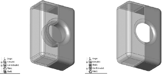
Take an example such as a loft with guide curves. If you create the guide curves first, and then you create the loft profiles by referencing the guide curves, the loft automatically reorders these sketches when they display under the loft feature such that the profiles are listed in the order in which they were selected, followed by the guide curves in the order in which they were selected. This is shown in Figure 12.3. This restructuring can be confusing if you want to go back and edit any of the relationships between the sketches. You can find this example on the DVD with the filename Chapter 12 Loftwgc.sldprt.
FIGURE 12.3 Multiple parents and sketch reordering

In this example, the two guide curves were created as part of a single sketch, and the SelectionManager was used to select them as individual open curves. This is why the Guide Curves sketch is represented with the contour symbol rather than a regular sketch symbol.
Viewing consumed features in their original order
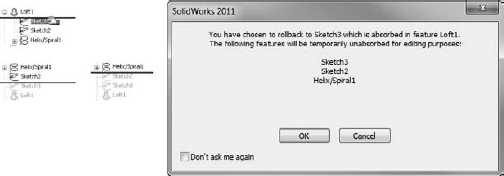
If you want to view consumed sketches in their original order — for example, the sketches in the loft feature in Figure 12.3 — you must first expand the feature by clicking the plus (+) symbol next to it so that you can see the consumed sketches, and then roll back between the feature and the first sketch. At this point, a warning message appears, stating that the sketches will be temporarily unabsorbed during editing. You can then move the Rollback bar again to show the sketches.
This maneuver can become complicated when you have two sketches absorbed by a projected curve, the projected curve absorbed by a composite curve, and the composite curve absorbed by a sweep feature. To isolate the original projected sketches, you need to repeat the technique with the Rollback bar as described earlier, once for each parent/child relationship. This is shown in Figure 12.4, and the steps to accomplish it are as follows.
FIGURE 12.4 Rollback of nested, absorbed features

To view consumed sketches in their original order, follow these steps:
- Expand the sweep.
- Roll back between the sweep and the profile sketch.
- Answer the prompt that appears.
- Roll down so that you can see the unabsorbed sketches and curves.
- Expand the composite curve.
- Roll back to just after the composite curve.
- Roll back so that you can see the contents of the composite curve.
- Expand the projected curve.
- Roll back to just after the projected curve.
- Roll back so that you can see the contents of the projected curve.
Using other Rollback techniques
The Rollback feature is located on the RMB menu. Simply right-click a feature and select either Rollback or Roll to Previous. If you are already rolled back and you right-click below the Rollback bar, you can access additional options to Roll Forward and Roll to End.
Editing any feature other than the last feature also serves to roll back the model while you are in Edit mode. As soon as you rebuild the feature or sketch, SolidWorks rebuilds the entire design tree.
The Tools ![]() Options
Options ![]() View setting for Arrow Key Navigation enables you to use the up- and down-arrow keys to manipulate the Rollback bar. Under normal circumstances, the arrow keys control the view orientation, but after you have moved the Rollback bar once using the cursor, the up- and down-arrow keys control the Rollback bar. The left- and right-arrow keys have no effect on the Rollback bar.
View setting for Arrow Key Navigation enables you to use the up- and down-arrow keys to manipulate the Rollback bar. Under normal circumstances, the arrow keys control the view orientation, but after you have moved the Rollback bar once using the cursor, the up- and down-arrow keys control the Rollback bar. The left- and right-arrow keys have no effect on the Rollback bar.
Caution
The one situation where this technique does not work as expected is when you are working on a part in the context of the assembly, with the design tree rolled back. The down arrow simply causes the Rollback bar to roll immediately to the end of the design tree.
Reordering Features
The ability to reorder features is one that offers SolidWorks users control over the modeling process and its outcome. Without this capability, editing would not be one of the strengths of the software. As you already know, feature order can make a difference in the final shape of a part. For example, this order:
Extrude
Cut
Fillet
Shell
gives you a very different part from this order:
Extrude
Shell
Cut
Fillet
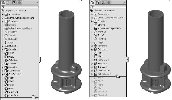
The results of these different orders are shown in Figure 12.5. (The part is split and partially transparent for demonstration purposes only.) You can view this part on the DVD; it is filename Chapter 12 Reorder.sldprt.
FIGURE 12.5 Parts that use a different feature order
On the part in the example shown in Figure 12.5, it is fairly simple to reorder the Shell feature by dragging it up the design tree. As a result, the well created by the Cut feature is not shelled around (to create a tube) if the cut comes after the shell. Also, notice the effect of applying the fillets after the shell rather than before it. The corners inside the box are sharp, while the outside corners have been filleted. When you apply the fillet before the shell, fillets that have a radius larger than the shell thickness are transferred to the inside of the shell.
![]() When you are reordering the features, a symbol may appear on the reorder cursor that says that you cannot reorder the selected feature to the location you want. In this case, you may want to select the Parent/Child option from the RMB menu to investigate. Sketch relationships, feature end conditions, and faces or edges selected for features such shell, patterns, and mirror can cause relationships that prevent reordering.
When you are reordering the features, a symbol may appear on the reorder cursor that says that you cannot reorder the selected feature to the location you want. In this case, you may want to select the Parent/Child option from the RMB menu to investigate. Sketch relationships, feature end conditions, and faces or edges selected for features such shell, patterns, and mirror can cause relationships that prevent reordering.
If two adjacent features are to swap places, it generally does not matter whether you move one feature up the design tree or you move the other one down. However, there are isolated situations that are usually created by the nested, absorbed features discussed earlier, where one feature cannot go in one direction, but the other feature can go in the opposite direction, achieving the exact same result. If you run into a situation where you cannot reorder a feature in one direction even though it appears you should be able to, try moving another feature the other direction.
While this behavior may appear to be a bug, it is more likely just a product of parent/child relationships hidden by the way SolidWorks reorders consumed parent sketches and other types of features. If you were able to stretch the FeatureManager out into a straight line from earliest to latest, the difficulties in reordering would become apparent.
Reordering Folders
There are times when, regardless of which features you choose to move and which direction you choose to move them in, you are faced with the task of moving many features. This can be time-consuming and tedious, not to mention have the potential to introduce errors. To simplify this process, you can put all the features to be moved into a single folder, and then reorder the folder. Keep in mind that the items in the folder need to be a continuous list (you cannot skip features), and you can only reorder the folder if each individual feature within the folder can be reordered.
Best Practice
Folders are frequently used for groups of features that go together and that may be suppressed or unsuppressed in groups. You can also use folders in assemblies. Folders are frequently used to group cosmetic fillet features that are often found at the end of design trees for plastic parts or for groups of whole features.
To create a folder, right-click a feature, or a selected group of features, and select Add to New Folder. Folders should be renamed with a name that helps identify their contents. You can reorder folders in the same way as individual features. When you delete a folder, the contents are removed from the folder and put back into the main tree; they are not deleted.
You can add or remove features to or from the folders by dragging them in or out. If a folder is the last item in the FeatureManager, the next feature that is created is not put into the folder; you must place it in the folder manually. You cannot drag features out of a folder and place them immediately after it, because they will just go back into the folder. If you want to pull a feature out of a folder and place it after the folder, there must be another feature between the feature that you are moving and the folder. However, you can pull a feature out of the folder and place it just before the folder.
Using the Flyout and Detachable FeatureManagers
The Flyout FeatureManager resides at the top-left corner of the graphics window. The PropertyManager goes in the same space as the FeatureManager and is sometimes too big to allow this area to accommodate both managers in a split window.
The Flyout FeatureManager enables you to select items from the design tree when the regular FeatureManager is not available because it is covered by the PropertyManager. It usually appears collapsed, so that you can only see the name of the part and the part symbol. To expand it, click the plus icon next to the name of the part in the Flyout FeatureManager.
You can use the Flyout FeatureManager in parts or assemblies. However, you cannot use the Flyout FeatureManager to suppress or roll back the tree.
You can access the settings for the Flyout FeatureManager by choosing Tools ![]() Options
Options ![]() FeatureManager
FeatureManager ![]() Use Transparent Flyout FeatureManager in Parts/Assemblies.
Use Transparent Flyout FeatureManager in Parts/Assemblies.
You may prefer not to work with the flyout FeatureManager because it interrupts your workflow by covering the regular FeatureManager with a PropertyManager; this inhibits your access to items you may have to select from the FeatureManager such as features and reference planes. If this is the case, you can use the detachable PropertyManager instead. Detaching the PropertyManager removes the need for the flyout. I often dock the detachable PropertyManager where the flyout FeatureManager would go, or even use it undocked on a second monitor. The main advantage of using the detachable PropertyManager instead of the flyout FeatureManager is that with the detachable PropertyManager you don't have to re-locate features in the FeatureManager that were already in view.
Figure 12.6 shows the difference between the flyout FeatureManager on the left and the detachable PropertyManager on the right. My preference is clearly the detachable PropertyManager. When you use the PropertyManager, you don't have to go hunting for features that are listed right in front of you when you do something that opens a PropertyManager. You can put the PropertyManager on a second monitor, in the graphics area, or outside the SolidWorks window. This works best on a wide aspect monitor or multiple monitors.
FIGURE 12.6 Comparing the flyout FeatureManager with the detachable PropertyManager
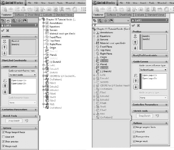
You may correctly ask “What's the difference?” The difference is that when you do something like editing a sketch plane, the current state of the FeatureManager is covered and replaced by the PropertyManager. You may have had the new plane you wanted to use in view. Especially with long FeatureManagers, in both parts and assemblies, when the flyout appears, you have to again scroll to find the plane that was right in view. However you use the detachable PropertyManager, I think you will find it an improvement over the flyout.
On the downside of the detachable PropertyManager, its implementation appears to be incomplete. It does not always automatically expand when needed, and it seems to experience some graphics or display problems, such as target areas for the check and X controls not being directly over the graphics for the control.
Summarizing Part Modeling Best Practice
This section is a summary of best practice suggestions for modeling parts. Best practice lists are important because they lay the groundwork for usage of the software, which is helpful for new users and users who are trying to experiment with the limits of the software.
I believe that it is only after you respect the rules and understand why they are so important, that you know enough to break them. However, best practice lists should not be taken too seriously. They are not inflexible rules, but conservative starting places; they are concepts that you can default to, but that can be broken if you have good reason. Following is a list of suggested best practices:
- Always use unique filenames for your parts. SolidWorks assemblies and drawings may pick up incorrect references if you use parts with identical names.
- Using Custom Properties is a great way to enter text-based information into your parts. Users can view this information from outside the file by using applications such as Windows Explorer, SolidWorks Explorer, and Product Data Management (PDM) applications.
- Learn to sketch using automatic relations.
- Use fully dimensioned sketches when possible. Splines are often impractical to fully dimension.
- Limit your use of the Fixed constraint.
- When possible, make relations to sketches or stable reference geometry, such as the Origin or standard planes, instead of edges or faces. Sketches are far more stable than faces, edges, or model vertices, which change their internal ID at the slightest change and may disappear entirely with fillets, chamfers, split lines, and so on.
- Do not dimension to edges created by fillets or other cosmetic or temporary features.
- Apply names to features, sketches, and dimensions that help to make their function clear.
- When possible, use feature fillets and feature patterns rather than sketch fillets and sketch patterns.
- Combine fillets into as few fillet features as possible; this also enables you to control fillets that need to be controlled separately — such as fillets to be removed for Finite Element Analysis (FEA), drawings, and simplified configurations — or added for rendering. The trade-off is that troubleshooting is more difficult with fillets that use more edges.
- Create a simplified configuration when building very complex parts or working with large assemblies.
- Model with symmetry in mind. Use feature patterns and mirroring when possible.
- Use link values or global variables to control commonly used dimensions.
- Do not be afraid of configurations. Control them with design tables where there are more than a few configs, and document any custom programming or automated features in the spreadsheet for other users.
- Use display states when possible instead of configurations.
- Use multi-body modeling for various techniques within parts; it is not intended as a means to create assemblies within a single part file.
- Cosmetic features — fillets, in particular — should be saved for the bottom of the design tree. It is also a good idea to put them all together into a folder.
- Use the Tools Options Performance Verification on Rebuild setting in combination with the Ctrl+Q command to check models periodically and before calling them “done.” The more complex the model, or the more questionable some of the geometry or techniques might be, the more important it is to check the part.
- Always fix errors in your part as soon as you can. Errors cause rebuild time to increase, and if you wait until more errors exist, troubleshooting may become more difficult.
- Troubleshoot feature and sketch errors from the top of the tree down.
- Do not add unnecessary detail. For example, it is not important to actually model a knurled surface on a round steel part. This additional detail is difficult to model in SolidWorks, it slows down the rebuild speed of your part, and there is no advantage to actually having it modeled (unless you are using the model for rapid prototype or to machine a mold for a plastic part where knurling cannot be added as a secondary process). This is better accomplished by a drawing with a note. The same concept applies to thread, extruded text, very large patterns, and other features that introduce complex details.
- Do not rely heavily on niche features. For example, if you find yourself creating helices by using Flex/Twist or Wrap instead of Sweep, then you may want to rethink your approach. In fact, if you find yourself creating a lot of unnecessary helices, then you may want to rethink this approach as well, unless there is a good reason for doing so.
- File size is not necessarily a measure of inefficiency.
- Be cautious about accepting advice or information from Internet forums. You can get both great and terrible advice from people you don't know, along with everything in-between. Sometimes even groups of people can be dead wrong. Get someone you trust to verify ideas, and as always, test them on copied data to determine if they're effective.
If you are the CAD Administrator for a group of users, you may want to incorporate some best practice tips into standard operating procedures for them. The more users that you manage, the more you need to standardize your system.
Cross-Reference
Best practice development is covered at length in the SolidWorks Administration Bible (Wiley, 2009).
Using the Skeleton Approach
The term Skeleton in Pro/ENGINEER has a different significance than the way it is being used here. SolidWorks does not have any feature or function named “skeleton.” The term just refers to a technique and a set of sketches, planes, axes, and reference points used to lay out the major faces and features of a part.
The SolidWorks Help files, tutorials, and training curricula have encouraged users in some respects to take a “fast and loose” approach to modeling, which is great for initial modeling speed but not so good for design for change. The main consideration seems to be the simplest way to do something, or how it could be done rather than how it should be done. This mentality fit well with the initial several releases of the SolidWorks software, which at that time was marketed as being simple and fast.
The software has progressed immensely since those days. It is now entirely plausible to create complex castings and plastic parts with many hundreds of features, weaving in and out of surface and solid techniques, multi-bodies, and external references. This is a far cry from the typical tutorial or training part, which still tend to have fewer than 15 features, half of which may be fillets. With the simpler parts, you hardly give a thought to parent/child relationships, rebuild times, or the consequences of making changes that cause a feature to fail, because the whole part can be rebuilt from scratch in ten minutes anyway.
SolidWorks users have traditionally been taught to build each feature linearly, on top of the one that came before. This is the genealogical equivalent of each generation having a single child, and then that child having a single child, and so on. The family tree, or FeatureManager, winds up looking like a long staircase, with each generation related only to the generation immediately before it. In the SolidWorks world, this creates long, linear, daisy-chained relationships between consecutive features. The main downside to this is that when a single feature fails, everything below it also fails.
It turns out that this is not a great idea, especially as the parts begin to get more complex. When each feature is dependent upon the one before it, all the features must be solved in a particular order, and if one feature fails, so do all the features that come after it. This also slows down the rebuilding process. Especially as we move into the age of parallel multi-threaded processing, a linear set of commands or features must be executed in order one after the other, and there is really little room for parallel processes.
The sophistication of the documentation provided with SolidWorks has not kept pace with the sophistication of either the software or its users, which I suppose is why you are reading this book rather than the help files provided with the software. The documentation is still based on the simple scenarios, and the advanced user is left to figure things out on his or her own.
As the software gets more sophisticated, the models created with the software can become more sophisticated, and the methods used to build the models must become more sophisticated, as well. It's time to leave the linear modeling approaches behind.
Rather than using a linear daisy-chain modeling scenario, it is better practice to base features on entities that are less likely to fail or change in such a way that dependent downstream features also fail. In earlier chapters, I have suggested that you make sketch relations to other sketches when possible instead of model edges for this very reason.
Taking that scenario one step further, what if a handful of sketch and plane features were used to centralize control of all of the rest of the features? What if every feature, to the extent possible, related back to these “skeleton” features? Features such as fillets, shell, and draft by design require selections from solid geometry, but other features, such as any feature created from sketches, could be made with only reference to those original skeleton sketches and planes. The parent/child relationship would look very different for a model made in this way. Instead of looking like a long staircase, this tree would look more like a tree that gets wide very quickly. There would be fewer “generations,” but each generation would be more populated. The main upshot of this is that if any feature fails, the dependent features that fail should be minimized.
The first thing to notice is that errors in features at the top of the tree do not cascade down the tree as they do in the “stairstep” model. Second, it is always much easier to find how a model is constructed, because all the reference geometry used to build it is set up in the first few features. This scenario also has the potential to make better use of multi-threaded processing because the logic is less linear and more parallel.
On the DVD
Examine the part on the DVD for Chapter 12 called Chapter 12 Sketleton.sldprt. Roll back the FeatureManager and examine it. Notice that sketches do not reference faces or edges of the part, but other sketches and planes.
Using Evaluation Techniques
You can use evaluation techniques to evaluate geometry errors, demonstrate the manufacturability of a given part, or to some degree quantify aesthetic qualities of a given part, or section of a part. I discuss evaluation techniques here because the design cycle involves iterations around the combination of create-evaluate-edit-evaluate functions. I discuss the following techniques in this section:
- Verification on rebuild
- Check
- Zebra Stripes/RealView/Lights and specularity
- Curvature display
- Deviation analysis
- Tangent Edges as Phantom
- Geometry Analysis
- Feature statistics
- Curvature comb
- DFMXpress (Design For Manufacturability)
- SimulationXpress
Many of these techniques apply specifically to plastic parts and complex shapes, but even if you do not become involved in these areas of design or modeling, these tools may help you to find answers on other types of models as well.
A special tab called Evaluate appears in the CommandManager; this tab has much of the functionality that is discussed in this chapter. You can use the commands on this tab to evaluate parts in several ways. Some focus on plastic parts or thin-walled parts or symmetric parts, and so on. Most of these tools are from the Tools toolbar but are found on the Evaluate tab in the Command Manager.
Using Verification on rebuild
Verification on rebuild is an option that you can access by choosing Tools ![]() Options
Options ![]() Performance
Performance ![]() Verification on rebuild. Under normal circumstances (with this setting turned off), SolidWorks checks each face to ensure that it does not overlap or intersect improperly with every adjacent face. Each face can have several neighbors. This option is shown in Figure 12.7.
Verification on rebuild. Under normal circumstances (with this setting turned off), SolidWorks checks each face to ensure that it does not overlap or intersect improperly with every adjacent face. Each face can have several neighbors. This option is shown in Figure 12.7.
FIGURE 12.7 The Verification on rebuild option

With the setting selected, SolidWorks checks each face with every other face in the model. This is a better check than with the setting off but greatly increases the workload. The switch is deselected by default to prevent rebuild times from getting out of control. For most parts, the default setting is sufficient; however, when parts become complex, you may need to select the more advanced setting.
If you are having geometry or rebuild error problems with a part and cannot understand why, then try turning Verification on rebuild on and pressing Ctrl+Q. Ctrl+Q applies the Forced Rebuild command and rebuilds the entire design tree. Ctrl+B, or the Rebuild command, only rebuilds what SolidWorks determines needs to be rebuilt.
If you see additional errors in the design tree that were not there before, then the combination of Verification on rebuild and Forced Rebuild has identified problem areas of the model and the features that caused the errors failed. If not, then your problem may be elsewhere. You still need to fix any errors found this way.
Performance
For speed reasons, it is normal practice to turn Verification on rebuild off, and to use it selectively to check models with potential errors. The type of speed degradation that you can see is dependent on the number of faces and bodies in the model. Some of the performance degradation as relates to patterns is documented in Chapter 9.
Using the Check tool
![]() Check is a tool that checks geometry for invalid faces and other similar geometry errors. It is also often used to find open edges of surface bodies, short edges, and the minimum radius on a face or entity. I usually apply the Check tool before selecting the Verification on rebuild option. The Check tool points to specific face or edge geometry (not features or sketches) that is the cause of the problem. When the Check tool finds general faults, the locations it points to may or may not have something obvious to do with a possible fix.
Check is a tool that checks geometry for invalid faces and other similar geometry errors. It is also often used to find open edges of surface bodies, short edges, and the minimum radius on a face or entity. I usually apply the Check tool before selecting the Verification on rebuild option. The Check tool points to specific face or edge geometry (not features or sketches) that is the cause of the problem. When the Check tool finds general faults, the locations it points to may or may not have something obvious to do with a possible fix.
Much of the time, the best tool for tracking down geometry errors is the combination of experience and intuition. It is not very scientific, but you come to recognize where potential problems are likely to arise, such those that occur when you attempt to intersect complex faces at complex edges, sharp or pointy geometry, and geometry or faces that vary significantly from rectangular with 90-degree corners. Figure 12.8 shows the Check Entity dialog box.
FIGURE 12.8 The Check Entity dialog box

Evaluating geometry with reflective techniques
Evaluating complex shapes can be difficult. A subjective evaluation requires an eye for the type of work you are doing. An objective evaluation requires some sort of measurable criteria for determining a pass or fail, or a way for you to assign a score somewhere in the middle.
One way to subjectively evaluate complex surfaces, and in particular the transitions between surfaces around common edges, is to use reflective techniques. If you look at an automobile's fender, you can tell whether it has been dented or if a dent has been badly repaired by seeing how the light reflects off of the surface. The same principle applies when evaluating solid or surface models. Bad transitions appear as a crease or an unwanted bulge or indentation. The goal is to turn off the edge display and not be able to identify where the edge is between surfaces for the transition to be as smooth as if the whole area were made from a single surface.
With all of the RealView functionality in SolidWorks that emphasizes reflective finishes and backgrounds that emphasize the reflections, sometimes the RealView Appearance and Scenes are all you need to employ reflective evaluation techniques. Chapter 5 covers all of the display information you need to make the most of RealView, Appearances, and Scenes.
Using Zebra Stripes
![]() Zebra Stripes can be activated one of two ways, by choosing View
Zebra Stripes can be activated one of two ways, by choosing View ![]() Display
Display ![]() Zebra Stripes from the menus or by clicking a toolbar button on the View toolbar. Zebra Stripes place the part in a room that is either spherical or cubic, where the walls are painted with alternating black-and-white stripes (although you can change the colors and the spacing of the stripes). The part is made to be perfectly reflective, and the way that the stripes transition over edges tells you something about the qualities of the faces on either side of the edge. Four conditions are of particular interest:
Zebra Stripes from the menus or by clicking a toolbar button on the View toolbar. Zebra Stripes place the part in a room that is either spherical or cubic, where the walls are painted with alternating black-and-white stripes (although you can change the colors and the spacing of the stripes). The part is made to be perfectly reflective, and the way that the stripes transition over edges tells you something about the qualities of the faces on either side of the edge. Four conditions are of particular interest:
- c0 = faces contact at edge
- c1 = faces are tangent at edge
- c2 = curvature of each face is equal at the edge and the transition is smooth
- c3 = rate of change of curvature of each face is equal at the edge
The Zebra Stripes tool can only help you identify c0, c1, and c2, and only subjectively. This feature is of most value between complex faces. Figure 12.9 illustrates how the Zebra Stripes tool shows the differences between these three conditions.
FIGURE 12.9 Contact, tangency, and curvature continuity
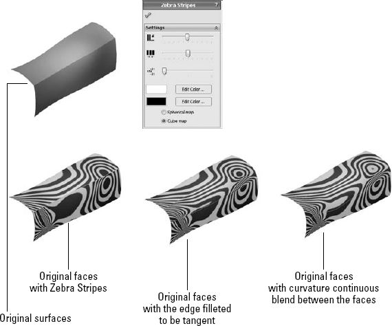
Notice how on the Contact-only model, the Zebra Stripe lines do not line up across the edge. On the Tangent example, the stripes line up across the edges, but the stripes themselves are not smooth. On the Curvature Continuous example, the stripes are smooth across the edges. The part shown in Figure 12.9 is a surface model and can be found on the DVD with the filename Chapter 12 Zebra Stripes.sldprt.
You should rotate the model a lot when you are using the Zebra Stripes tool. Changing the density of the lines can also help, as can increasing the image quality (Tools ![]() Options
Options ![]() Document Properties
Document Properties ![]() Image Quality). Turning off the edge display may also help.
Image Quality). Turning off the edge display may also help.
Using RealView
![]() RealView Graphics display is only available to users with certain types of video cards. To see whether your card supports RealView, consult the system requirements on the SolidWorks Web site.
RealView Graphics display is only available to users with certain types of video cards. To see whether your card supports RealView, consult the system requirements on the SolidWorks Web site.
RealView causes reflections that can be used in a way similar to the reflections in Zebra Stripes. Rotate the part slowly and watch how the reflections flow across edges. Instead of black and white stripes, it uses the reflective background that is applied as part of the RealView Scene.
Cross-Reference
RealView techniques and usage are covered in more depth in Chapter 5.
Using Curvature display
![]() Model curvature can be plotted onto the model face using colors, as shown in Figure 12.10. The accuracy of this display leaves a bit to be desired, but it does help you identify areas of very tight curvature on your part. Areas of tight curvature can cause features such as fillets and shells to fail.
Model curvature can be plotted onto the model face using colors, as shown in Figure 12.10. The accuracy of this display leaves a bit to be desired, but it does help you identify areas of very tight curvature on your part. Areas of tight curvature can cause features such as fillets and shells to fail.
FIGURE 12.10 Curvature display
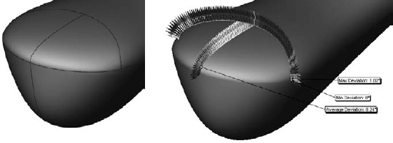
Using Deviation Analysis
![]() Deviation Analysis measures how far from tangent the surfaces on either side of a selected edge actually are. For example, the edges shown in Figure 12.11 are found to be fair, but not very good. I prefer deviations of less than 0.5 degrees. Often with some of the advanced surface types such as Fill and Boundary, SolidWorks can achieve edges with less than 0.05-degree maximum deviation.
Deviation Analysis measures how far from tangent the surfaces on either side of a selected edge actually are. For example, the edges shown in Figure 12.11 are found to be fair, but not very good. I prefer deviations of less than 0.5 degrees. Often with some of the advanced surface types such as Fill and Boundary, SolidWorks can achieve edges with less than 0.05-degree maximum deviation.
While Deviation Analysis helps to quantitatively measure how close to tangent the faces on either side of the selected edge are, it does not tell you anything about curvature, so you must still run Zebra Stripes to get the complete picture of the flow between faces. Both tests have to return good results to have an acceptable face transition.
FIGURE 12.11 An example of Deviation Analysis
Using the Tangent Edges as Phantom setting
Using the Tangent Edges as Phantom setting is an easy way to evaluate a large number of edges visually. This function does not do what the Zebra Stripes tool does, but it gives you a good indication of the tangency across a large number of edges very quickly. Again, it only represents tangency, and tells you nothing about curvature continuity. Nor does it give you as detailed information as the Deviation Analysis; it only tells you whether SolidWorks considers the faces to be tangent across the edge. Several releases ago, SolidWorks widened the tolerance of what it considers to be tangent, which is both good and bad news. It's good because features that require tangency will work more frequently, and it's bad because if fractional tangency degrees matter to you, “close” is not close enough. If you use Tangent Edges as Phantom as an analysis technique, you should also follow it up with Deviation Analysis to find out how close you actually are.
I have not seen this function deliver false positives (edges displayed as tangent when in fact they were not), but I have seen many false negatives (edges that display as non-tangent when in fact they were). Figure 12.12 shows a situation where the edges are displayed with solid edges, but Deviation Analysis shows them to have a zero-degree maximum deviation.
FIGURE 12.12 Using the Tangent Edges as Phantom setting

The measure of tangency has some tolerance. Users cannot control the tolerance, nor does the documentation say what it is. If SolidWorks says two faces are not tangent at an edge, you can believe that, but if SolidWorks says that the faces are tangent, you still have to ask how tangent. That is the question that Deviation Analysis can answer.
Using Geometry Analysis
![]() Another tool that is fairly new is the Geometry Analysis tool. You can find it in the Tools menu or the new Evaluate tab in the Command Manager. It is an extremely useful tool for troubleshooting problematic geometry. The PropertyManager, shown in Figure 12.13, allows you to look for several specific items:
Another tool that is fairly new is the Geometry Analysis tool. You can find it in the Tools menu or the new Evaluate tab in the Command Manager. It is an extremely useful tool for troubleshooting problematic geometry. The PropertyManager, shown in Figure 12.13, allows you to look for several specific items:
- Short edges
- Small faces
- Sliver faces
- Knife edges/vertices
- Discontinuous faces or edges
FIGURE 12.13 Using Geometry Analysis to find typical problem spots

These specific types of geometry typically cause problems with other features, such as shells or fillets. If you are having difficulty with a feature failing for a reason that you can't explain, use the Geometry Analysis tool to point out potential problem spots. This is not a tool that will do your job for you, but it is a tool that gives you useful information to help you do your job better with less guesswork.
Geometry analysis is only available with SolidWorks Professional and higher.
Using Feature Statistics
![]() The Feature Statistics tool has been used previously in this book to measure rebuild times for individual features in parts. You can find it either in the Tools menu or the Evaluate tab of the Command Manager.
The Feature Statistics tool has been used previously in this book to measure rebuild times for individual features in parts. You can find it either in the Tools menu or the Evaluate tab of the Command Manager.
Feature Statistics lists the rebuild times of each individual feature in a part. This is useful for researching features, benchmarking hardware or versions of SolidWorks, and developing best practice recommendations for different tools and techniques. Figure 12.14 shows the Feature Statistics interface.
FIGURE 12.14 Feature Statistics helps you analyze rebuild times for features.
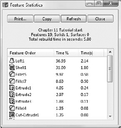
Overall, I do not recommend relying too heavily on the data the Feature Statistics tool provides; this is not because it is inaccurate but because rebuild time is not always the best way to evaluate a model. You can certainly use the information, but you also need to keep it in perspective. A feature that takes a long time to rebuild but gives the correct result is always better than any feature that does not give the correct result, regardless of rebuild time.
Using the Curvature Comb
![]() The Curvature Comb is a graphical tool you can apply to a spline, circle, arc, ellipse, or parabola to indicate the curvature along the length of the curve. You cannot apply a Curvature Comb to a straight line because a straight line has no curvature. The height of the comb indicates the curvature. Curvature is defined as the inverse of radius (c=1/r), so that as the radius gets smaller, the curvature gets bigger.
The Curvature Comb is a graphical tool you can apply to a spline, circle, arc, ellipse, or parabola to indicate the curvature along the length of the curve. You cannot apply a Curvature Comb to a straight line because a straight line has no curvature. The height of the comb indicates the curvature. Curvature is defined as the inverse of radius (c=1/r), so that as the radius gets smaller, the curvature gets bigger.
Figure 12.15 shows a curvature comb applied to a spline. Notice that the spline continuously changes curvature. An arc has constant curvature.
FIGURE 12.15 A Curvature Comb shows the constantly changing curvature of the spline.
When the comb crosses the spline, it means that the direction of curvature has changed. When the comb intersects the spline, it means that the spline at that point has no curvature.
Cross-Reference
The Curvature Comb is discussed in depth in the SolidWorks Surfacing and Complex Shape Modeling Bible (Wiley, 2008).
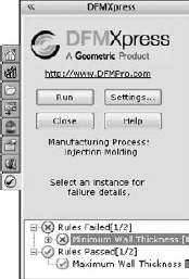
Using DFMXpress to catch manufacturability problems
DFMXpress is a free add-in to the software that may entice you to buy a higher functionality product. DFMXpress may provide some first-level manufacturability guidance for novice designers and engineers or those unfamiliar with one of the four processes that DFMXpress supports.
DFMXpress checks various rules for parts to be manufactured using the following processes:
- Mill/Drill
- Turn with Mill/Drill
- Sheet Metal
- Injection Molding
For each process, the user must establish some rule parameters. For example, for injection molding, the parameters are minimum and maximum wall thickness. It makes no mention of draft or undercuts. For Sheet Metal, you must set various thickness ratios for minimum hole diameter, bend radius, standard hole sizes, and so on. The evaluation tool requires some minimum setup, and some input from an experienced person in your operation. It is certainly not complete, or a replacement for an expert, but it offers a great first look at the geometry to check that the most obvious errors are caught before it leaves your desk.
You can activate DFMXpress from the Tools menu, and it runs in the Task Pane. Figure 12.16 shows DFMXpress in action on an injection-molded part. The results point to specific faces that fail specific rules, so when it fails, you know exactly where and why.
FIGURE 12.16 Reading results in DFMXpress
Analyzing with SimulationXpress
SimulationXpress (formerly COSMOSXpress) is a limited version of SolidWorks Simulation (formerly COSMOS Works) that is bundled with SolidWorks to acquaint users with FEA. The full version of SolidWorks Simulation does a wide range of analysis, from vibrations to large deformations. SimulationXpress is a very quick and easy wizard for simple stress analysis on stand-alone parts with simple constraints. It does simple linear stress analysis on a single part with a single material using only fixed constraints and a load. You can also use SimulationXpress to do a simple stress/weight optimization based on dimensions that you select to be altered.
You can start SimulationXpress through the Tools menu, or from the Evaluate tab of the CommandManager. The interface guides you through a very simple wizard. If you have any familiarity with FEA applications, you will find SimulationXpress easy to understand and use, but possibly lacking in flexibility or capability.
SimulationXpress uses a combination of the Task Pane on the right of the graphics window and the PropertyManager on the left side of the graphics window. In this book, I am using the detached PropertyManager, so I can position it for more compact screen shots.
SimulationXpress is intended as a quick and dirty analysis run to see whether you are even close to having a part that will stand up to the loads you apply to it. As with any type of analysis, the results are only of value if the setup was correct and if you are able to interpret the results.
In this chapter I do not aim to teach analysis theory or best practice; this is simply a quick overview of how to use the tool. FEA is a field of study unto itself, and you should learn it from a dedicated resource. Analysis is a field that depends on approximations and simplifying assumptions. Knowing how and when to make the correct approximations and assumptions along with being able to interpret approximated results are some of the keys to success not provided by this book.
As you step through the process, the notes in the Task Pane seem to continually prompt you that various conditions will require the next level higher (not free) in order to correctly solve the model. SimulationXpress is clearly a sales and marketing tool, but if your needs are simple, and you understand the process, you may be able to get useful information from it.
Welcome to SolidWorks SimulationXpress
When you start SimulationXpress, an image welcomes you to the tool and lets you know what to expect from the process. It also issues a disclaimer that seems to downplay the value of this tool. There is also a link here for some valuable Web-based training if you are new to analysis or simulation. Figure 12.17 shows the new Welcome screen.
FIGURE 12.17 Welcoming you to the SimulationXpress software
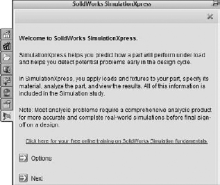
If you are a veteran SimulationXpress user, most of what you see here may be new, including the order of the steps and some of the terminology.
Applying Fixtures
Every analysis must have at least one face that is held stationary in order for the analysis to work. These are usually faces on the bottom of the part.
In the past, Fixtures were referred to as Restraints. You must apply Fixtures to the part to be analyzed as the first step in the process. A PropertyManager appears to collect the faces you select. Fixtures are fixed, meaning they are the faces in the analysis that remain perfectly stationary. These are usually some sort of mounting location or a welded area.
On this part, I have used the Split Line feature to split out areas of the bottom face around the bolt holes to represent sections of the part that will not move regardless of how much force is applied to the part.
The dark blue underlined text in the Task Pane offers links to simple animations showing some possibilities for assigning Fixtures. Clicking the Add a fixture link in the Task Pane brings up the Fixture PropertyManager, shown in Figure 12.18.
FIGURE 12.18 Assigning fixed faces using the Fixture PropertyManager

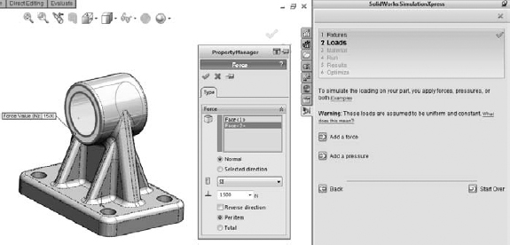
Applying Loads
You can apply forces or pressures to model faces. Forces are normal to selected faces by default, but you can select an axis, edge, or sketch element to specify a selected direction for the force. Again links in the Task Pane enable you to see small video hints or tool tips. Figure 12.19 shows the Loads interfaces.
FIGURE 12.19 Applying loads to the model in SimulationXpress
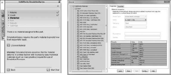
Selecting a material
The third step in setting up SolidWorks SimulationXpress is to assign a material. Once you have made your selection, click Apply. Figure 12.20 shows some of the materials selection. Materials can be created or customized in the same way that you would create or customize standard SolidWorks materials.
FIGURE 12.20 Assigning a material in SimulationXpress
Tip
My experience with the early versions of SimulationXpress in SolidWorks 2010 sp0.0 has been that much of the tool did not work properly the first time. It took several tries to get a material to apply, the loads appeared to be applied incorrectly, and the initial screen did not appear when I first started the software.
Running the analysis
Analyzing simple parts on modern computers usually takes a matter of seconds. Because SimulationXpress is limited to single parts, most analyses you run will not take very long. You need to make sure that you have green check marks to the right of Fixtures, Loads, and Material before you can run the analysis. Figure 12.21 shows the analysis of this part in the process of running.
Visualizing the results
SimulationXpress makes three different types of results available to you:
- vonMises stress plot
- Displacement plot
- Factor of Safety (FOS) plot
FIGURE 12.21 Running the analysis

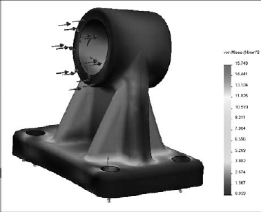
Each of these can be animated. The deformation shown by the model is exaggerated by a deformation scale factor, which is shown as part of the legend on the screen. It is typically around 1000x. Deformation is exaggerated to make it easier to visualize how the structure flexes under load.
Figure 12.22 shows a deformed vonMises stress plot.
FIGURE 12.22 Visualizing the results of the stress analysis
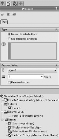
All the values that you enter and faces that you select are stored in the SimulationXpress Study panel, which shows up by default on the bottom in a split PropertyManager, as shown in Figure 12.23. This is saved with the part and is displayed any time you have the SolidWorks SimulationXpress panel open in the Task Pane.
FIGURE 12.23 Accessing the results and inputs for the study in the lower panel of the PropertyManager
Optimizing the design
The final step in the Simulation process, if you choose to use it, is the Optimization. Optimization enables you to vary a dimension of the part and run multiple studies to determine what value for that dimension produces the best result.
Optimization displays another panel at the bottom of the graphics window that enables you to establish a range for the dimension that will be varied during the optimization. This panel is shown in Figure 12.24.
When you run the optimization, SolidWorks will change the model dimension within the range that you specified and run an analysis for each dimension value. For this to be most successful, you must have a robust model where all the features can adapt to the range of dimensions for the feature being changed.
FIGURE 12.24 Entering a range of sizes for the optimized feature

Troubleshooting Errors
You will encounter many types of errors in SolidWorks. Improper installation or even bad computer hygiene can cause errors that might look like bugs in the software. Software bugs can cause errors that look like training issues. Operator errors can cause problems that are very difficult to sort out. In this book, I do not have the space to go into all of the possible errors and how to work around or fix them, but I will focus on feature-related errors that happen in the course of working on models. If you are interested in debugging errors caused by installation, maintenance, or administrative issues, refer to the SolidWorks Administration Bible (Wiley, 2009).
When you get an error in SolidWorks, figuring out what caused the error and how to fix it is the goal of troubleshooting. Error messages appear in several places, including in message boxes in the graphics window, in the Task Bar, in tool tip bubbles next to the PropertyManager, and in small symbols within the FeatureManager window.
Interpreting rebuild errors
Chapter 3 discusses sketch colors and troubleshooting errors in sketches. You can apply much of what you learned from troubleshooting sketches to troubleshooting features in parts. The FeatureManager displays yellow triangles with black exclamation marks that point out some sort of warning. A warning means that there is a problem, but that the feature has not failed. The red circle with an X in it is a failure symbol, and it means that the feature does not create any geometry.
Figure 12.25 shows a portion of a feature tree of a part from which a feature in the middle of the tree was deleted. Unless you are very careful about how you set up your part, a deletion of this kind will result in a lot of errors.
Notice the tool tip balloon in Figure 12.25. Many users get in the habit of clicking out of any sort of warning or error message. You shouldn't be afraid of errors. Once you know how to deal with them, you will think of errors as a tool to help you investigate your model. The first thing you should do with an error message is read it. Eventually, you will be able to recognize error messages and their meanings very quickly.
FIGURE 12.25 Deleting a feature in the middle of a tree can cause a lot of errors.

This error message says, “The intended cut does not intersect the model. Please check the sketch and direction.” This means that you have a cut that is cutting air. This is because the feature it was cutting was deleted. You may know the cause of errors or you may not. If you had inherited this part from someone else who did not explain the state of the model to you, you might have to figure it out yourself. Most of the time, it is not difficult to figure out what is going on.
When you inherit a model with errors, the first thing you should do is look for the error that is highest in the tree. When you make a change that causes errors, these errors are almost always lower in the tree than the change. Special situations can arise where a change causes an error up the tree, but they are rare.
Here are some common error messages and what they are really trying to tell you:
- Some Items are no longer in the model. You can reselect the items using the Edit Definition in the FeatureManager design tree. The first thing to know here is that Edit Definition has been gone for several releases now. Edit Feature is the name of the command you will be looking for. You can get this message when an edge or a face for a selected feature no longer exists. A number of things can cause it, but the culprit is usually changes to the model upstream. As a result, if you roll back the model, and make changes (especially if you delete something, but adding features can also cause errors of this sort), you can expect some problems when you unroll the model.
- Operation failed due to geometric condition. This is one that frustrates a lot of users, because “geometric condition” is vague and could mean just about anything related to geometry. It can sometimes mean that a selection set is incomplete — the feature requires another face or another edge to be selected in order to work, or a fillet cannot work because an edge flips convexity, or a sketch line does not cut all the way across a solid body. There are too many possibilities to list, but it is a clue that you need to check either the selections for the feature or the body on which the feature is operating. In more complex cases, it might mean that the part has some geometrical errors that you need to figure out by using the Check tool or Verification on Rebuild.
- Warning: This sketch contains dimensions or relations to model geometry which no longer exists... This is one of the better messages that SolidWorks provides. It is fairly self-explanatory and goes on to give you a couple of useful suggestions as to how you might fix the problem.
- Some filleted items are no longer in the model. Edit the feature to reselect the items. When all of the edges selected in a fillet feature are suddenly not there, the entire fillet feature fails because there is nothing to do. This warning displays the red circle with the X in it. Some edges may remain selected, and the fillet feature can still work. In these cases, you will get the next message, which is just a warning rather than an error.
- Warning: Edge for fillet/chamfer does not exist. In this case, you see the yellow triangle warning, and the fillet still creates some fillets, but one of the selected edges is missing, and the feature can't create all of the fillets it created originally. The fastest way to fix this warning is to right-click it, select Edit Feature, and then immediately click the green check icon. SolidWorks displays a message to make sure that you want to just remove the references to the missing edge, but will continue to create fillets on the selected edges. Another option is to find the missing edge in the selection box and reselect an edge to take its place.
Many more types of errors exist, and rather than going through an exhaustive list, which would require another book of its own, I would like to impart to you some guidelines to help you find a useful answer. Hopefully you only have to figure out an error once, and you will remember it the next time you see it. Here are some general guidelines for troubleshooting errors with causes that aren't obvious:
- CAD in general does not like line-on-line geometry. In SolidWorks, you don't get extra points for being close. Most features require you to be exact or so close that it looks exact. It is often a good idea to “overbuild” geometry so that it is bigger than it needs to be if it is going to merge with other geometry.
- Zero thickness errors. Zero thickness errors can be some of the most difficult for users that are new to 3D to diagnose. Much in the same way that CAD doesn't like line-on-line geometry, it doesn't like edges that create a section of a single body where there is air on two sides of an edge. If you were to extrude two rectangles that touch at a point, SolidWorks would create two separate bodies from that point, because it physically would fall apart if it were a single body. If the two touching rectangles were also trying to merge with an existing solid body, you would get an error.
- Planar means planar. If you click on a face, and it just won't let you open a sketch, maybe the face is not planar. Errors of this sort can happen in surfacing applications and imported geometry quite often. I use the Sketch icon as a quick test for whether or not a face is planar. SolidWorks doesn't really give you another way to measure this. Non-planar faces can also cause a lot of trouble with assembly mates.
- Even if it's planar, is it square to the coordinate system? If you work with plastic parts or castings, or anything else that requires draft, you can and probably do have faces that are not perpendicular or parallel to the standard reference planes. This can cause problems with projections (a circle projected at an angle becomes an ellipse, and an ellipse projected at an angle becomes a spline) and extrusion directions.
- If it doesn't like one method, try another that produces similar results. One common example of this is when a constant radius fillet will not work, and you think it should work. In this case, try to use a variable radius fillet with all the same radius values.
For most errors, a rational reason exists. Belief in supernatural forces is not likely to be useful when troubleshooting errors in SolidWorks. If you are using very common features such as extrudes and cuts and you run into errors, it is very unlikely that you have found a bug (although bugs in sketches are quite common). Generally speaking, the more traffic a feature sees, the less likely you are to find bugs with it. Sometimes just determining whether the problem is with the software or with something you are doing is the toughest thing to troubleshoot. In general, users are far too eager to assign blame to the software.
Using SolidWorks RX and Performance Benchmark
SolidWorks provides a couple of automated troubleshooting tools: SolidWorks RX and Performance Benchmark. SolidWorks RX troubleshoots your system, or at least records facts about your system so someone trained in how to view the results can diagnose the problem.
Using SolidWorks RX
SolidWorks RX is a diagnostic tool that SolidWorks provides to help support techs solve your problem or to help you solve it yourself. You can access SolidWorks RX through the Windows Start menu ![]() All Programs
All Programs ![]() SolidWorks 2011
SolidWorks 2011 ![]() SolidWorks 2011 Tools
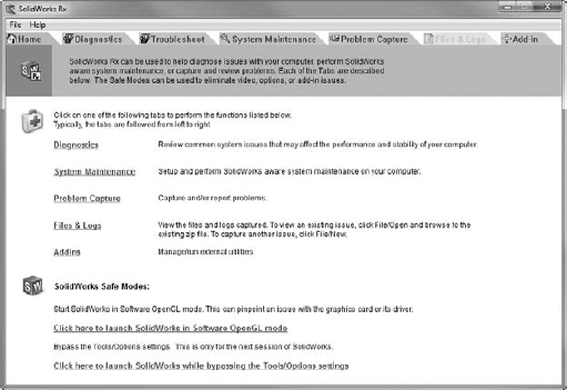
SolidWorks 2011 Tools ![]() SolidWorks RX. Figure 12.26 shows the Home page of the interface.
SolidWorks RX. Figure 12.26 shows the Home page of the interface.
FIGURE 12.26 Using SolidWorks RX
Using the Diagnostics tab
The first tab in the SolidWorks RX interface is a self-help diagnostics list, shown in Figure 12.27. This points out that my computer is a less common brand (Xi), that it is compatible with my video card, and that the driver is out of date (it gives me the option to download the correct driver); it also lists other information related to system maintenance.
FIGURE 12.27 Using the SolidWorks RX Diagnostics tab

The items in the Diagnostics tab are things that a support tech might ask you about if you were to call with a crash problem or some other problem that might be related to general system issues. Running SolidWorks RX before calling tech support could save you time and make you more self-reliant.
Using the Troubleshoot tab
The Troubleshoot tab contains mostly links to the SolidWorks Knowledge Base, for which you will need a subscription login. These links are useful, and it is a good idea to check them out before calling tech support.
Using the System Maintenance tab
The System Maintenance tab contains paths to critical SolidWorks and system folders. If you click the Start Maintenance button in the upper-right corner, SolidWorks RX clears all the files from the listed paths. If you use the Browse buttons, you can clear paths individually. These are generally temporary and backup folders, so make sure you do not need any of the files before clearing them. Figure 12.28 shows the System Maintenance tab.
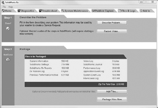
Using the Problem Capture tab
Often when you call your reseller tech support, and you are having some sort of difficulty that is not readily explained, the technician will ask you to submit a SolidWorks RX log file. This log file includes the information from the other tabs, along with an optional description of the problem, SolidWorks files that were in use when the problem occurred, and a video of the problem actually happening. Figure 12.29 shows the Problem Capture tab.
FIGURE 12.28 Clearing temp files with the System Maintenance tab
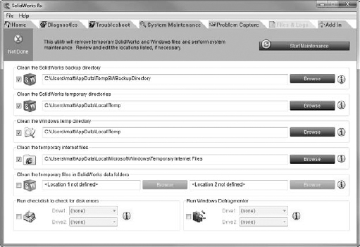
FIGURE 12.29 Collecting information in the Problem Capture tab
Using the Files & Logs tab
The Files & Logs tab shows a summary of the issue and a list of all of the files included in the RX package. You can click on the files that have been added to view their contents before sending the package. The Files & Logs tab is shown in Figure 12.30.
FIGURE 12.30 Listing the files to be sent in the RX package

Using Performance Benchmark
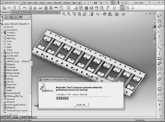
SolidWorks RX has an Add-in tab that allows add-ins to be developed to extend the RX functionality. New for SolidWorks 2011 is the Performance Benchmark add-in. This benchmark runs your installation of SolidWorks through some automated display and rebuild exercises and measures the time for various operations such as zoom, rotate, rebuild, for a part and an assembly. Figure 12.31 shows the interface for the Performance Benchmark test.
This benchmark is similar to an older benchmark application called SPECapc, which was available several years ago and could be used across several different CAD systems. SPECapc still exists (and is available from the Web site www.spec.org), but the SolidWorks benchmark was last updated in 2007. The point of benchmarks like this is to measure hardware capabilities.
Other less formal benchmarks exist, such as Mike Wilson's Ship-in-a-Bottle (www.mikejwilson.com), which is just a surface model with a rebuild macro, where you use Feature Statistics to measure the results. Anna Wood (www.solidmuse.com) also has an informal benchmark with a model of Scooby Doo and a punch plate. None of the informal benchmark models are particularly good at measuring all aspects of the software. There are no assemblies among them, and a couple of them are heavy in surfacing, which makes better use of multi-threading than solid models.
The models for the SolidWorks RX Performance Benchmark are a small, stamped part and an injection-mold die set. Figure 12.32 shows the benchmark in action.
FIGURE 12.31 Running Performance Benchmark

FIGURE 12.32 Putting the computer through its paces with Performance Benchmark
The results of the benchmark test are measured in two ways. One way is in the average number of seconds each test took (where a lower score is better), and the other way is to simply reuse the Windows Experience Index (where a higher score is better), which you can find in the Windows Control panel.
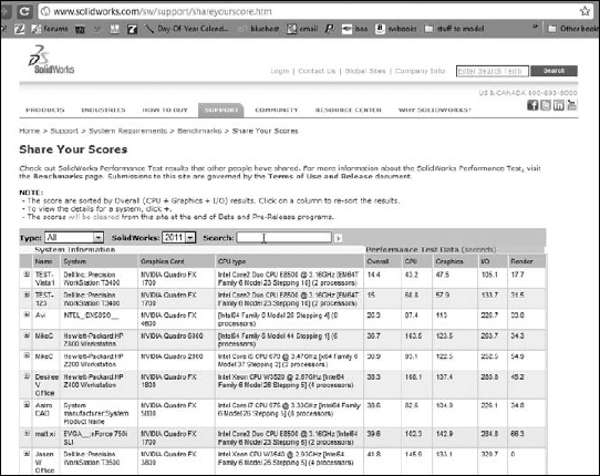
Finally, you can submit your results to the SolidWorks Web site, where they are posted immediately for comparison. This is used to help people make decisions about what hardware to buy. Figure 12.33 shows the local results, and Figure 12.34 shows accumulated results from many users.
FIGURE 12.33 Evaluating your hardware with a SolidWorks RX Performance Benchmark test

You can check out the compared scores at www.solidworks.com/sw/support/shareyourscore.htm. Look through the list to see which kind of hardware receives a consistently high score and which is not represented in the top results. It's nice that these test results are now more formalized, as previously the closest thing to a database of benchmark scores was a spreadsheet on Anna Wood's Web site.
You can find more information on benchmarking and SolidWorks at www.solidworks.com/sw/support/benchmarks.htm.
FIGURE 12.34 Comparing your score against other submitted scores
Tutorial: Making Use of Editing and Evaluation Techniques
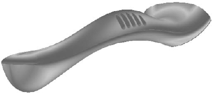
Using this tutorial, you make some major edits to an existing part. You use some simple loft and spline commands and work with the rollback states and feature order, as well as some evaluation techniques. Please follow these steps:
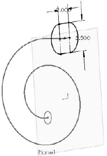
- Open the existing part with the filename Chapter 12 Tutorial Start.sldprt. Roll the part back and step through it feature by feature to see how it was made. Edit the loft feature to see which sketches were used to create it. This can help you to understand how the part was built. Exit the loft command and move the rollback bar back to the bottom of the tree.
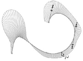
- Open the Deviation Analysis tool (Tools Deviation Analysis). Select the edges, as shown in Figure 12.35.
FIGURE 12.35 Deviation analysis of an existing part
The maximum deviation is about ten degrees, which is far too much. This part needs to be smoothed out, which you can do using splines in place of lines and arcs.
- The first step is to make the outlet all one piece with the spiral. You can do this with a Fit Spline. You need to create the Fit Spline before the loft profiles and after the spiral.
Expand the loft, and roll back between the loft feature and the first sketch. Click OK in response to the prompt, and then roll back to just after the spiral, as shown in Figure 12.36.
FIGURE 12.36 Rolling back to just after the spiral
- Right-click the spiral in the FeatureManager and show it. Open a new sketch on the Top plane.
- Try to draw a horizontal line from the outer end of the spiral. You will notice that you cannot reference the end of the spiral.
Curves that are absorbed into other features are notoriously difficult to work with. Generally, you need to select them from the FeatureManager to do anything at all with them. Also, if you need to reference an end of an absorbed curve, you are better off using Convert Entities to make it into a sketch entity.
- Notice that you cannot select the spiral from the graphics window. Even when selected from the FeatureManager, it appears not to be selected in the graphics window. Ensure that it is selected in the FeatureManager, and then click the Convert Entities button on the sketch toolbar.
- Draw a horizontal line from the outer end of the spiral and dimension it to be 3 inches long, as shown in Figure 12.37.
FIGURE 12.37 Preparing for the Fit Spline

- Select both the converted spiral and the line, and click Tools Spline Tools Fit Spline. Set the Tolerance to .1 and make sure that only the Constrained option is selected. Click OK to accept the Fit Spline. Test to make sure that a single spline is created by moving your cursor over the sketch to see whether the whole length is highlighted.
Note
The Fit Spline feature fits a spline to a set of sketch entities within the specified tolerance. It can be a useful tool for smoothing out sketch geometry.
Caution
Do not exit the Fit Spline by pressing the Enter key as you do with other commands, because it simply exits you out of the command without creating a spline.
- Right-click on spline and select the Curvature Comb. Notice how the comb is affected by the transition from the spiral to the straight line.
- Exit the sketch, and create a new plane. Choose Insert Reference Geometry Plane from the menus. Select the Right plane from the Flyout FeatureManager as the first reference and the outer end of the Fit Spline that you have just created as the second reference. Click OK to accept the new plane. This is illustrated in Figure 12.38.
FIGURE 12.38 Creating a new plane

- Drag the Rollback bar down between Sketch3 and Loft1. If it goes beyond Loft1, then you need to navigate back to this position again.
- Right-click Sketch3 and select Edit Sketch Plane. Select the newly created Plane1 from the Flyout FeatureManager, and click OK to accept the change.
- Notice that the loft profile has moved to a place where it does not belong. This is because the sketch has a Pierce constraint to the spiral, and there are multiple places where the spiral pierces the sketch plane.
Edit Sketch3 and delete the Pierce constraint on the sketch point in the middle of the construction line. Create a Coincident relation between the sketch point and the outer end of the Fit Spline, as shown in Figure 12.39. Do not exit the sketch.
- One of the goals of these edits is to smooth out the part. Remember that the Deviation Analysis told you that the edges created between the lines and arcs in Sketch3 were not very tangent. For this reason, it would be a good idea to replace the lines and arcs in Sketch3 with another Fit Spline.
Right-click one of the solid sketch entities in Sketch3, and click Select Chain.
FIGURE 12.39 Sketch3 in its new location
- Create another Fit Spline using the same technique as in Step 8. Exit the sketch.
- Drag the Rollback bar down one feature so that it is below the Loft. Notice that the Loft feature has failed. If you hold the cursor over the feature icon, the tooltip confirms this by displaying the message, “The Loft Feature Failed to Complete.”
- Edit the Loft feature. Expand the Centerline Parameters panel if it is not already expanded, and delete the Spiral from the selection box. In its place, select the Spiral Fit Spline.
- If the loft does not preview, check to ensure that the Show Preview option is selected in the Options panel, at the bottom.
- If it still does not preview, right-click in the graphics window and select Show All Connectors. Position the blue dots on the connector so that it looks like Figure 12.40.
- Click OK to accept the loft. The loft should be much smoother now than it was before. In addition, the spiral feature should no longer be under the loft; it should now be the first item in the design tree.
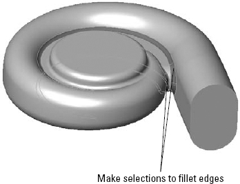
- Drag the Rollback bar down to just before the Shell feature. Notice that Fillet5 has failed. Move the mouse over Fillet5. The tool tip tells you that it is missing some references. Edit Fillet5 and select edges in order to create fillets, as shown in Figure 12.41.
FIGURE 12.40 Positioning the connectors
FIGURE 12.41 Repairing Fillet5
- Right-click in the design tree and select Roll To End. This causes the FeatureManager to become unrolled all the way to the end.
- The outlet of the involute is now longer than it should be. This is because the original extrude was never deleted from the end. Right-click the Extrude1 feature and select Parent/Child. The feature needs to be deleted, but you need to know what is going to be deleted with it.
- The Shell is listed as a child of the extrude because the end face of the extrude was chosen to be removed by the Shell. Edit the Shell feature and remove the reference to the face. (A Shell feature with no faces to remove is still hollowed out.)
- If you right-click Extrude1 and select Parent/Child again, the Shell feature is no longer listed as a child.
- Delete Extrude1, and when the dialog box appears, press Alt+F to select Also Delete Absorbed Features.
- Edit the Shell feature and select the large end of the loft. Exit the Shell feature. The results up to this step are shown in Figure 12.42.
FIGURE 12.42 The results up to Step 27
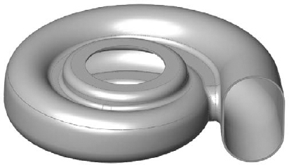
- Drag a window in the design tree to select the four fillet features. Then right-click and select Add to New Folder. Rename the new folder Fillet Folder.
- Click the Section View tool, and create a section view using the Front plane.
- Reorder the Fillet folder to after the Shell feature.
- At this point, you should notice that something does not look right. This is because creating the fillets after the Shell causes the outside fillets to break through some of the inside corners. The fillets should have failed, but have not, as shown in Figure 12.43.
- Choose Tools Options Performance, and select Verification on rebuild. Then click OK to exit the Performance menu and press Ctrl+Q. The fillets should now fail.
- Click Undo to return the feature order to the way it was.
- Save the part.

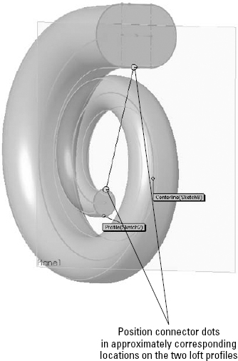
FIGURE 12.43 Fillets that should have failed

Summary
Working effectively with feature history, even in complex models, is a requirement for working with parts that others have created. When I get a part from someone else, the first thing that I usually do is look at the FeatureManager and roll it back if possible to get an idea of how the part was modeled. Looking at sketches, relations, feature order, symmetry, redundancy, sketch reuse, and so on are important steps in being able to repair or edit any part. Using modeling best practice techniques helps ensure that when edits have to be done, they are easy to accomplish, even if they are done by someone who did not build the part.
Evaluation techniques are really the heart of editing, as you should not make too many changes without a basic evaluation of the strengths and weaknesses of the current model. SolidWorks provides a wide array of evaluation tools. Time spent learning how to use the tools and interpret the results is time well spent.