
CHAPTER 13
Using Hole Wizard and Library Features
IN THIS CHAPTER
Exploring library features
Creating library features
Examining Dissection feature
Working with library features tutorial
The SolidWorks Hole Wizard is an automated tool that helps you place standard-sized holes in parts
Library features are user-defined, and you might use them in a similar way to how you use the Hole Wizard. They can be automated to some extent, and can make use of configurations. This chapter contains the information you need to decide how to implement and use the Hole Wizard and library features in your work.
Using the Hole Wizard
![]() The Hole Wizard enables you to place holes for many types of screws with normal, loose, or close fits. You can create Hole Wizard holes as assembly features in an assembly or as features in individual parts that are built in the context of an assembly using the Series Hole functionality. This tool is called a wizard because it guides you through the process step by step. A summary of the workflow of creating a Hole Wizard hole is as follows:
The Hole Wizard enables you to place holes for many types of screws with normal, loose, or close fits. You can create Hole Wizard holes as assembly features in an assembly or as features in individual parts that are built in the context of an assembly using the Series Hole functionality. This tool is called a wizard because it guides you through the process step by step. A summary of the workflow of creating a Hole Wizard hole is as follows:
- Pre-select the face to put the holes on, although this is not required. Versions after SolidWorks 2010 no longer require pre-selection to avoid 3D placement sketches; the Hole Wizard uses 2D sketches by default.
- Select the type of hole; for example, counterbored, countersunk, drilled hole, tapped hole, pipe tap, or legacy.
- Set the standard to be used, such as ANSI (American National Standards Institute) inch, ANSI metric, or ISO (International Organization for Standardization).
- Select the type of screw. For example, a counterbored hole can accommodate a socket head cap screw or a hex head screw, among others.
- Select the size of the screw. This is not the size of the hole. If you select a ¼-inch hole, the hole will not measure .250 inch; it will have the nominal diameter to fit a ¼-inch screw. You also have the option to select Show Custom Sizing to enter in custom dimensions for the hole directly, in case the hole is meant to accommodate something other than a standard-sized fastener.
- Select the fit of the screw into the hole, such as normal, loose, or close.
- Select the end condition of the hole.
- Select options for clearance and countersinks or edge breaks.
Alternatively, you can use or assign a favorite. A favorite is a hole with settings that you use frequently and want to save. I discuss these later in this chapter.
You can use Custom Sizing when you need a hole with nonstandard dimensions.
- Locate the center of the hole or holes. Switch to the Positions tab of the Hole Wizard PropertyManager to do this. You can place multiple holes in a single Hole Wizard feature, even on different faces and curved faces. I address the specifics of this step later in this chapter. Note that if you want to place holes on multiple faces, non-planar faces, or at different heights, you will need to do this with a 3D Sketch, on the Positions tab.
- Click OK to accept the type, size, and placement of the hole. Figure 13.1 shows the Hole Wizard PropertyManager interface.
FIGURE 13.1 The Hole Wizard PropertyManager interface

Defining the anatomy of a Hole Wizard hole
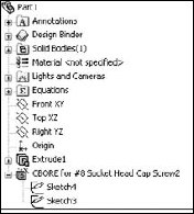
Hole Wizard holes are made of two sketches: a center placement sketch and a revolved cut profile. Figure 13.2 shows a simple part with an expanded Hole Wizard feature. Notice that the feature is named for the size and type of the hole.
FIGURE 13.2 A design tree containing a Hole Wizard hole
Using the placement sketch
The placement sketch is listed first under the Hole Wizard feature. It contains one or more sketch points marking the hole centers. It may also contain construction geometry with relations and dimensions to parametrically locate the hole centers. The placement sketch may be a 2D or a 3D sketch. A 3D sketch is more powerful, but also more complex and prone to difficulties. I discuss placement sketches in more detail in the next section.
Using the hole sketch
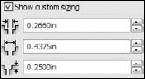
The revolve profile sketch is not on an identifiable sketch plane that you can reuse for other features. You can change the sketch dimensions outside of the wizard interface, and if you later use the wizard to edit it, then the changes appear in the Custom Sizing panel. Figure 13.3 shows the Custom Sizing panel with the changed counterbore diameter highlighted.
FIGURE 13.3 The Custom Sizing area of the Hole Specifications panel
If you change any of the options in the Options panel, the revolved sketch profile is altered to accommodate the change. For example, if you select the check box for a near side countersink, the sketch changes to add a line for the countersink; a separate chamfer feature is not added.
Using 2D versus 3D placement sketches
In SolidWorks 2010, SolidWorks changed the Hole Wizard so that it defaults to a 2D sketch. Pre-selection of a plane or planar face is still recommended because it eliminates a step later on, but it is no longer required in order to avoid being forced into a 3D placement sketch. Three-dimensional placement sketches are still available and still useful, but because they are so much more difficult to use and rarely truly needed, SolidWorks decided to change the default to a 2D sketch.
Three-dimensional placement sketches are needed for Hole Wizard holes if you have a set of similar holes that are placed on different levels or are always perpendicular to non-planar surfaces. If you need 3D placement sketches, they are still available, but they are no longer the default. To use a 3D placement sketch in a new Hole Wizard feature, just click the 3D Sketch button on the Positions tab. There is no way to change an existing 2D sketch to a 3D sketch. You would have to delete the feature and re-create it.
For most people who have learned SolidWorks software prior to the 2010 version, it may already be instinctive to pre-select a face before opening the Hole Wizard; this change will have no effect. It will have a positive effect on new users and those who frequently forget to pre-select.
Understanding the advantages and limitations of the 2D sketch
The main advantages of the 2D sketch method are the simplicity and completeness of the available tools. Everyone knows how to manage 2D sketches, sketch planes, dimensions, and construction geometry.
A limitation of the 2D sketch is that the holes that you create through this method are limited to a single planar face, and the holes will all be perpendicular to that face. Sometimes this creates a great limitation, while other times it does not matter.
Understanding the advantages and limitations of the 3D sketch
The obvious advantage of the 3D placement sketch is that it can put a set of holes on any set of solid faces, regardless of whether they are at different levels, are non-parallel, or are even non-planar. This function offers multiple holes, multiple faces, and multiple directions. In situations where that is what you need, nothing else will do.
A limitation of the 3D sketch is that it can be fairly cumbersome. Dimensions work very differently in 3D sketches compared to 2D sketches. For example, to create and place a hole in a specific position on a cylinder, you need to follow these steps:
- Begin with a circle with a diameter of 1 inch, drawn on the Top plane and extruded using the Mid-plane option 1 inch.
- Start the Hole Wizard without any pre-selection, either through the Features toolbar or by choosing Insert
 Features Hole Wizard.
 - Set the interface to use an ANSI inch, one-quarter-inch, and counterbored hole for a socket head cap screw. Use a Normal fit and Through All for the End Condition, with a .100-inch head clearance (in the Options panel) and no custom sizing changes. These settings are shown in Figure 13.4.
- Click the Positions tab, which is located at the top of the PropertyManager window. The interface asks you to select a face where you would like to put the holes or to select the 3D sketch option. In this case, click the 3D Sketch button.
Note
Be careful with clicking when the Point tool is turned on. For example, if you click in a blank space, the Point tool places a point off the part. SolidWorks will try to use the point later to create a hole in empty space, which usually causes an error.
FIGURE 13.4 The Hole Wizard settings for the socket head cap screw
- Click the cylindrical surface of the part. The surface appears orange when you move the cursor over it to indicate that an OnSurface sketch relation will be created between the sketch point and the cylindrical surface.
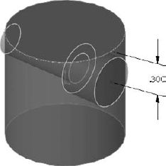
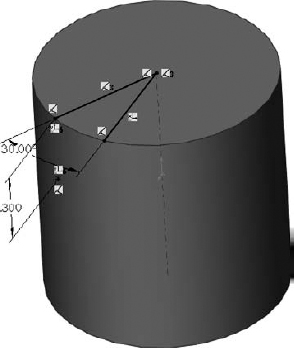
- The hole should be positioned from one end of the cylinder. Using the SmartDimension tool, click one flat end face of the cylinder and the sketch point. Place the dimension and give it a value of .300 inches, as shown in Figure 13.5.
Locating the point angularly around the cylinder is more difficult. You can use several methods to do this, but this example shows one using construction sketch geometry.
FIGURE 13.5 Dimensioning the 3D Placement sketch point
To force a 3D dimension to have a certain orientation, dimension from a plane or planar face rather than from an edge, vertex, or sketch entity. A dimension from a plane is always measured in a direction perpendicular to the plane, but a dimension from a line or point is always measured by the shortest distance between the entities. Two-dimensional sketches can force dimensions to be horizontal or vertical, but 3D sketches cannot.
- With the Line tool activated while still in the 3D sketch, Ctrl+click the flat end face that the previous dimension referenced. This moves the red “space handle” origin to the selected face and constrains any new sketch entities to that face. You are still in the 3D sketch but are constrained to the selected plane and still must play by all the 3D sketch rules. The elements of 3D sketches are described in detail in Chapter 6.
- Select the Temporary Axes view by choosing View Temporary Axes.
- Place the cursor near the center of the activated end face; a small, black circle appears, indicating that the end point of the line will pick up a coincident relation to the temporary axis. Draw the line so that it picks up an AlongX sketch relation. The cursor shows the relations about to be applied, just like in a 2D sketch.
- Draw a second line again from the center, but this time do not pick up any automatic relations. This line should also be on the flat end face.
Note
Although you can set these lines to display as construction lines if you like, this is not required for the feature to work; the lines also work as regular solid lines.
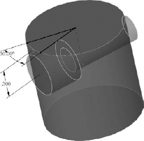
- Put an angle dimension between the lines and change the angle to 30 degrees. To be thorough (which is always recommended in 3D sketches, which have a tendency to handle underconstrained sketch geometry unpredictably), constrain the ends of the lines to the circular edge of the cylinder. At this point, the part looks like Figure 13.6.
FIGURE 13.6 The example part at the end of Step 11
- Create an AlongY sketch relation between the points indicated in Figure 13.7. The hole centerpoint on the cylindrical face is one of the points, as well as the endpoint of the angled line. Change the angle dimension to ensure that it is controlling the sketch point as expected. Click the green check in the upper-right corner of the graphics window to accept the result and exit the command.

FIGURE 13.7 Control the placement of the 3D sketch point around the cylinder.
On the DVD
You can find the finished part from this example on the DVD with the filename Chapter 13 3D Hole Placement.sldprt.
Cross-Reference
Chapters 6 and 8 contain more information on general 3D sketch tools and techniques.
Making and using favorites
Hole Wizard Favorites store types of holes that you use frequently so that you can simply recall a favorite, rather than manually making all the changes every time you use the same hole. Favorites are saved to a database named Default.mdb as you create them, and are immediately available from all other part documents connected to that database. You can also save favorites to a special file type with the extension *.sldhwfvt. Other users can then load these files and add your favorites to their Default.mdb databases. This is a convenient way to create company standards for hole features.
Shared Toolbox installations share a SWBrowser.mdb between several users, making Hole Wizard Favorites available to everyone. I cover how to set up shared Toolbox installations later in this chapter.
Creating a Hole Wizard Favorite
To create a Hole Wizard Favorite, set up a Hole Wizard hole as you normally would, and then use the Add Favorite button to add it to the Favorites database. The Hole Wizard Favorite panel contains five buttons:
 Apply Defaults/No Favorites. Removes favorite settings from the current interface, setting all values back to their defaults.
 Add or Update Favorites. Either adds a new favorite to the database or changes the name or other settings for an existing favorite.
 Delete Favorite. Removes a favorite from the database.
 Save Favorite. Saves a favorite to an external file with the extension *.sldhwfvt, which can be loaded by other users and added to their databases.
 Load Favorite. Loads a saved favorite file.
Storing custom holes
You can use Hole Wizard Favorites to store custom holes. Create the hole with its custom sizes, and then add the favorite and give it a recognizable name. The custom hole will now be available to anyone who connects to the same database file.
Administering Hole Wizard Favorites
The database file is typically found in the Data subdirectory of the SolidWorks installation directory, but an option in Tools ![]() Options
Options ![]() File Locations
File Locations ![]() Hole Wizard Favorites Database theoretically enables you to move the file to somewhere else.
Hole Wizard Favorites Database theoretically enables you to move the file to somewhere else.
Further, the *.sldhwfvt files do not have an entry in the File Locations list, but seem to always default to the langenglish subdirectory of the SolidWorks installation directory. Neither this location nor the Data directory makes sharing among multiple users very convenient, but both file types can be copied to other installations.
Best Practice
It is a best practice to create a folder for library type files that you want to save and use with a future version of SolidWorks. You can specify the locations for these files by choosing Tools ![]() Options
Options ![]() File Locations. I recommend a location such as D:Library. This moves the file off of the same drive as the operating system, in case you need to reformat, and it keeps it out of the Program Files area to prevent it from being lost or overwritten when SolidWorks is installed, uninstalled, upgraded, or changed in other ways
File Locations. I recommend a location such as D:Library. This moves the file off of the same drive as the operating system, in case you need to reformat, and it keeps it out of the Program Files area to prevent it from being lost or overwritten when SolidWorks is installed, uninstalled, upgraded, or changed in other ways
Confronting favorites quirks
Hole Wizard Favorites seem to have a couple of quirks that are possibly “suboptimal,” as they say. First, you can only see the favorites for a specific type of hole when that type of hole is activated in the interface. For example, if you have a number of favorites for countersunk holes, but you currently have the counterbored hole icon activated, you will not be able to see the countersunk favorites until you switch to the countersunk icon.
If you have a lot of favorites, this may be beneficial, but if you have only a few favorites, or you do not use favorites frequently, it may be confusing and can create some unnecessary steps to find all your favorites.
A second quirk occurs when you allow SolidWorks to name the favorites and you have fractional values such as ¼ — which happens now and then in hole sizes — and then try to save the favorites. Each favorite is saved as a separate file, using the name that was automatically assigned to it by SolidWorks as the filename. Unfortunately, the character “/” is not allowed in a filename, so it fails.
Using the Hole Series
![]() The Hole Series enables you to make a series of in-context hole features in individual parts that are connected by a Hole Series assembly-level feature. It is intended for a stack of parts where, for example, the top part has a counterbored hole, the middle part has a clearance through hole, and the final part has a blind threaded hole.
The Hole Series enables you to make a series of in-context hole features in individual parts that are connected by a Hole Series assembly-level feature. It is intended for a stack of parts where, for example, the top part has a counterbored hole, the middle part has a clearance through hole, and the final part has a blind threaded hole.
The Hole Series functionality is covered in more detail in the SolidWorks 2011 Assemblies Bible (Wiley, 2011), as it is only used when you have an assembly.
Using Library Features
Library features are features that you create once and reuse many times. They are intended to be parametrically flexible to fit into many types of geometry, but they can also be of a fixed size and shape. You will use all the information that you have learned in previous chapters about designing for change, and design intent, as well as learn how to create, use, and store library features.
Library features reside in the Design Library, which is located in the Task Pane to the right of the graphics window.
Tip
You can detach the Task Pane from its docking location and move it wherever you want, leave it undocked, or move it to a second monitor.
You can use library features for snap ring grooves, custom holes, mounting bosses for plastics, mounting hole patterns, electrical connector holes, and much more.
One very useful aspect of library features is that they can be driven by configurations and design tables. Once the feature is in the part, the configurations are still available, and so you can change the config of an applied library feature at any time.
You can also link a library feature to an external file. This enables you to change a feature or a set of features in several parts at once if they are all externally linked to the file.
Getting started with library features
Library features are simple to use and only slightly less simple to set up. For that reason I discuss using them first, so that you know what kind of behavior you are trying to create when you go to make your own features. As a result, setting them up should make a little more sense.
To use a library feature, you just drag-and-drop it from the Design Library onto the appropriate geometry. You are then prompted to select references in the new part that match the base geometry that the library feature is attached to. You can be fairly creative with references, but one of the goals when creating the feature is to make it work with as few references as possible, in order to make it easy, fast, and reliable to use.
SolidWorks software installs with several sample library features in the Design Library. The following demonstration uses some of these standard library features. Later, you can add library features from the DVD to your Design Library.
Applying the library feature interface
Library features work best if they go from a certain type of base geometry to a similar type of base geometry; for example, from rectangular to rectangular or from circular to circular. This is because the relations or dimensions that link the feature to the rest of the part tend to be dimensions from straight edges or concentric sketch relations. Of course, there are other ways of applying library features, but these are the most prevalent. Library features can be applied unconstrained and then constrained or moved later, but the process is cleanest when it all just falls together correctly the first time.
Using the Task Pane
You do not have to save the part or do anything special before applying a library feature. All you need to do is find the Task Pane. The Task Pane is the window that flies out from the right when you open SolidWorks. You may have turned it off and forgotten about it, in which case you can turn it back on by choosing View ![]() Task Pane from the menu.
Task Pane from the menu.
The Task Pane automatically closes when you click outside of it unless you pin it open using the push-pin icon in the upper-right corner of the window. When you do this, any toolbars that appeared on the right side of the Task Pane control tabs are moved out and positioned between the graphics window and the Task Pane, which now remains open by default.
You can also detach the Task Pane by dragging the bar at the top of the pane. Figure 13.8 shows the Task Pane docked to the right side of the SolidWorks window.
Tip
If you are using dual monitors, you can drag the detached Task Pane onto the second monitor, which enables you to use the Task Pane and at the same time gives you more room in the graphics area. You must do this for each session; the Task Pane does not remember positions on a second monitor.
Using Design Library
![]() The Design Library tab displays an image of a stack of books. It is the overall library area for all sorts of elements in SolidWorks, which I discuss later in this chapter. The only part of the Design Library of concern right now is the Features folder. If you expand this folder, you can see that it is populated with some sample features.
The Design Library tab displays an image of a stack of books. It is the overall library area for all sorts of elements in SolidWorks, which I discuss later in this chapter. The only part of the Design Library of concern right now is the Features folder. If you expand this folder, you can see that it is populated with some sample features.
Open a new part and create a cylinder using any method you want (for example, extrude, revolve). Make the diameter 3 inches and the length a little more than 1 inch.
FIGURE 13.8 The Task Pane docked to right side of the SolidWorks window
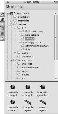
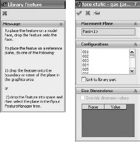
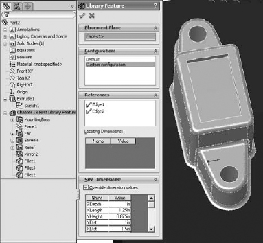
In the Inch features folder, click the folder called o-ring grooves. The first feature in the list is called face static – gas. Drag-and-drop this feature onto the end flat face of the cylinder. As shown in the image to the left in Figure 13.9, the PropertyManager displays a yellow information panel explaining the process.
The next step is to select the configuration, as shown in the image to the right in Figure 13.9. Not all library features have multiple size configurations, but these do. The configs in this case are driven by design tables. Select configuration 330.
FIGURE 13.9 Placing the feature and selecting the configuration
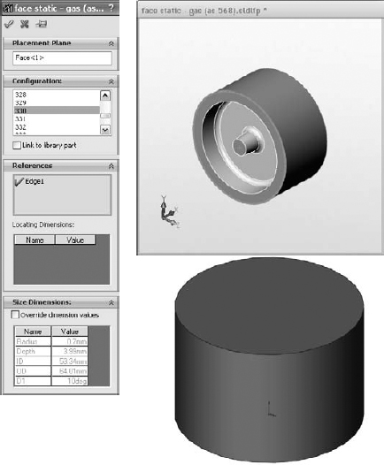
When you select the configuration, the interface changes. In this case, only a sketch relation locates the feature; it is not located by dimensions. Notice that in the References panel shown in Figure 13.10, there is an Edge entry with a question mark, which becomes a check mark after you select the edge. This means that the library feature needs a circular edge to locate it. Notice that a small window appears, displaying the library feature. You may not be able to distinguish it in Figure 13.10, but the circular edge around the face that the library feature is on is highlighted in green. This indicates that you need to select an edge that has the same relation to the library feature as the highlighted edge. Pick the circular edge of the part on the end of the cylinder where you want to place the library feature.
FIGURE 13.10 Locating the library feature
Next, use a rectangular part where the library feature is located by using dimensions rather than sketch relations. Create a rectangle 1.5 inches by 2 inches and extrude it to about 2 inches in depth.
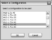
In the Design Library, browse to features, then inch, and then the fluid power ports folder and drag the sae j1926-1 feature onto the end of the extruded rectangle. Select the 38-24 size from the configurations list. A window appears, prompting you for reference selections, as shown in Figure 13.11.
FIGURE 13.11 Placing a library feature with dimensions

Tip
It is often helpful to orient the part that is receiving the library feature in the same way as the part shown in the preview window. This helps you to visualize which edges to select.
After the locating edges have been identified, the Locating Dimensions box becomes active and you can change the values of the dimensions to locate the feature. Further, in the Size Dimensions pane at the bottom of the PropertyManager, selecting the Override dimension values option enables you to change dimensions of the feature itself.
When you use a library feature with a design table, the design table is not brought into the part with the library feature. If the part already had a design table, this would cause multiple tables, which is not currently possible in SolidWorks. The configurations in the design table are brought forward, however.
If you override the feature dimensions using the Override Dimension Values option in the Size Dimensions panel of the Library Feature PropertyManager when feature configurations already exist, then a new configuration called Custom Configuration is created in the list of feature configurations. It appears that multiple custom configurations are not allowed, and so if you have to make changes, then you must ensure that they are right before you use the library feature in a part.
Exploring other Design Library functions
The Design Library has other functions besides library features. For example, you can use it as a repository for other items that you use frequently.
Storing annotations
You can store commonly used annotations in the Design Library. If you look at the Annotations folder with the default sample annotations, you see a combination of symbols and blocks. You can use symbols and notes in 3D models, but you can only use blocks in sketches or 2D drawings. Keep in mind that not all annotation types can be used in all places.
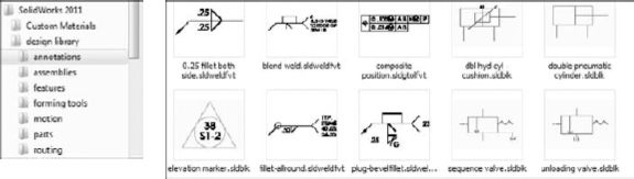
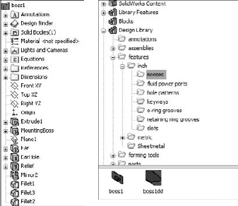
Annotations can be stored in the library as favorites or blocks. Many file extensions are used for different types of favorites, but they typically begin with *.sld and end with fvt, as in *.sldweldfvt. Figure 13.12 shows the default location of the Design Library and the Thumbnail view of the favorites and blocks in the Annotations folder.
FIGURE 13.12 The Annotations folder in Windows Explorer
Note
The screen capture with the thumbnails displayed was taken in Windows XP. The capture of the folders was taken in Windows 7. I am not able to get thumbnail images of the favorites to display in Windows 7 with SolidWorks 2011 sp0.0 installed, but thumbnails for the blocks appear to work okay. This issue is not resolved as of this writing.
Location of the Design Library folder
If you frequently work with different types of annotations, then you should organize the library into subfolders to separate symbols, annotations, and blocks, and move these folders to a different location. By default, the Design Library folders are found at C:ProgramDataSolidWorksSolidWorks 2010design library. You should store them in another location, not in the SolidWorks installation directory, but in an area that you have selected to maintain SolidWorks data between releases. For example, I have a folder at D:Library that contains folders for macros, templates, library features, library parts, favorites, and so on. You can easily back up or copy these files from one computer to another, although you must quit SolidWorks before making these changes. Keeping the data off the operating system drive is also a good idea because if you ever have to reinstall the OS, you will not lose your SolidWorks library data.
After moving the library, you have to point SolidWorks to the new location. To do this, choose Tools ![]() Options
Options ![]() File Locations
File Locations ![]() Design Library. Delete the old location and browse to the new location. You should move other items in this list and redirect any items that you use, such as the templates and any other items you use frequently. Once you have specified the settings, they should be retained when you install service pack upgrades or future versions.
Design Library. Delete the old location and browse to the new location. You should move other items in this list and redirect any items that you use, such as the templates and any other items you use frequently. Once you have specified the settings, they should be retained when you install service pack upgrades or future versions.
Storing library parts
The Design Library can also store commonly used library parts. One of the advantages of using the library for parts is that on placement into the assembly, if configurations are available in a part, then a window pops up, enabling you to select which configuration to place into the assembly.
Note
In many cases, using the Design Library for library parts is considered an acceptable replacement for the automated function of Toolbox. If you use Toolbox to make the parts and populate them with configurations, and then save the parts out of Toolbox and into the Design Library, many options, including naming conventions, and a more flexible use of custom properties that are not available through Toolbox become available.
Figure 13.13 shows the configuration selection window. Note that the configurations are alphabetically listed, and you can type in the box to go to the configuration that you want.
FIGURE 13.13 Inserting library parts with configurations
Parts inserted from the library parts folder can also take advantage of the Mate References functionality in the same way as Toolbox, by allowing parts to snap into place.
Using sheet metal forming tools
I only mention sheet metal forming tools here as a part of the library. They work much like other library features, but they do so within the specialized functions of sheet metal parts in SolidWorks. I discuss sheet metal forming tools in Chapter 21. Forming tools folders have special properties. If you want to use the parts in a folder as forming tools, you must right-click the folder in the Design Library and choose Forming Tool Folder. The only other library type that needs special folders is library assemblies.
Using assemblies
You can use library assemblies in SolidWorks in the same ways that you use library parts because they are inserted into the top-level assembly as a subassembly. For subassemblies that require motion, such as universal joint subassemblies, you can set the subassembly to solve as flexible or simply dissolve the subassembly into the upper-level assembly, through a RMB option.
Tip
When saving assemblies to the library, it is recommended that you put the parts in a separate folder to segregate the parts of different assemblies.
Using routing
Routing is a separately purchased add-in that is included with SolidWorks Office Premium. It includes piping, tubing (rigid and flexible), and wiring. Routing makes extensive use of libraries and automation but is not part of the scope of this book. The documentation on routing at this time is rather sparse, but SolidWorks offers a reseller training class, and at this time, it's your best bet for information on this add-in.
Using Smart Components
Smart Components are components that resize by automatically selecting configurations, depending on the size of the geometry onto which they are being dropped. They do this from a design table–like interface that you set up to enable it to automatically select part configurations based on mating part sizes. For example, a clamp with many sizes driven by configurations would select the correct config when dropped onto different sizes of cylinders.
Creating Library Features
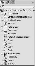
When you save library features to the library, they use the file extension *.sldlfp (library feature part). They must contain some base geometry, which simulates the part onto which the feature will be dropped. The base geometry is not transferred to the new part; only features that are marked with the “L” in the FeatureManager (for Library) are transferred to the new part. Figure 13.14 shows the FeatureManager of a library feature part.
FIGURE 13.14 The FeatureManager of a library feature part
Creating a library feature
When creating a library feature, the first problem that you need to solve is how the feature will be located on a new part. Does it need to be placed on cylindrical parts, rectangular parts, other types of shapes, or does this matter at all? Will the feature be located by using dimensions or sketch relations, or will it just be placed underdefined and later fully defined manually rather than automatically?
You may have noticed in one of the earlier examples that the sample fluid power ports had two versions of the same feature. One version is intended for the feature to be placed on the flat end of a cylinder, and the other version is intended for the feature to be placed on a rectangular face.
Understanding library limitations
Library features can contain multiple features of different types. They may add and remove material, even within a single library feature. However, a few limitations exist. For example, they require a base feature, and multi-body features and external references are not allowed, nor are surfaces, sheet metal, weldments, or molds-related features. In addition, you cannot add a scale feature (a feature that affects the entire body) to the library, nor can you apply library features to an assembly.
Creating a new library feature
To start a new feature, the first decision that you need to make is what shape to make the base. Is the feature a type that is usually going to go onto a single shape or multiple shapes? Regardless of your decision, you or whoever ends up using the feature will have the flexibility to change, or simply not use, the relations when you place the feature.
For this example, I use a rectangular base. The library feature that I want to create consists of two boss extrudes, a cut extrude, and several fillets. Here is how it works.
First, you need to create a rectangular extrusion. The size should be bigger than the feature that goes on it and representative of the face of the end part onto which this feature will typically be placed.
Next, in beginning to create the features that you want to reuse, it is very important that you pay attention to any references outside of the sketch; these include absolutely anything outside the active sketch, such as the sketch plane, references to edges, the Origin, other planes, other sketches, and axes. Although these references are allowed, each reference to anything that is not already part of the library feature must be reconnected when you place the feature on a new part. The ideal situation is obviously a single drag-and-drop, but generally speaking, at least one other step is usually needed. The initial drag-and-drop determines the face for the feature to start from, and from there, you usually need to locate features, either by using relations or dimensions. A concentric relation locates the feature in a single reference selection of a circular edge (although it may also need to be rotated), and dimensions typically require one dimension in the X dimension and another one in the Y dimension.
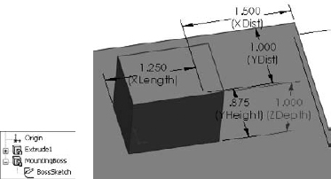
Figure 13.15 shows the base feature and the first feature of the library feature. The only relations between the sketch of the library feature and the base feature are the sketch plane and the two dimensions.
Note
Notice that names have been assigned to all the dimensions, sketches, and features. This is because the dimension names all display in the interface. If you look back to Figure 13.4, in the Size Dimensions pane, dimension names make it easy to know which dimension to change, whereas the D1 dimension leaves you guessing as to what it applies.
FIGURE 13.15 Creating a library feature
You should ensure that subsequent features after the first one reference only the first feature of the library feature (which is the second feature in the part). This is not a mandatory requirement, but a helpful guideline. You can make additional references, but they should be limited to the same items that were already referenced if possible. Users who model carelessly or do not pay attention to what they are doing typically have trouble making library features that function and are easy to use. Successful modeling of library features is like planning a strategy in a game of chess.
Now you can add the second extruded feature, being careful to reference only geometry that is going to move with the library feature. Figure 13.16 shows the newly added feature. If you would like to follow along as I detail how this feature is built, you can open the part from the DVD under the filename Chapter 13 First Library Feature.sldlfp.
FIGURE 13.16 Adding the next feature to the library feature

Notice that a plane has been added. The plane is made to only reference geometry that is internal to the library feature; it is perpendicular to an edge at the midpoint, which simultaneously locates and orients the plane correctly to enable it to be used to mirror the Ear feature.
Also, notice that the EarSketch uses the same face reference from the base feature. This will appear in the Reference list as a single reference.
Saving the library feature
You can use two methods to save a library feature. You can either drag-and-drop it into a Design Library folder or use the Save As method. Because Save As is a little more common, I describe it first.
The first step in saving the library feature is to select all the features in the FeatureManager that are intended to be a part of the library feature. Collapse the features first so that the sketches belonging to features are not selected. If the sketches are selected, you may get a warning message saying that no selected features can be used in the library feature. Do not worry; the sketches still will be included.
Tip
Remember that you can Ctrl+select individual features, Shift+select a range, or click-and-drag a selection box in the FeatureManager to select multiple features. Also keep in mind that if you do not select a feature (other than the base feature), then it will not be placed into the part when you insert the library feature. If there were any relations to the omitted feature, they may display as errors or warnings when you place the feature.
With the features selected, click File, click Save As, and under Files of Type drop-down list, select the *.sldlfp file type. Browse to the Design Library folder and save the part. Figure 13.17 shows the FeatureManager of the finished library feature.
FIGURE 13.17 The finished library feature part
Changing the display of the library feature thumbnail
During the Save As process, a new folder was added to the Design Library named Bosses, as shown in Figure 13.17. Notice the new icon for the library feature in the lower window. You may notice that some of the default library features saved in the Design Library have a bluish background. This occurs because of the SolidWorks viewport background color, which you can set by choosing Tools ![]() Options
Options ![]() Colors. Even if you never see that color because you are using a gradient background or a scene, SolidWorks still uses the color specified by that setting as the background when saving thumbnails and previews. I always set this color to white for this reason, so that document backgrounds in previews do not have the blue color.
Colors. Even if you never see that color because you are using a gradient background or a scene, SolidWorks still uses the color specified by that setting as the background when saving thumbnails and previews. I always set this color to white for this reason, so that document backgrounds in previews do not have the blue color.
You may want to orient and zoom the library feature before saving it so that it displays clearly in the panel. One of the techniques that I like to use is to make the base feature a different color than the library feature itself; this helps you to more easily determine what is the geometry that will be transferred and what is just dummy material.
Tip
Figure 13.18 shows various settings for displaying the icons in the Design Library. Which one you select will depend on your screen resolution, the number of icons that you want to display, and the quality of the preview images.
FIGURE 13.18 Display modes for the Design Library

The real test for a library feature comes when you actually use it. This feature is re-created perfectly on the new part, but I have noticed one problem. When the feature was placed, it was 90 degrees away from the orientation that I wanted it to be in. It seems that the only way to make the feature rotatable is to create it with parallel and perpendicular relations rather than horizontal and vertical ones, so that one of the references can act as a rotation reference. Figure 13.19 shows the completed library feature placed on a part.
FIGURE 13.19 The completed library feature placed on a part
Once you place a library feature on a part, it can be edited unless you select the Link to library part option in the Configuration pane, in which case the feature is driven externally from the *.sldlfp file. The Link to library part option is only available when the feature is first placed; it is not available when you edit an existing library feature in a part.
One of the available RMB menu options is to dissolve the library feature so that all the constituent features become regular features in the main part. Doing this on a configured library feature will destroy the configurations.
Creating a library feature from an existing part
When creating a library feature from an existing part, you use essentially the same process, but it is somewhat more difficult to achieve the correct results. It is best to remove all the features that do not either form the base feature or go into the library feature itself. This can cause many broken references. Most parts are not modeled with creating a library feature in mind, and creating library features with effective references, as I mentioned earlier, is like a chess match and requires some forethought. It may be better to use a different technique, such as creating a new part with only the base feature. You can then Ctrl+drag the desired features from the existing part to the new part, set up the rest of the library feature, and save it with a *.sldlfp extension.
You can also create a library feature by dragging and dropping, although there are some limitations with this technique that seem to override the convenience. However, there is a workaround for the biggest limitation. If you select faces from features and drag them into the lower Design Library window, an Add to Library PropertyManager interface appears to enable you to start creating a library feature. The Add to Library PropertyManager interface is shown in Figure 13.20. You must select the features from the flyout FeatureManager. This is the source of one of the limitations. In the example, the plane cannot be selected by this method. The workaround for this is to complete the feature without the plane, right-click the icon in the Design Library window, and then select Open. With the library feature open in its own window, right-click the plane feature and select Add to Library; that individual feature is then added.
FIGURE 13.20 The Add to Library PropertyManager interface

Adding folders to the library
You can add folders to the library in two ways, either by right-clicking in the Design Library window and selecting New Folder or by using the Windows Explorer interface. Another RMB menu option is Add Existing Folder, which enables you to add a folder from another location to the library. The folder is not moved or copied, but a shortcut is added to the Design Library and the contents appear in the lower pane.
Tip
After a library feature has been edited, or folders or documents have been added to the library using Windows Explorer, you can press F5 in either the lower or the upper window to update the display for that window or use the Refresh icon located at the top of the Task Pane.
Locating and Internal dimensions
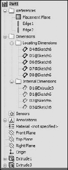
When you create a library feature, SolidWorks adds two folders to the FeatureManager: the References folder and the Dimensions folder. In turn, the Dimensions folder has two more folders: Locating Dimensions and Internal Dimensions. All these folders are shown in Figure 13.21.
The References folder shows the entities you used to reference the library feature. These are the features you are prompted to select upon placing the library feature in a new part. No additional work on your part is required with this folder.
The Dimensions folder lists all the dimensions in the library feature. Some of these dimensions are used to locate the feature to the dummy block and some are meant to size the feature itself. When you make a library feature, it is recommended that you separate the locating features from internal features by dragging the dimensions into the separate folders. The Locating Dimensions can be changed while placing the library feature, but the Internal Dimensions cannot be accessed. You might want to limit user access to some dimensions if you have standard tooling for the library feature that you are creating.
FIGURE 13.21 References, Locating Dimensions, and Internal Dimensions in a library feature
Understanding Dissection
Dissection is a process that SolidWorks goes through by which it examines all the parts on your computer and makes Design Clipart of the sketches and features. People who might get some use from this function are those who have not modeled a lot of parts and will tend to reuse the same features over and over again. The types of data it will try to recycle for you are extrudes and cuts, sketches, blocks, and tables from drawings.
The first interaction most people have with this function is learning how to turn it off. If you notice your computer starting to run small SolidWorks windows in the background starting at about 11 pm daily, you may have Dissection turned on. To select or deselect Dissection, choose Tools ![]() Options
Options ![]() Search. Dissection is connected to SolidWorks Search, another function many users prefer to deselect.
Search. Dissection is connected to SolidWorks Search, another function many users prefer to deselect.
Tutorial: Working with Library Features
This tutorial guides you through customizing a Hole Wizard hole to use as a specialty library feature, then storing it in the library, editing it, and placing it in a part. Follow these steps:
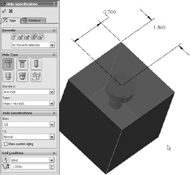
- Open a new part, and create a rectangular base feature, about 3 inches high by 3 inches wide and 3 inches deep.
- Pre-select a flat face and start the Hole Wizard.
- Create a counterbored hole for a Heavy Hex Bolt, ½-inch, Normal Fit, Blind, 1.2 inches deep. Locate the hole with dimensions from two perpendicular edges, as shown in Figure 13.22. Click the green check mark icon twice to accept the hole settings.
- Turn on the setting at View Dimension Names.
- Double-click the counterbored hole feature in the FeatureManager to show the dimensions. Make sure Instant3D is unselected for the next step.
- Click one of the dimensions that you created to locate the center of the hole and rename the dimension in the Dimension PropertyManager (Primary Value panel) using names that will have meaning when you place the dimension, such as XDir, or YDir. Do this for both dimensions.
- Edit the second sketch of the hole. Figure 13.23 shows what the sketch should look like before and after the edit.
Caution
Do not delete any of the named dimensions in a normal or revised Hole Wizard hole. SolidWorks has a checking mechanism that looks for these names and will display an error if any of the named dimensions is not there. If there is no use for the dimension, it still has to be there, although it does not need to be used for its original use. You could rename another dimension with the name or simply dimension the length of the centerline or an otherwise unused construction line. It does not matter about the function of the dimension, as long as there is a dimension with that name in the sketch.
Tip
You should also name any new dimensions that you may want to change. These dimensions will have more meaning when you are placing the feature if they have names. Be aware that the two angled lines are parallel and equal length. This will enable you to get a fully defined sketch.
FIGURE 13.23 Reconfiguring the hole

Remember that to get the diameter dimensions shown in Figure 13.15 (instead of radius dimensions), you must use the dimension tool to select the centerline (construction line) and the line or endpoint on one side, and then move the cursor to the other side of the centerline to place the dimension (the order of selection does not matter). When the cursor crosses the centerline, the dimension will display as a diameter instead of a radius.
- When you are done editing the sketch and renaming dimensions, exit the sketch.
- Click the CBORE feature twice, or click it once and press F2 to rename it as SpecialHole.
- Pre-select the same flat face that the first hole feature was placed on and then start the Hole Wizard again.
- Place a #8-32 tapped hole, accept the default depth, and specify a center-to-center distance of .75 inches between it and the SpecialHole in the Horizontal or Vertical direction. Rename the radial dimension as MountRad.
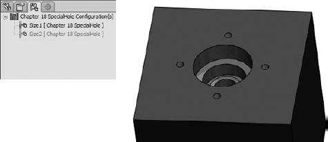
- Using a cylindrical face of the SpecialHole, make a circular pattern of the new tapped hole, creating a total of four instances of the tapped hole. Make the SpecialHole Feature red and the tapped hole and pattern yellow.
- Split the FeatureManager window into two by using the splitter bar at the top. Change the lower panel to the ConfigurationManager.
- Rename the Default configuration Size1.
- Create a new configuration called Size2. Double-click the SpecialHole feature and change the dimension named C'Bore Dia to 1.5 inches. Be sure to change to This Configuration Only using the drop-down menu.
- Make a dimension change for the MountRad dimension to 1 inch. The results to this point are shown in Figure 13.24.
FIGURE 13.24 The results after Step 16
- Auto-create a design table by choosing Insert Design Table and then selecting the Auto-Create option. Edit the design table to look like Figure 13.25. Hide or delete extra columns that don't match the data shown.
FIGURE 13.25 The design table for the SpecialHole feature
Tip
Remember that to fill the first two columns up to Size5, you can make the two-by-two selection of the Size1 and Size2 entries in the first two columns and pull down the handle in the lower-right corner of the selection box until the appropriate boxes are filled.
- Manually fill in the C'Bore Dia values, but in cell D3, type the equation =C3/2+.25. Then use the same Fill technique to populate cells D3 to D7. Click outside of the Design Table to close it.
- Test the configurations to make sure that they all work.
- In the Design Library, browse to a folder where you would like to put this library feature. (Make sure that it is not used by assemblies or sheet metal forming tools.) Click a face created by the SpecialHole feature and drag the feature into the lower pane of the Design Library. The Add to Library PropertyManager should appear on the left.
- Although you selected a feature and dragged it into the library, the Items to Add field appears blank. Select the SpecialHole, tapped hole, and circular pattern features using Ctrl+select for multiple selections, either through the detachable PropertyManager, the split FeatureManager, or the flyout FeatureManager. Selecting the features from the graphics window does not work.
- Position and zoom the view of the part so that when it is saved, you see a good preview of the library feature. Also, if you have not changed your background color from blue to white, this would be a good time to do so.
- In the Save To pane, make sure that you select the correct folder, then fill in a filename and click OK. Figure 13.26 shows the completed PropertyManager interface for this function.
Tip
You may notice that there are two library entries in the window. This is because an additional path has been added in Tools
Options File Locations Design Library. - If the new library feature does not appear in the Design Library, then click in the Design Library and press F5. If you do not like the way that it displays, then right-click in a blank space inside the lower library window and select one of the other three options.
- To edit the preview image of the feature, right-click the feature in the Design Library window, select Open, reposition or zoom the view, and save it. Click in the Design Library and press F5 again.
Tip
It is recommended that when placing a library feature, you should close the original library feature window. The workflow proceeds much more smoothly if the part is closed before you use it.
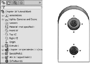
- Open the part from the DVD called Chapter 13 Tutorial Blank.sldprt. If you would like to examine the version of the SpecialHole part that I created, it is saved as Chapter 13 – SpecialHole.sldlfp. Notice that this is a library feature part file, not a regular SolidWorks part file.
- Drag the SpecialHole library feature from the Design Library onto the face of the blank part. Place the feature near the squared-off end. Select a configuration from the list in the PropertyManager.
Although there is no prompt, when the Library Feature interface hesitates and there are configurations in the library feature, it is waiting for you to select a configuration. A prompt actually does exist, but it appears in the lower-left corner of the screen on the status bar in a tiny font and most users probably do not notice it.
- Try to orient the part in the same way that it appears in the preview window, as shown in Figure 13.27.
FIGURE 13.27 Orienting the part and selecting references
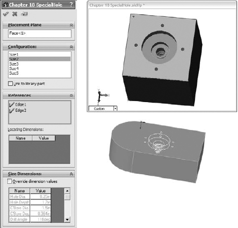
- Select edges on the Blank part that correspond to the preview window. Click OK to accept the placement of the feature.
- Double-click the SpecialHole feature and change the X and Y placement dimensions to place it 1 inch from the edges in both directions.
Note
You may remember from Chapter 11 that library feature configurations cannot be controlled by part configurations. In order to show different library feature configurations in different part configurations, you need to suppress one library feature and insert another. This is the best available workaround. It may be time to visit that enhancement request site again.
- Place another library feature onto the blank part. Select a configuration, and click the green check mark icon without selecting edges for the references.
- Notice that the feature in the FeatureManager appears with an exclamation mark. If you investigate the cause of this, then you can see that the two dimensions that should be attached to edges are dangling because you did not select the references while placing the library feature. This was done on purpose to show a different technique.
- Expand the library feature and the SpecialHole feature, and edit the first sketch in the Special Hole. This is the placement sketch. Delete the two dimensions that appear in dangling colors.
- Add a concentric sketch relation between the placement point and the arc edge of the Blank part. Exit the sketch. The error message should now be gone and the hole should now be placed in the center of the arc.
- Right-click the second library feature and select Dissolve Library Feature. Figure 13.28 shows the finished part and FeatureManager. Good job!
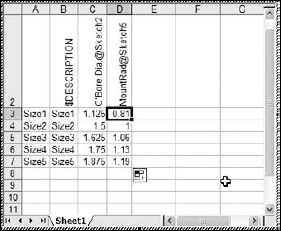
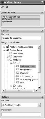
FIGURE 13.28 The finished part
Note
When you dissolve a library feature, you lose any access to any configurations. Some users insist on dissolving every library feature so that they can see regular features in the FeatureManager. This technique may also be useful if you would like to reorder some of the individual features within the library feature.
Summary
The Hole Wizard can make holes based on 2D or 3D sketches. The type of hole that you create is up to you. Two-dimensional sketches are far easier to use than 3D sketches.
Library features are very useful in automating frequent design tasks. They are easy to create, store, apply, and automate. Setting up the features for the most flexibility often takes careful planning and attention to the detail of the references that you use. The more data you reuse, the more time you will save by automating and centralizing your libraries.